Abstract
This paper proposes a low-cost on-chip Hardware-in-the-Loop (HIL) platform for teaching and fast prototyping of dynamic systems. A dual-core digital signal controller (DSC)-based solution is proposed for the HIL system. CPU core A, as the simulation engine, is dedicated to circuit and system simulation. The actuation and control logic are implemented in CPU core B, which is working as the control engine. Inter-processor communication is used to interchange variables between the CPUs. The digital-to-analog converter and digital outputs are used to send the duty cycle and system state variables to the oscilloscope for users’ visual feedback. Two typical systems with fast and slow dynamics are modeled and implemented in the simulation engine. Under the excitation generated by the control engine, system dynamics can be observed for studying purposes. Close-loop control for a buck converter is also demonstrated on the developed prototype, where both input voltage and load variations performance are tested. The test results indicate that the digital simulator can well emulate the average small signal model of a power converter in open-loop and close-loop scenario. Meanwhile, the control parameters can be modified for system performance evaluation and education purposes. The proposed low-cost HIL system can be easily applied to the engineering teaching as well as fast prototype development phase of product design.
1. Introduction
The product design phases require thorough and reliable tests to verify and validate step by step. However, as modern systems grow in size and complexity, both in control software and in the physical plant, verification based on a new hardware plant is extremely time consuming such that the first few milestones in design are very difficult to achieve. Hardware-in-the-Loop technology (HIL) is a testing technique in which physical signals from a controller are connected to a test system that simulates the physical plant, tricking the controller into thinking it is in the assembled product. Test and design iteration take place as though the real-world system is being used. The researcher and engineers can easily run through thousands of possible scenarios to properly exercise the controller without the cost and time associated with actual physical tests. For the educational institutes, HIL based simulation will help visualize the plant characteristics, especially the dynamic systems, and provide safe experimental environment. Rapid Control Prototyping (RCP) systems, in a sense the opposite of HIL, utilize target hardware for control computation. The target hardware can be a dedicated computer or a microcontroller. Code generation tools generate target-specific C codes from block diagrams of the control algorithms. Executable programs made from generated C codes run on the target hardware in a real time. RCP is a major player in the embedded product development cycle nowadays, which helps validate the algorithm under test in a close-loop and real time manner. Before the host embedded hardware is ready, RCP provides the engineers with more time and options to fix the predictable and unpredictable issues, rending more mature and proven control solutions. For complex system development, the design phase including both RCP and HIL is common.
Researchers have been aware of the advantages of HIL simulation for more than three decades. However, due to limited calculation power, simulation of fast dynamic systems like switching converters has been challenging for long. Recent development in the processors and field-programmable devices make real time simulation possible for complex systems even for switching systems. References [1,2,3,4,5,6,7] investigated the HIL application with power converter in the loop, dealing with resolution and modeling issues. Reference [1] investigates the stability issue of the power HIL (PHIL) simulation, and presented the appropriate interface algorithm for power HIL system. Reference [2] developed a multi-physical model of the PV plant where electric-thermal model was validated using experimental data in realistic scenarios. References [4,5,8] investigates the stability issues that rise with power amplifier in the loop where software and topology based approach to stabilization were investigated respectively. References [6,7] presented FPGA based power converter emulator framework in which the performance of the system is evaluated.
Identification of switching or multi-physical system requires the single or broad frequency band signal injection and heavy computation, [9] proposed a power HIL system in which profiling of battery multi-states is performed by interacting with an electronic load for online system identification. References [8,10,11,12] applied HIL supported system identification to the distributed power systems. Reference [10] applied pseudo-random binary sequence (PRBS) as an external injection to the more electric aircraft (MEA) on-board power system, the discrete model of the primary converter is obtained for system impedance modification purposes. Reference [12] investigated the power quality issues, especially the immunity of electric components and equipment and the consequent impact on ac distribution systems.
References [13,14,15] focused on power interface modeling and trans-platform modeling method for wind energy conversion system. Reference [16] proposed a linear motor digital model with state space description while [17] implemented the induction machine HIL model with the equivalent circuit model, fast iteration speed is achieved in both research by implementing the plant model inside the FPGA. References [18,19] both investigated the fault diagnosis method in motor drive system while [19] adopted the numerical model obtained from finite element analysis for fast look-up.
With growing interests in large scale distributed power systems, hybrid simulation and verification were studied as in [20,21], where issues in real time coupling of geographically distributed power infrastructures are investigated. Reference [20], especially, presented the recent IEEE PES Task Force on Interfacing Techniques for Simulation Tools towards standardization of GDS as a concept. And [22,23] address the stability and communication delay issues in the control framework. Reference [24] proposed a HIL platform for simulating electric vehicle power train where PSIM simulation and c-block is applied as the intermediate verification process before implementation in Typhoon HIL simulator.
On education aspect, dynamic systems related courses interconnect the fundamental courses and senior design courses, in which modeling and basic control methods are introduced for different plants such as power converters, motors, and industrial processes. The hardware setup usually requires high voltage, high current, fluid, or even rotating mechanical bodies. The experimental preparation is time consuming even for observation purposes. The feedback control phase is also panic for the students; the system variables might be “out of control” if improper control schemes or parameters are used. An effective HIL system can tolerate try-and-error based study and help the students with a jump start in the verification phase [12].
In this paper, a low-cost Hardware-in-the-Loop-on-Chip (HILoC) platform for teaching and development dynamic systems, especially for digital control study and development, is developed. The on-chip solution is based on the state-of-the-art dual-core DSP technology in which the simulation engine calculates the sets of differential equations for the dynamic plant while the control engine performs the digital control task. The digital-to-analog converter and digital outputs are used to send the duty cycle and other system state variables to the oscilloscope for end-users’ visual feedback. Selected DC-DC converters are modeled and implemented in the simulation engine. Under the excitation generated by the control engine, different system dynamics are verified. Close-loop control is also demonstrated on the developed prototype, where both input voltage and load variations performance are tested. The rendered system is of low cost, which can shed light on the teaching of dynamic systems and fast prototype development phase of the product design.
2. Hardware-in-the-Loop System Analysis
A physical close-loop controlled system is presented in Figure 1a, where is the physical plant, is the sensors and conditioning circuit model, and is the controller which can be implemented in either analog or digital form. A typical HIL based close-loop system is shown in Figure 1b. The plant is simulated by dedicated computation hardware, while the sensor and conditioning can be implemented in the digital simulator or digital controller. In a switching system such as the power electronic converter, to interpret the control input, the digital simulator should precisely detect the rising and falling edge of the PWM signals from the digital controller in order to calculate the control duty cycle or the frequency. Therefore, high performance interfacing peripherals and high frequency clock are required for the digital simulator.
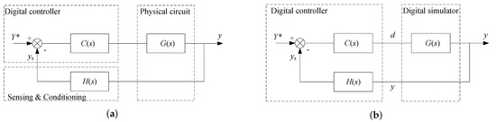
Figure 1.
Feedback control structure of simple dynamic systems: (a) digital controller with real plant; and (b) digital controller with simulated plant.
Comparing to commercial HIL simulators with dedicated graphical compiler and real-time monitoring interface, the proposed digital simulator establishes the plant model with c-coded difference equation sets. In the case of a switching system, the power converter circuit for example, the average model is used. In authors’ early research, as in Figure 1b, the control output from the digital controller d was the averaged PWM signal, generated from the on-chip DAC. The output signal y from the simulated plant is also from the on-chip DAC in the digital simulator. An early version of the hardware prototype is shown in Figure 2, where three dsPIC controllers are used with the third one managing the human machine interface.
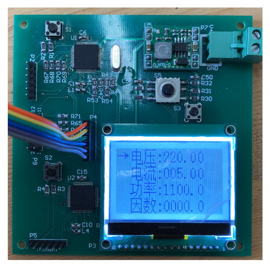
Figure 2.
Dual DSC prototype.
3. HIL-Based Teaching and Learning Model
For the HIL based teaching and learning, the students are required to work through seven steps, as listed below, which are graphically shown in Figure 3. Comparing to the conventional control oriented design and teaching without Steps 4 and 5, students or engineers with trouble in hardware debugging and testing could spend a lot of time to find the loop-holes in the design by starting from Step 2 again. With Steps 4 and 5, the errors in modeling and control can be fixed before going to the hardware debugging phase, which is sometimes time consuming and irreversible.
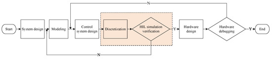
Figure 3.
Learning process based on HIL.
- System design, including the circuit analysis and parameter calculation
- Modeling
- Continuous control system design
- Discretization
- HIL simulation and verification
- Hardware design
- Hardware debugging and testing
In the commercial HIL system, Step 4 is done automatically by the compiler for graphical interface, while, in the proposed low-cost HILoC system, this step is conducted by the instructor and the student respectively.
The detailed model for the HIL based learning model is shown in Figure 4. The proposed HIL system featured with a dual-core DSC with support from auxiliary micro-controller for man-machine interface. The DSC CPU A, as the simulation engine, dedicates to circuit simulation with small simulation steps. The system excitation input or digital control routine is implemented in DSC CPU B, which is used as the control engine. Inter-processor communication is used to interchange variables between two CPUs. The system variables and control variables is isolated and conditioned through the signal conditioning circuit and sent to the oscilloscope for observation and debugging purpose.
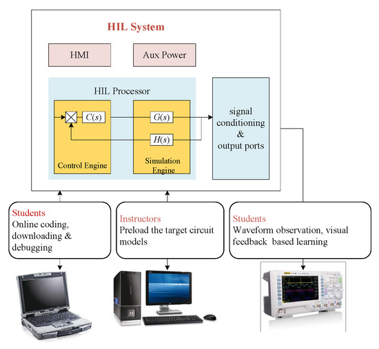
Figure 4.
HIL system structure and teaching model.
Considering the capability of the students, when the proposed HILoC is used for teaching, the sets of plant models are developed by the course instructor, which is preloaded into the simulation engine (CPU A). After finishing Step 3, the students discretize the controller, which is obtained previous step, and load the code into the control engine (CPU B). With no need to understand how the data exchange and plant modeling is done, the students only need to code the discretized controller into the designated sub-function and include it as the input file in the project.
Desired state variable and control variable can be captured in realtime on the oscilloscope screen for students’ visual feedback. The system performance indices such as the output overshot, setting times, and steady state error can be observed for control design iteration.
4. Dynamic System Modeling and Iteration
4.1. HIL Model of the Switching Systems
In this section, the plant modeling and iteration methods are presented. As stated in Section 3, due to limited hardware resource, switching state detection is not used in the proposed system. The average model is used instead. A buck converter, as shown in Figure 5, is chosen as the example to demonstrate the modeling and iteration process.
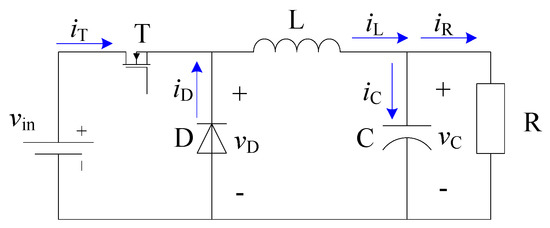
Figure 5.
Buck converter circuit.
are chosen as the state variables. When the switch T is turned on, the differential equation can be found using Equations (1) and (2)
while, for the switch off state, the system equation can be obtained by Equations (3) and (4)
To show the steady state load effect, the MOSFET switch on-state resistor and the inductor parasitic resistance are included in the equation. Applying the state-space averaging, the state equation including the switching function can be obtained as in Equations (5) and (6).
Discretization is applied to the plant equation, which runs in the simulation engine at high update rate . The accelerated iteration method is proposed in this HILoC system. As indicated in iteration equation, in the kth iteration, Equation (7) is calculated first, using the inductor current and capacitor voltage in the previous sampling period. Once the updated inductor current is obtained, it is substituted into the second half of the iteration, which is shown in Equation (8). The cross-update in one iteration results in faster variable convergence and improves the efficiency of the simulation.
Similarly, the boost converter’s continuous and discrete model can be obtained as in Equations (9) to (12)
4.2. HIL Model of Typical Process Systems
Basic process control systems are designed to meet a wide range of industrial challenges related to system operation and monitoring. A number of process control system can be modeled with continuous states and event-based inputs. A simple example of a process system is shown in Figure 6. In this classical two-container system, is the pipeline flow rate, is the value, is the liquid resistance of the value, is the cross-section area of the container, and is the liquid level, where .
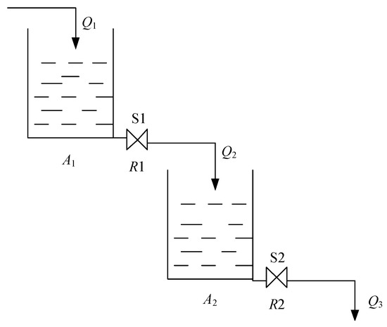
Figure 6.
Classical two container model.
Without considering the time delay of the pipeline in and out of the two tanks, Equations (13) and (14) can be obtained by applying Bernoulli’s principle.
By further applying discretization with the accelerated iteration method, the iteration difference equation can be implemented in the processor, as shown in Equations (15) and (16)
4.3. Discrete Model of the Digital Controller
In the control engine, the control routine is executed at a slower rate than that of the simulation engine, which is . In most design cases, single feedback loop is implemented. In this paper, a type-2 PI controller is used to demonstrate the feasibility of the HILoC design. By applying the bilinear transformation to Equation (17), the discretized controller iteration expression (Equation (18)) can be obtained.
5. Computation Routine and Data Exchange
The iteration process introduces sampling delay. Therefore, to emulate the plant effectively, the simulation steps is chosen to be much smaller than the equivalent system time constant. In the proposed system, the update rate of the simulated plant is chosen as . For the digital power electronic systems with limited switching frequency, the control routine serves at or below the switching frequency, the updating period of which is defined as .
As the simulation and control engine are both inside one DSC, the state and control variable exchange between two engines does not require interfacing circuitry or analog-to-digital peripherals. Inter-processor communication (IPC) protocol is used to send and fetch the variables between two CPUs. The proposed timing sequence of the data exchange is indicated in Figure 7. High resolution timers are used as the time-base to generate interrupt service routines (ISR) for both simulation and control engine. The plant model is iterated inside the simulation engine’s ISR running at a high refreshing rate of 5 s. Therefore, the state variable is considered realtime for both observation and the control purposes. The simulation and data exchange take place as per described in the chart. The digital control service is scheduled for every 50 s, which is divided into four phases:
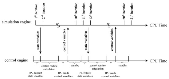
Figure 7.
Data exchange process in HIL system.
- Request state variables
- Calculate control routine
- Send control variables
- Idle time
At the beginning of the digital control service, the control engine initiates the state variable request through IPC. After the variables are obtained from the IPC buffer, digital control routine computation is performed to generate the control variable, the duty cycle, which is immediately sent to IPC buffer. The simulation engine picks up the control variable from IPC buffer at the beginning of the 5 s interrupt routine. Therefore, the control action is equivalent to the instantaneous duty cycle update mode in most of the commercial DSCs. Due to the digital nature of the simulated plant, the HILoC introduce an average delay time of 2.5 s to the system.
6. Experimental Verification
The proposed HIL system was implemented with Texas Instrument dual-core DSC TMS320F28379D (Texas Instruments, Dallas, TX, USA) as the computation hardware and Atmega328p (Microchip Technology, Chandler, AZ, USA) for system house-keeping. The prototype is shown in Figure 8, in which two analog and two PWM outputs are allocated for oscilloscope based observation. The specifications are listed in Table 1.
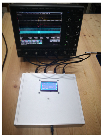
Figure 8.
Dual-core single DSC prototype.

Table 1.
HILoC system specifications.
To demonstrate the HILoC capability of simulation fast dynamic systems, two basic dc-dc topologies, the buck and boost converters, were modeled for system verification. Eight test session were proposed for both learning and design purposes, including the open-loop experiment for system dynamic behavior observation and close-loop design experiment.
Load disturbances, input disturbances and duty cycle perturbation are the input for three important transfer functions in modern switching power converter design, which are the output impedance, audio susceptibility, and the control to output transfer function. The step changes are implemented in the control engine while the circuit model is implemented in the simulation engine.
Figure 9 shows the simulation results for the open loop characteristics of a buck converter. As listed in Table 2, the load step disturbance, input voltage disturbance, and the duty cycle disturbance are verified with the HILoC hardware. Hardware simulation of the open loop characteristics of a boost converter is shown in Figure 10.
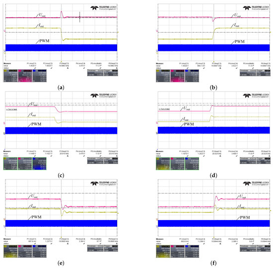
Figure 9.
Buck converter open-loop characteristics demonstration using proposed HILoC (a) load dump; (b) load increase step; (c) input voltage drop; (d) input voltage increase; (e) duty cycle step down; and (f) duty cycle step up.
Table 2.
Test condition.
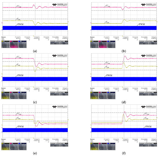
Figure 10.
Boost converter open-loop characteristics demonstration using proposed HILoC: (a) load dump; (b) load increase step; (c) input voltage drop; (d) input voltage increase; (e) duty cycle step down; and (f) duty cycle step up.
Figure 11 shows the close-loop interaction between the simulation engine and the control engine in the proposed HILoC system. The proposed HILoC system simulates the close-loop control under the load disturbance and the input voltage disturbance injection. As can be observed, the control engine can receive the voltage feedback from the simulation engine and perform PI control to the simulated plant. The analog and digital outputs of the HILoC will enable real-time close-loop performance evaluation and debugging. As mentioned above, the power converter under hardware simulation is implemented with the average model. The proposed HILoC still generates equivalent PWM signals to illustrate the duty cycle variation under the regulation period. Taking Figure 11b as an example, when the system is undergoing a step load increase, the system output drops due to the step discharge of the capacitor and the voltage drop along the feedforward path. One can easily observe from the test waveform that the control duty cycle increases slightly under close-loop control to compensate the voltage drop.
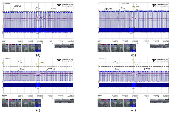
Figure 11.
Buck converter close-loop demonstration using proposed HILoC, 10 ms/grid: (a) load dump; (b) load increase step; (c) input voltage drop; and (d) input voltage increase.
With the proposed HILoC, the students or the engineers can easily modify the control parameter to observe the system performance. Figure 12 shows the hardware simulation results of voltage controlled buck converter with different and parameters in a traditional PI controller. The regulation performance is clearly demonstrated using the proposed HILoC system.
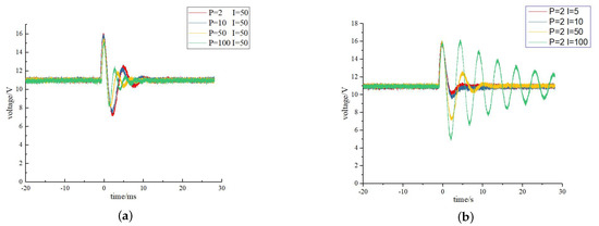
Figure 12.
Demonstration of control parameter sensitivity: (a) voltage regulation by sweeping proportional gain; and (b) voltage regulation by sweeping integral gain.
A comparison was conducted with the commercial HIL system, the Typhoon. The system was tested under the load step dynamic situation. As can be observed in Figure 13, the two system showed very close dynamic performance, which indicates the effectiveness of the proposed HILoC system.
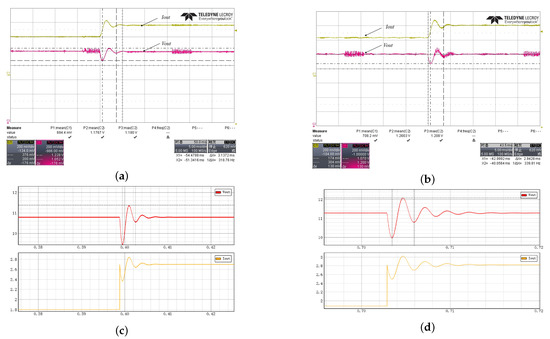
Figure 13.
Buck converter case study comparison: (a) HILoC load increase step open loop response; (b) HILoC close loop control with load increase step; (c) Typhoon open loop load increase step; and (d) Typhoon close loop control with load increase step.
A dual-tank process system with all continuous states is also verified with the proposed HILoC. The system parameter is scaled such that the simulation can be accomplished with in 100 s. From the beginning, all the valves are closed; the liquid is pumped into tank 1 continuously. The liquid fills tank 1 by 10 s and keeps running over. The operator opens at 15 s to release the liquid into tank 2. Since remains closed, tank 2 is filled and the liquid keeps running over tank 2. The operator opens at 30 s to release the liquid from tank 2. As expected, the liquid level of tank 2 drops, and the system eventually goes to the steady state. At 80 s, the system input is cut-off, all the tanks are drained. The simulation engine of the proposed HILoC simulates the dual tank plant, and the control engine launches different events, including , , and . The hardware simulation results is indicated in Figure 14a, which matches the computer simulation results in Figure 14b.
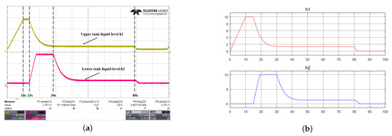
Figure 14.
Dual-container process system: (a) HILoC simulation results; and (b) MATLAB simulation results.
7. Conclusions
This paper proposes a low-cost Hardware-in-the-Loop on Chip (HILoC) platform for dynamic systems, especially for teaching and designing of digital power converters. The dual-core DSC solution is proposed. Critical issues of modeling implementation, inter-processor information exchange, and fast iteration are presented in detail in this paper. A full demonstration using the HILoC prototype is carried out for the buck and boost topology as well as a dual-tank process control system. The proposed low-cost HILoC system can be easily applied to the engineering teaching as well as fast prototype development phase of product design.
Author Contributions
Conceptualization, W.J.; methodology, W.J. and H.M.; software and validation, L.S. and Y.C.; resources, W.J. and S.H.; writing—original draft preparation, W.J. and L.S.; writing—review and editing, W.J.; visualization, S.H.; supervision, W.J.; project administration, W.J.; and funding acquisition, W.J. and S.H. All authors have read and agreed to the published version of the manuscript.
Funding
Yangzhou city-Yangzhou University Joint Fund (YZ2020169).
Conflicts of Interest
The authors declare no conflict of interest.
References
- Ren, W.; Steurer, M.; Baldwin, T.L. Improve the stability and the accuracy of power hardware-in-the-loop simulation by selecting appropriate interface algorithms. IEEE Trans. Ind. Appl. 2008, 44, 1286–1294. [Google Scholar] [CrossRef]
- Mai, X.H.; Kwak, S.; Jung, J.; Kim, K.A. Comprehensive electric-thermal photovoltaic modeling for power-hardware-in-the-loop simulation (phils) applications. IEEE Trans. Ind. Electron. 2017, 64, 6255–6264. [Google Scholar] [CrossRef]
- Goni, O.; Sanchez, A.; Todorovich, E.; Castro, A. Resolution analysis of switching converter models for hardware-in-the-loop. IEEE Trans. Ind. Inform. 2014, 10, 1162–1170. [Google Scholar] [CrossRef]
- Marks, N.D.; Kong, W.Y.; Birt, D.S. Stability of a switched mode power amplifier interface for power hardware-in-the-loop. IEEE Trans. Ind. Electron. 2018, 65, 8445–8454. [Google Scholar] [CrossRef]
- Jha, K.; Mishra, S.; Joshi, A. Boost-amplifier-based power-hardware-in-the-loop simulator. IEEE Trans. Ind. Electron. 2015, 62, 7479–7488. [Google Scholar] [CrossRef]
- Fernandez-alvarez, A.; Portela-Garcia, M.; Garcia-Valderas, M.; Lopez, J.; Sanz, M. HW/SW co-simulation system for enhancing hardware-in-the-loop of power converter digital controllers. IEEE J. Emerg. Sel. Top. Power Electron. 2017, 5, 1779–1786. [Google Scholar] [CrossRef]
- Sanchez, A.; Castro, A.; Garrido, J. A comparison of simulation and hardware-in-the- loop alternatives for digital control of power converters. IEEE Trans. Ind. Inform. 2012, 8, 491–500. [Google Scholar] [CrossRef]
- Riccobono, A.; Liegmann, E.; Pau, M.; Ponci, F.; Monti, A. Online parametric identification of power impedances to improve stability and accuracy of power hardware-in-the-loop simulations. IEEE Trans. Instrum. Meas. 2017, 66, 2247–2257. [Google Scholar] [CrossRef]
- Zhang, Y.; Xiong, R.; He, H.; Shen, W. Lithium-ion battery pack state of charge and state of energy estimation algorithms using a hardware-in-the-loop validation. IEEE Trans. Power Electron. 2017, 32, 4421–4431. [Google Scholar] [CrossRef]
- Roinila, T.; Messo, T.; Luhtala, R.; Scharrenberg, R.; Jong, E.C.W.; Fabian, A.; Sun, Y. Hardware-in-the-loop methods for real-time frequency-response measurements of on-board power distribution systems. IEEE Trans. Ind. Electron. 2019, 66, 5769–5777. [Google Scholar] [CrossRef]
- Edrington, C.S.; Steurer, M.; Langston, J.; El-Mezyani, T.; Schoder, K. Role of power hardware in the loop in modeling and simulation for experimentation in power and energy systems. Proc. IEEE 2015, 103, 2401–2409. [Google Scholar] [CrossRef]
- Liu, Y.; Steurer, M.; Ribeiro, P. A novel approach to power quality assessment: Real time hardware-in-the-loop test bed. IEEE Trans. Power Deliv. 2005, 20, 1200–1201. [Google Scholar] [CrossRef]
- Luo, K.; Shi, W.; Chi, Y.; Wu, Q.; Wang, W. Stability and accuracy considerations in the design and implementation of wind turbine power hardware in the loop platform. CSEE J. Power Energy Syst. 2017, 3, 167–175. [Google Scholar] [CrossRef]
- Tian, J.; Liu, J.; Shu, J.; Tang, J.; Yang, J. Engineering modelling of wind turbine applied in real-time simulation with hardware-in-loop and optimising control. IET Power Electron. 2018, 11, 2490–2498. [Google Scholar] [CrossRef]
- Huerta, F.; Tello, R.L.; Prodanovic, M. Real-time power-hardware-in-the-loop implementation of variable-speed wind turbines. IEEE Trans. Ind. Electron. 2017, 64, 1893–1904. [Google Scholar] [CrossRef]
- Jandaghi, B.; Dinavahi, V. Hardware-in-the-loop emulation of linear induction motor drive for maglev application. IEEE Trans. Plasma Sci. 2016, 44, 679–686. [Google Scholar] [CrossRef]
- Tavana, N.R.; Dinavahi, V. Real-time nonlinear magnetic equivalent circuit model of induction machine on fpga for hardware-in-the-loop simulation. IEEE Trans. Energy Convers. 2016, 31, 520–530. [Google Scholar] [CrossRef]
- Yang, X.; Yang, C.; Peng, T.; Chen, Z.; Liu, B.; Gui, W. Hardware-in-the-loop fault injection for traction control system. IEEE J. Emerg. Sel. Top. Power Electron. 2018, 6, 696–706. [Google Scholar] [CrossRef]
- Alvarez-Gonzalez, F.; Griffo, A.; Sen, B.; Wang, J. Real-time hardware-in-the-loop simulation of permanent-magnet synchronous motor drives under stator faults. IEEE Trans. Ind. Electron. 2017, 64, 6960–6969. [Google Scholar] [CrossRef]
- Syed, M.H.; Guillo-Sansano, E.; Wang, Y.; Vogel, S.; Palensky, P.; Burt, G.M.; Xu, Y.; Monti, A.; Hovsapian, R. Real-Time Coupling of Geographically Distributed Research Infrastructures: Taxonomy, Overview, and Real-World Smart Grid Applications. IEEE Trans. Smart Grid 2021, 12, 1747–1760. [Google Scholar]
- Palmintier, B.; Lundstrom, B.; Chakraborty, S.; Williams, T.; Schneider, K.; Chassin, D. A power hardware-in-the-loop platform with remote distribution circuit cosimulation. IEEE Trans. Ind. Electron. 2015, 62, 2236–2245. [Google Scholar] [CrossRef]
- Cale, J.L.; Johnson, B.B.; Dallanese, E.; Young, P.M.; Duggan, G.; Bedge, P.A.; Zimmerle, D.; Holton, L. Mitigating communication delays in remotely connected hardware-in-the-loop experiments. IEEE Trans. Ind. Electron. 2018, 65, 9739–9748. [Google Scholar] [CrossRef]
- Wang, Y.; Nguyen, T.L.; Syed, M.H.; Xu, Y.; Guillo-Sansano, E.; Nguyen, V.H.; Burt, G.M.; Tran, Q.T.; Caire, R. A Distributed Control Scheme of Microgrids in Energy Internet Paradigm and Its Multisite Implementation. IEEE Trans. Ind. Inform. 2021, 17, 1141–1153. [Google Scholar] [CrossRef]
- Abdelrahman, A.S.; Algarny, K.S.; Youssef, M.Z. A novel platform for powertrain modeling of electric cars with experimental validation using real-time hardware in the loop (hil): A case study of GM second generation chevrolet volt. IEEE Trans. Power Electron. 2018, 33, 9762–9771. [Google Scholar] [CrossRef]
Publisher’s Note: MDPI stays neutral with regard to jurisdictional claims in published maps and institutional affiliations. |
© 2021 by the authors. Licensee MDPI, Basel, Switzerland. This article is an open access article distributed under the terms and conditions of the Creative Commons Attribution (CC BY) license (http://creativecommons.org/licenses/by/4.0/).