1. Introduction
The propagation characteristics in some sophisticated periodic structures have been subject to investigation from many researchers in the past few years because of their wide field of application in microwave and optical communication systems, associated with their frequency-selective behavior. Some common examples of periodic structures are photonic crystals [
1] and frequency-selective surfaces (FSSs) [
2,
3,
4]. Within the second type of periodic structures, we can find the so-called dielectric frequency-selective surfaces (DFSSs) [
5,
6,
7], which, unlike classical metallic FSSs—metallic surfaces showing some periodicity on the surface—consist of multilayered dielectric planar slabs containing a periodic variation along any layer. In such structures, leaky modes can be generated in suitable geometries and produce total reflection at the resonance frequencies. These guided-mode resonance structures have been of considerable interest as passive signal processing devices with a large number of applications. A few of these possible uses include static and tunable spectral filters with arbitrarily narrow bandwidths, optical switches and modulators, polarizers, couplers, sensors, dichroic subreflectors in antennas, and many other applications [
8,
9,
10,
11].
In order to obtain the dispersion behavior in DFSSs, which are multilayered planar structures where at least one propagating medium is a periodic dielectric grating formed by two or more dielectric slabs, under plane-wave incidence, the modal spectrum in all propagating media must be efficiently computed. For this analysis, some authors have employed semi-analytical methods [
12]. However, when the number of dielectric slabs inside the propagation medium increases, alternative methods should be employed, with the ones that are more used including the modal, perturbative [
13], transfer-matrix [
14] or numerical methods such as finite difference time domain (FDTD) method [
15] and finite-element method [
16]. However, the combination of the periodic characteristics of DFSSs together with their open nature makes it difficult to employ some commercial electromagnetic software based on numerical methods (such as Ansys HFSS or CST) for their analysis. Alternatively, modal methods, which are more suitable from a computational point of view, may be performed by using either full-vectorial treatments [
17] or approximate scalar approaches [
18]. Scalar modal methods have two fundamental problems: on the one hand, they lack general applicability and, on the other hand, they do not take into account the vector nature of the electromagnetic fields. Thus, vectorial modal methods are much more suitable because of their efficiency and accuracy. Additionally, the proposed method is especially indicated for analyzing dielectric discontinuities including multiple lossy dielectrics with periodic boundary conditions, such as the ones present in DFSSs, in which other traditional methods may lack the necessary accuracy.
In this work, we will focus on a full-vectorial modal method [
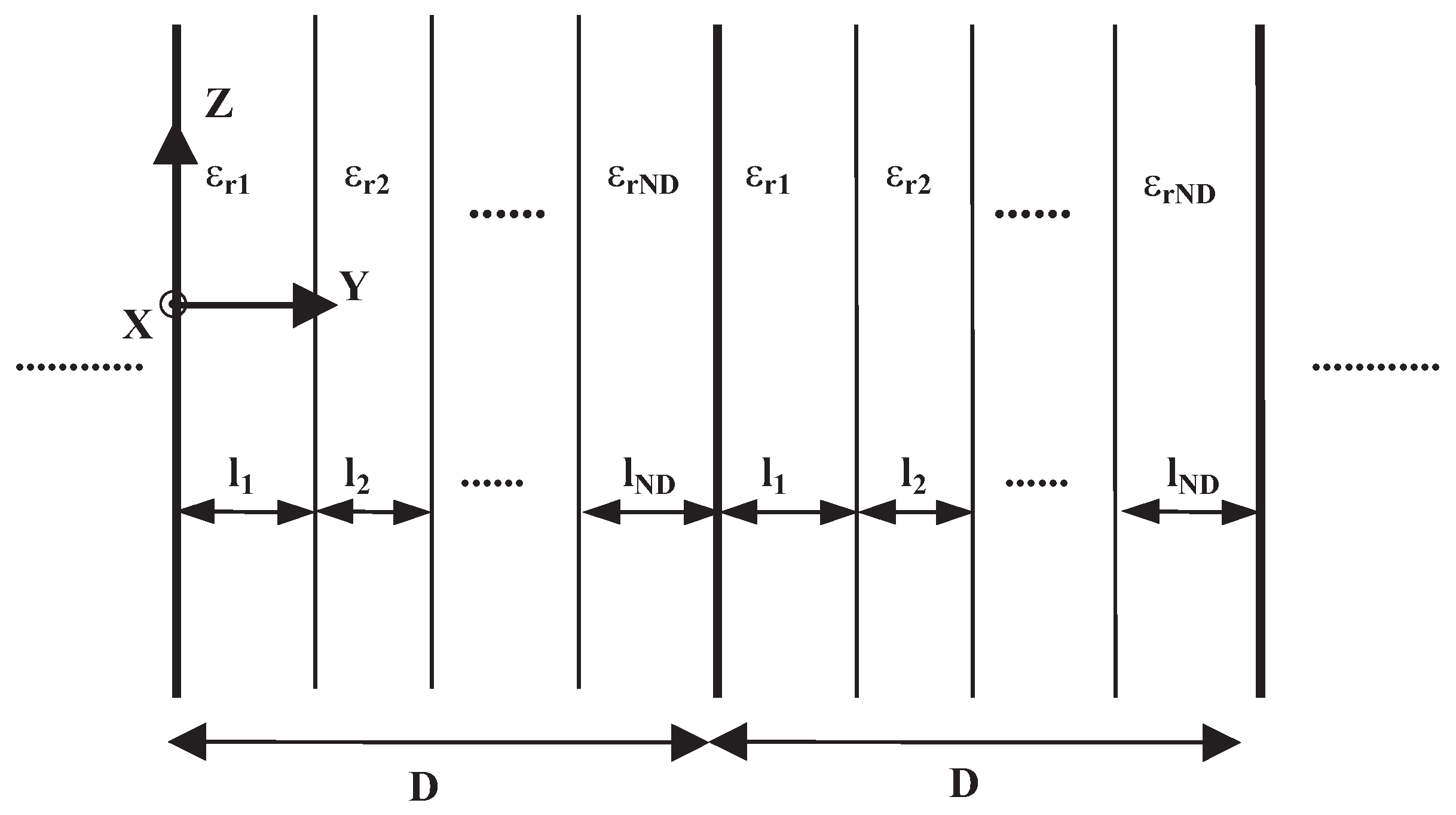
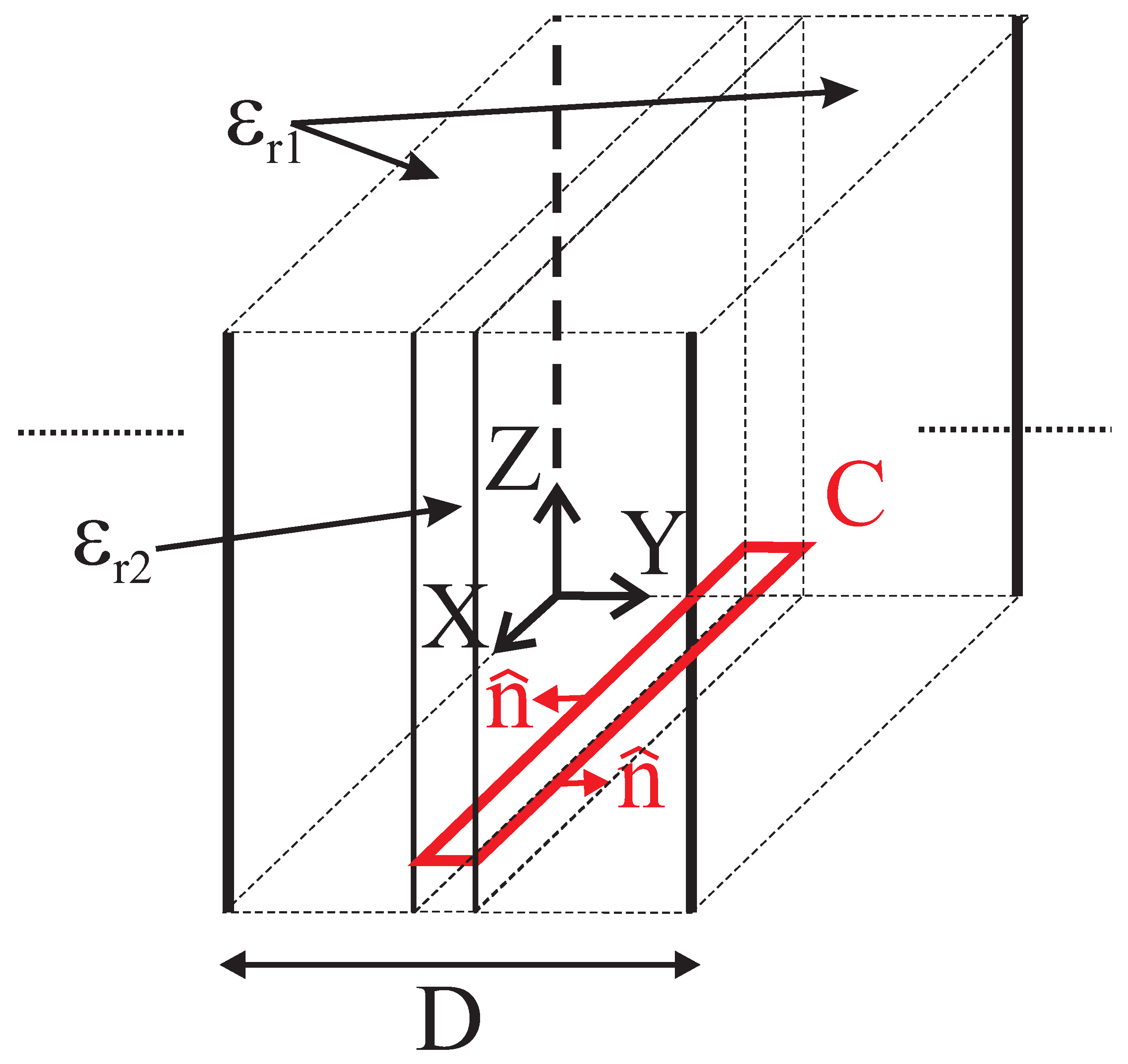
6] based in the Method of Moments (MoM), in which integrals involving discontinuities of a component of the electromagnetic field must be evaluated. These integrals contain the relative dielectric permittivity function, which is a discontinuous function, and its transverse gradient. Some confusion may exist regarding the evaluation of these integrals, due to the discontinuous nature of the dielectric function and its transverse gradient. Thus, in this paper, we study the way to solve these integrals accurately for the general case of a relative dielectric permittivity function defined as a sum of lossy dielectric slabs in the unit cell of a periodic dielectric medium, as is the case in DFSSs. To this end, we analyze a simple case of a dielectric slab surrounded by a different dielectric medium inside the unit cell of the periodic dielectric medium (see
Figure 1), whose contour defines the discontinuity, so it can be expressed in terms of the Heaviside or step function. In this way, these integrals have been correctly evaluated regarding their discontinuity, giving good results for the propagation constant and the fields obtained with the vectorial modal method. These results are compared with those obtained using a less accurate evaluation of the cited integrals, when an approximation made by other authors is employed [
19,
20,
21], and also with results obtained with a completely numerical approach adopted for numerical validation (Ansys HFSS), demonstrating the accuracy of the proposed method and revealing a significant higher efficiency in terms of computation time.
The rest of the document is organized as follows.
Section 2 is dedicated to describe the theoretical base of the full-vectorial modal method and to evaluate the integrals involving the discontinuity. Next,
Section 3 shows, for a simple case, a comparison of the results of the evaluation of these integrals when they are correctly evaluated with those obtained using a wrong approximation. Results concerning the propagation constant obtained in both cases for some propagating modes are also presented, along with some field components for this case. Finally,
Section 4 summarizes the main conclusions that can be drawn from this work.
2. Theory
The objective of this section is to present the theoretical bases of the vectorial modal method for studying a dielectric one-dimensional periodic medium in the
Y direction with translational invariance along the
Z axis (see
Figure 1). We assume that the magnetic field in this medium can be expressed as a linear superposition of fields with explicit harmonic dependence on the
z coordinate (we assume that the time dependence is always implicit and has an harmonic form
for all vector fields):
where
is the propagation constant,
represents the transverse component to the
Z direction of the magnetic field, and
is the component in the
Z direction. Following [
22], it can be derived that the transverse component of the magnetic field, when no sources are present, satisfies the vector wave equation [
5,
6]:
where
is the relative complex permittivity of the periodic medium,
is the free-space wavenumber
, and
and
are the transverse gradient and transverse laplacian operators, respectively. In this equation, we can identify in square brackets the differential operator governing the transverse component evolution along the
Z axis.
For our purposes, it is more interesting to rewrite Equation (
2) as a pure 2D eigenvalue problem for the differential evolution operator
L:
where
is the eigenvector of the
L operator. We are certainly concerned with the matrix representation of the linear operator
L. Following the standard Method of Moments [
23], this eigenvalue equation can be expressed in a matrix form if the modes in the periodic medium are expanded in terms of an auxiliary system whose eigenvectors satisfy an orthogonality relation of the form:
Thus, the modes of the real problem can be expanded in terms of the auxiliary system as:
where
are the complex coefficients of the modal expansion for the transverse magnetic field of the
n-th mode. Finally, the transverse electric fields of the modes are related to the magnetic ones through constraints directly derived from Maxwell’s equations [
22], resulting in:
For the auxiliary system, we used the Floquet modes corresponding to a lossless homogeneous medium of relative dielectric permittivity
and periodicity
D—i.e., the eigenfunctions of the evolution operator
corresponding to a periodic structure immersed in a lossless homogeneous medium [
24]—. Such modes have been adequately normalized to satisfy the following orthogonality relationship:
where
represents, in this case, the cross section of the periodic cell. Then, the application of the Method of Moments yields the following linear matrix eigenvalue problem:
where
are the matrix elements of the
L operator, which are obtained as follows (it is worth noting that the standard Galerkin’s procedure was not employed):
By breaking down the problem under consideration to
, each element
of the matrix can be calculated by means of the expression:
where the first term is diagonal because the operator
is expressed in its own orthogonal basis.
Given that we have chosen as the auxiliary basis the Floquet modes of a lossless homogeneous medium of relative dielectric permittivity and periodicity D, in this case we obtain . The diagonalization process provides us with the eigenvectors and eigenvalues of the L-matrix. The former give us the amplitudes of the transverse magnetic components of the waveguide modes. The latter yield their corresponding propagation constants in the form of their squares .
For the particular case of a periodic dielectric medium with an arbitrary number of dielectric slabs inside the periodic cell, the medium can be fully characterized by its complex relative permittivity in the unit cell, defined as:
where
is the Heaviside or step function,
is the number of lossy dielectric slabs inside the periodic cell (which can be an arbitrary number), and the
i-th dielectric slab is centered at point
, being
its width, as shown in
Figure 1.
As described in
Section 1, some confusion may exist in the evaluation of the one-dimensional integrals that appear in the calculation of the L-matrix (see Equation (
10)), when the relative dielectric permittivity is a discontinuous function; this may even apply to the simpler case of two dielectric slabs in the periodic cell of relative permittivities
and
(see
Figure 2), as will be analyzed in
Section 3, defined as a Heaviside function—i.e., it has a constant value of
and
in and outside of a domain of definition delimited by the contour
C—. For convenience, we will choose a curvilinear coordinate system [
25] defined by the curvilinear coordinates
, being
n and
, respectively, the normal and tangential coordinates to the contour
C, and
z coinciding with the Cartesian coordinate. In this coordinate system, both the relative permittivity and its gradient may be expressed as follows:
where we have chosen
, being
and
, respectively, the
normal scale factor and theunit vector normal to the curve
C in the normal-tangential coordinate system, and
a normal coordinate above the curve.
The surface element
in the
z direction in the normal-tangential coordinate system takes the form:
where
is the
tangential scale factor.
The first integral of Equation (
10) can be easily evaluated and we will not go into detail. Precisely the second integral of Equation (
10) is the one which may have some difficulty in its evaluation, because a gradient of a discontinuous function must be calculated. Moreover, we will show that it can be reduced to a contour integral. By substituting Equations (
12)–(
14) in the second integral of Equation (
10), we find:
Now, making use of a property of the vector triple product, we can rewrite Equation (
15) as follows:
where
is the normal component of the transversal electric field. Next, we can transform the surface integral into a contour one, just making use of the fundamental defining property of the delta function, which states that:
This works provided that the range of integration includes the point
. In our case, the integration in
n can be reduced by evaluating the integrand in
:
The following step is the evaluation of the Heaviside function just in the discontinuity. This can be solved by approximating the step function by a continuous function that, in the limit, coincides with the Heaviside function [
26], which is:
Next, we have to evaluate the inverse of the relative permittivity function just in the step, resulting in:
Substituting this result in Equation (
18), we have the final expression for the second integral of Equation (
10):
A different result is obtained if we evaluate the term
, expressed as
, as in [
19,
20,
21]. In this case, the evaluation of the second integral of Equation (
10) proceeds as follows:
As will be shown in next section, the results obtained using Equation (
22) will be more accurate than those obtained using the approximation described by Equation (
23).
3. Numerical Results and Discussion
In this section, we apply the above theory to a simple case: it consists of a 1D periodic dielectric medium of period
D formed by a dielectric slab of width
and
, placed in a centered position (
) inside a periodic cell of relative permittivity
. For this case, the relative permittivity function inside the periodic cell is expressed as follows:
where
,
, and
and
are the normal coordinates above the curve
C, which in this case coincide with the straight lines
and
(i.e., one tenth of the periodic cell is filled with dielectric material whose relative permittivity is
).
In order to verify that the second-order integral has been correctly evaluated using Equation (
22), it has also been numerically calculated employing, for the relative permittivity function, the continuous function described in Equation (
19):
where
,
,
and
take the same value as in Equation (
24).
In
Figure 3, we show the relative dielectric permittivity function for different values of the parameter
s. It can be checked that, in this case, the relative permittivity function is very well approximated by the continuous function defined in Equation (
25) using a value of
. In the problem under consideration, we have chosen a working frequency of 10 GHz, and we have taken the Floquet modes under normal incidence of a homogeneous medium of relative permittivity
and periodicity
D as the auxiliary basis in the calculation of the L-matrix. In
Table 1, we present the relative difference between the result obtained for an element (in particular,
) of the second integral in Equation (
10) employing the function of Equation (
25), with respect to that obtained using Equation (
22) for different values of the parameter
s. Obviously, as the parameter
s increases, the relative difference rapidly decreases.
Now, we will analyze the effect of the dielectric permittivity in the deviation of the value of the second integral in Equation (
10) when it is not correctly evaluated. To this end, we have plotted, in
Figure 4, the deviation of the constant factors appearing out of the integral in Equations (
22) and (
23), which are obtained by evaluating the term
or the term
, as a function of the difference of the relative dielectric permittivity
. For small differences in the relative dielectric permittivity, the deviation is not important, but as the difference becomes higher, the deviation between both results becomes significant.
Finally, we want to show the effect of the evaluation of the integrals in the discontinuity in both the propagation constant and the fields, when the second integral of Equation (
10) is evaluated as in Equation (
22), or by using the result of Equation (
23). To this end, we chose the same example that was previously described in Equation (
24), with parameters
,
,
and
, again under normal plane-wave incidence.
Table 2 displays the normalized propagation constant
of the two modes which are propagative at the working frequency of 10 GHz, the first one being a mode with TE polarization, while the second mode has a TM polarization. We compare the results obtained with the vectorial modal method for both ways of evaluating the discontinuity (as in Equation (
22) or by using the result of Equation (
23)), considering 30 vector mode functions as the auxiliary basis in the calculation of the L-matrix for reaching the convergence (in this case, with a 0.5% relative error). Such results are also compared with those numerically obtained with Ansys HFSS, for which the computation time was two orders of magnitude greater in the same machine, thus highlighting the advantage of the present vectorial modal method in terms of efficiency. We also represent, in
Figure 5, the y-component of the transverse electric field for the first propagative TM mode in this structure.
At the sight of
Table 2, as one could expect for a great difference in the relative permittivity, in the case of the second mode (the TM mode) the results obtained employing the logarithm clearly deviate from the results obtained with Ansys HFSS, showing that the integrals were not correctly evaluated. This does not occur when the integrals are computed following Equation (
22), giving a very good agreement. Nevertheless, this difference between the results for both ways of evaluating the discontinuity is only characteristic of the family of TM modes, with the result obtained by both methods for the TE modes being nearly the same.
Thus, for the TE modes the results obtained in the diagonalization by both methods coincide with the value obtained with Ansys HFSS, whereas for the TM modes we get a better agreement by following the development derived in Equation (
22). This behavior can be understood as follows: for TM modes, the transverse electric field (which is represented in
Figure 5) is normal to the dielectric interface, being consequently discontinuous, which is a direct consequence of the discontinuity in the dielectric permittivity, while the electric displacement vector must be a continuous function along the dielectric interface. On the other hand, the transverse electric field for TE modes is continuous, because the nature of this family of modes forces the normal component of the electric field (the y-component for our case), which should be discontinuous, to be equal to zero, which makes the second integral in Equation (
10) vanish in this case.
In
Figure 6, we plot the electric displacement vector for the first TM mode when following the development in Equation (
22), showing that it is a continuous function along the dielectric interface.
It is worth mentioning that, when conical incidence is considered (i.e., the incidence of a plane-wave with arbitrary angles
and
) [
27], the second integral in Equation (
10) will no longer vanish, and thus the evaluation of the dielectric discontinuities must be properly conducted following the development provided in Equation (
22).


