Article

A 5-Bit X-Band GaN HEMT-Based Phase Shifter

1
Department of Electronic Engineering, Chang Gung University, Tao-Yuan 33302, Taiwan
2
Department of Materials Engineering, Ming Chi University of Technology, New Taipei 243303, Taiwan
3
Center for Thin Film Technologies and Applications, Ming Chi University of Technology, New Taipei 243303, Taiwan
4
Centre for Reliability Sciences and Technologies, Chang Gung University, Tao-Yuan 33302, Taiwan
5
Department of Dermatology, Chang Gung Memorial Hospital, Linkou Branches, Tao-Yuan 33305, Taiwan
*
Author to whom correspondence should be addressed.
Electronics 2021, 10(6), 658; https://doi.org/10.3390/electronics10060658
Submission received: 9 February 2021 / Revised: 25 February 2021 / Accepted: 9 March 2021 / Published: 11 March 2021
(This article belongs to the Section Microelectronics)

Abstract

:
In this study, we propose a 5-bit X-band gallium nitride (GaN) high electron mobility transistor (HEMT)-based phased shifter monolithic microwave integrated circuit for a phased-array technique. The design includes high-pass/low-pass networks for the 180° phase bit, two high-pass/bandpass networks separated for the 45° and 90° phase bits, and two transmission lines based on traveling wave switch and capacitive load networks that are separated for the 11.25° and 22.5° phase bits. The state-to-state variation in the insertion loss is 11.8 ± 3.45 dB, and an input/output return loss of less than 8 dB was obtained in a frequency range of 8–12 GHz. Moreover, the phase shifter achieved a low root mean square (RMS) phase error and RMS amplitude error of 6.23° and 1.15 dB, respectively, under the same frequency range. The measured input-referred P1dB of the five primary phase shift states were larger than 29 dBm at 8 GHz. The RMS phase error and RMS amplitude error slightly increased when the temperature increased from 25 to 100 °C. The on-chip phase shifter exhibited no dc power consumption and occupied an area of 2 × 3 mm2.

1. Introduction

The phased-array technology has been developed for decades in military and radar applications [1,2,3]. This technology is used for electronic steering, thereby improving the speed and reliability of a mechanically steered antenna. Figure 1 shows a schematic diagram of a radiofrequency (RF) beamforming. The direction of each antenna element can be electronically controlled by a phase shifter to create a beam with the required phase or amplitude without moving the antennas. Beamforming can be achieved by combining the elements in the antenna array to obtain the desired pattern shape. The phase shifter is the core element of phase array systems that enables these systems to provide fast and accurate beam steering. Many process technologies such as p-i-n (PIN) diode, Gallium Arsenide (GaAs), and complementary metal-oxide-semiconductor (CMOS) are used to fabricate phase shifters. The use of PIN diodes in phase shifters offers high-power handling capability, but its large forward current in the on-state leads to power dissipation, which remains a challenge [4,5,6]. The use of GaAs-based and silicon-based phase shifters is limited by the RF power handling capability because of their small breakdown voltage although they have high integration [7,8,9,10]. Nowadays, gallium nitride (GaN) high-electron-mobility transistors have a high current density (~1.5 A/mm), high breakdown voltage (>600 V), and high temperate operation (~600 °C) due to the inherent characteristics of their wide band gap (~3.4 eV). Because a large amount of phase shifters are required for a phase array system, a GaN high electron mobility transistor (HEMT)-based monolithic microwave integrated circuit (MMIC) is a good candidate to provide single-chip transmitter/receiver modules with high-power handling capability and good reliability [11,12,13].
Several topologies of phase shifters have been proposed, such as the switched-line [14], reflection [15], loaded-line [16,17], and low-pass/high-pass [18,19]. Loaded-line and reflection topologies are useful for small phase shifts (<45°) because of their good phase accuracy, but they exhibit a limited bandwidth and chip size at low frequency. The loaded-line and reflection are useful for small phase shift because the accuracy phase but limited bandwidth and chip size at low frequency. Although the switched-line shifter has a wide band characteristic, its large area is not suitable for MMIC. Low-pass/high-pass topologies provide a wide bandwidth and a flat phase response because the phase effects from switching and routing can be cancelled. In addition, a transistor as a switch can be integrated into the filter to make its size compact and enable it to achieve large phase shift values. However, the narrow range and parasitic effect of passive devices such as the inductor or capacitor that are implemented on the wafer results in an additional challenge for high/low-pass filters.
To improve the performance of the phase shifter, this paper reports an X-band 5-bit phase shifter fabricated using a 0.25 μm AlGaN/GaN HEMT-on-SiC process. The proposed 5-bit phase shifter consists of high-pass/low-pass networks, two high-pass/bandpass networks, and two transmission lines based on traveling wave switch and capacitive load networks, which are arrangement for the 180°, 45° and 90°, and 11.25° and 22.5°-phase bits, respectively. The high-/low-pass network is used for the 180° phase bit for a flat phase response. For the bandpass topology, the signal passed from the input to the output ports without via passive devices to improve the insertion loss. A transmission line based on traveling wave switch and capacitive load was used for the small phase bit to achieve an accurate phase. The phase shifter provides 32 phase shift states between 0° and 360° in increments of 11.25°. Although the networks in each phase bit are conventional, this is the first time to combine them for 5-bit GaN-based phase shifter to achieve low root mean square (RMS) phase error and compact size. The phase shifter demonstrates an RMS phase error and RMS amplitude error of less than 4.84° and 0.67 dB, respectively, over a frequency range of 8–11.5 GHz. The lowest 2.52° RMS phase error at 11 GHz was obtained because the transmission line by traveling wave switch concept provides accurate phase. A better power handling capability was achieved at 8 GHz compared to that at 29 dBm for the five major states. GaN-MMIC phase shifters have the potential to provide low loss, low power, and high-power handling for next-generation wireless communication systems.

2. Circuit Design

2.1. High/Low-Pass Phase Shifter

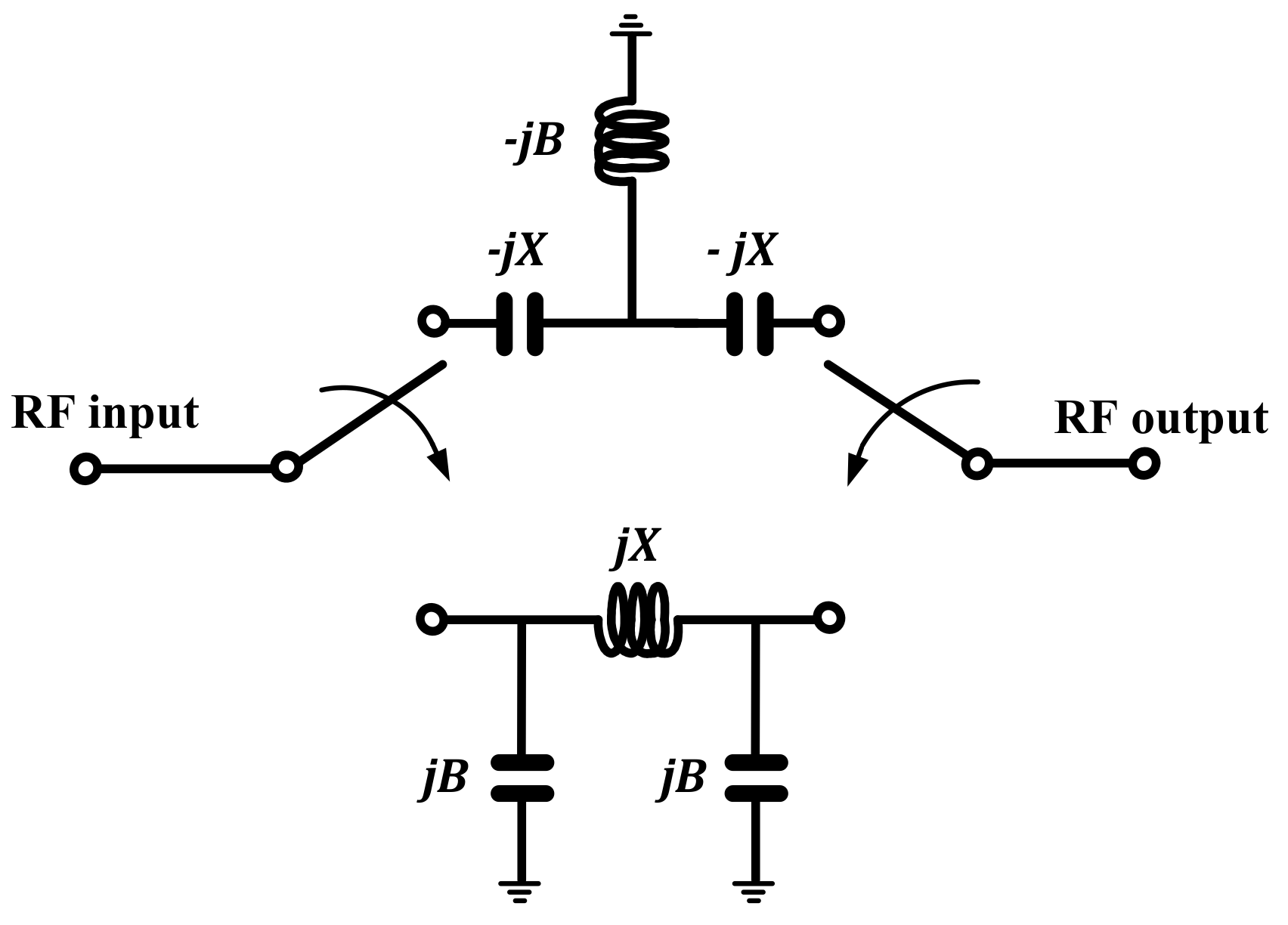
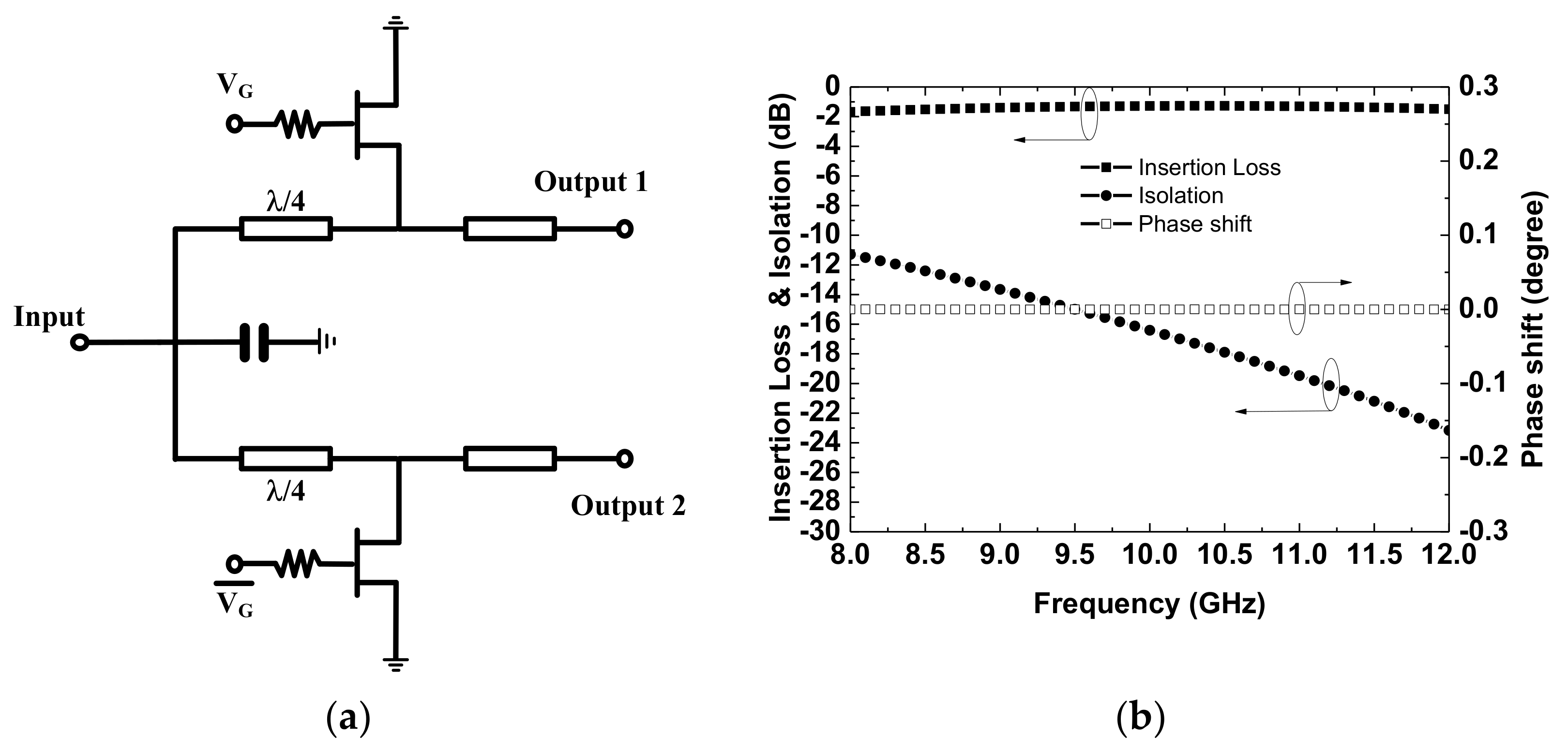
Figure 2 shows the schematic of a high-/low-pass phase shifter using T— and Π—configurations. High-/low-pass topologies consist of series and shunt inductors and capacitors to provide a compact size and large bandwidth for the phase shifter. Two single-pole/double-throw (SPDT) switches, which are located separately on both sides of the high/low pass filters, are used to select the high- or low-pass paths. The GaN HEMT has a large drain-source capacitance, which causes poor isolation for series switch topology. In addition, the insertion loss degradation and switch compression by traps for GaN HEMT should be carefully considered at increasing values of drain and gate voltages for series switch topology [20]. Therefore, the shunt switch topology connected with a quarter wavelength transmission line between the output port and the shunt transistor is used in Figure 3a. The switching GaN HEMTs are modeled as a low resistor in on state and a large capacitor in off state. Figure 3b shows the simulated insertion loss, isolation, and phase shift between on and off states of the SPDT with 2 × 125 μm HEMT. The insertion loss is 1.47 ± 0.2 dB, the isolation is less than −11.3 dB, and the phase shift is almost 0° from 8 to 12 GHz.
The high-pass topology and low-pass topology create the positive and negative phases, respectively, which serve as the reference and delay circuit, respectively. The ABCD matrices for the switch in the high-pass state are written as [21]:
A B C D = 1 j X 0 1 × 1 0 j B 1 × 1 j X 0 1 = 1 B X j 2 X B X 2 j B 1 B X ,
where X is the reactance and B is the susceptance of the capacitor and inductor in the high-pass state in Figure 1. The ABCD parameters convert into scattering parameters. The insertion loss can then be obtained by:
S 21 = 2 2 1 B X + j B + 2 X B X 2 .
The phase shift Δϕ caused by the switching between the high-pass and low-pass topologies is given by [11]:
Δ ϕ = 2 t a n 1 B X 2 2 X B 2 1 B X .
The phase shift is doubled because of the switching of the low- and high-pass paths. B and X change signs when switching from a high-pass to a low-pass. For a matched lossless, B and X can be determined to be:
X = tan Δ ϕ 4 ,
B = sin Δ ϕ 2 .
High-pass/low-pass networks are used for the 180° phase bit to reduce the chip size.

2.2. High/Band-Pass Phase Shifter

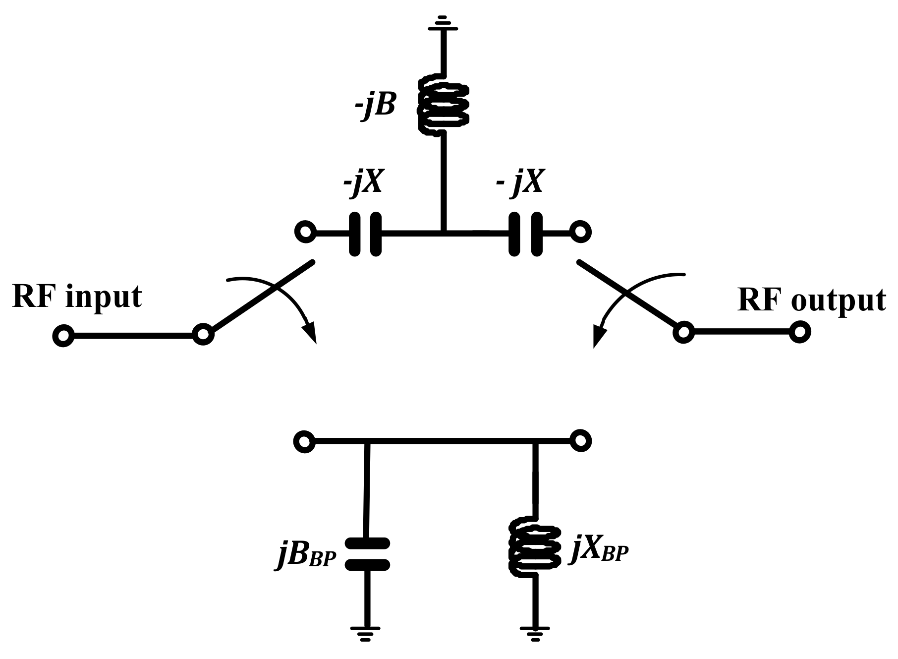
Figure 4 shows the high/bandpass phase shifter. To improve the insertion loss, a bandpass topology is used instead of a low-pass topology. The bandpass topology is a shunt connection by the inductor and capacitor in parallel at the center frequency to prevent the leaking of the RF signal to the ground. The signal is passed from the input to the output without an inductor. Ideally, the insertion loss and phase of the bandpass topology are zero. The phase shift Δϕ of the high-/bandpass network is:
Δ ϕ = t a n 1 B X 2 2 X B 2 1 B X .
Note that this is half of the phase shift of the high-/low-pass network. Therefore, for a matched lossless situation, B and X can be determined to be [18]:
X = tan Δ ϕ 2 ,
B = sin Δ ϕ .
Two high-pass/bandpass networks are used for the 45° and 90° phase bits, respectively, to have less losses than that of the low-pass topology.

2.3. Transmission Line with Traveling Wave Switch and Capacitive Loaded Phase Shifter

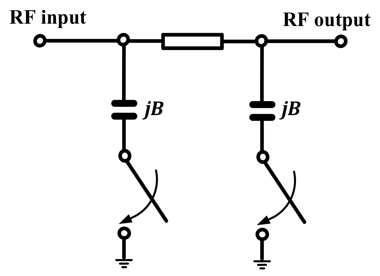
Figure 5 shows the schematic diagram of a transmission line with a traveling wave switch and capacitive loaded network. The loaded-line phase shifter is often used at lower than 45 degrees to provide a low loss and compact size. The capacitive load provides a perturbation in the phase of the signal when the transistor turns on and exhibits a small effect on the amplitude of the signal. A phase shifter with lower losses is obtained by the capacitive load because of the high reflection coefficient. A quarter wavelength transmission line is used to minimize the amplitude perturbation for the on- and off-states. The cascaded connection of the transmission line with a traveling wave switch and capacitive loaded networks provides the desired phase shift. According to the ABCD matrices, a transmission line with traveling wave switch and capacitive loaded networks can be written as [22]:
A B C D = 1 0 j B 1 × 0 j j 0 × 1 0 j B 1 = B j j 1 B 2 B ,
where B is the shunt susceptance of the capacitor in Figure 2. The insertion loss can be obtained by:
S 21 = 2 2 B + j ( 2 B 2 ) .
The phase caused by the switching transmission line is:
ϕ = t a n 1 1 B B 2 .
Two transmission lines with traveling wave switch and capacitive loaded networks are used for the 11.25° and 22.5° phase bit, respectively, to obtain a low loss and a compact size.

2.4. Design of 5-Bit X-Band Phase Shifter

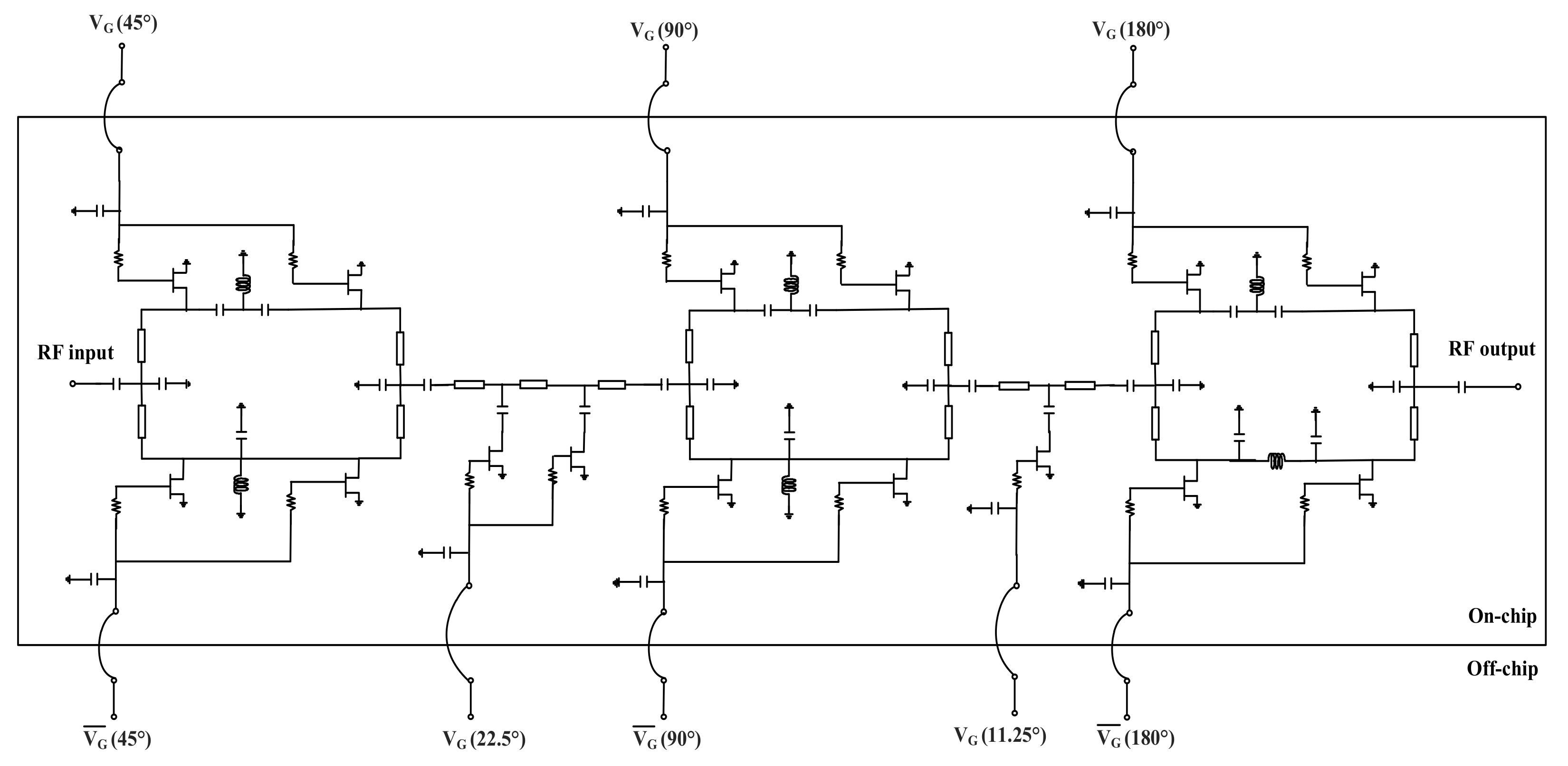
The topologies used in the 180° phase bits, 45° and 90° phase bits, and 11.25° and 22.5° phase bits are the high-pass/low-pass network, high-pass/bandpass network, and the transmission line with traveling wave switch and capacitive loaded network, respectively. The optimal bits are ordered in a 45°–22.5°–90°–11.25°–180° arrangement to obtain a best match and property isolation between each bit. The transistor acts as a switch that selects the controlled signal path depending on the gate bias (VG). Phase shifters are selected when the gate bias is −5 V (transistor is turn off). The phase does not change when the transistor is turned on (VG = 0 V). Table 1 shows the truth table of the five major bits, while Figure 6 shows the complete schematic diagram of the of 5-bit X-band phase shifter.

3. Results and Discussion

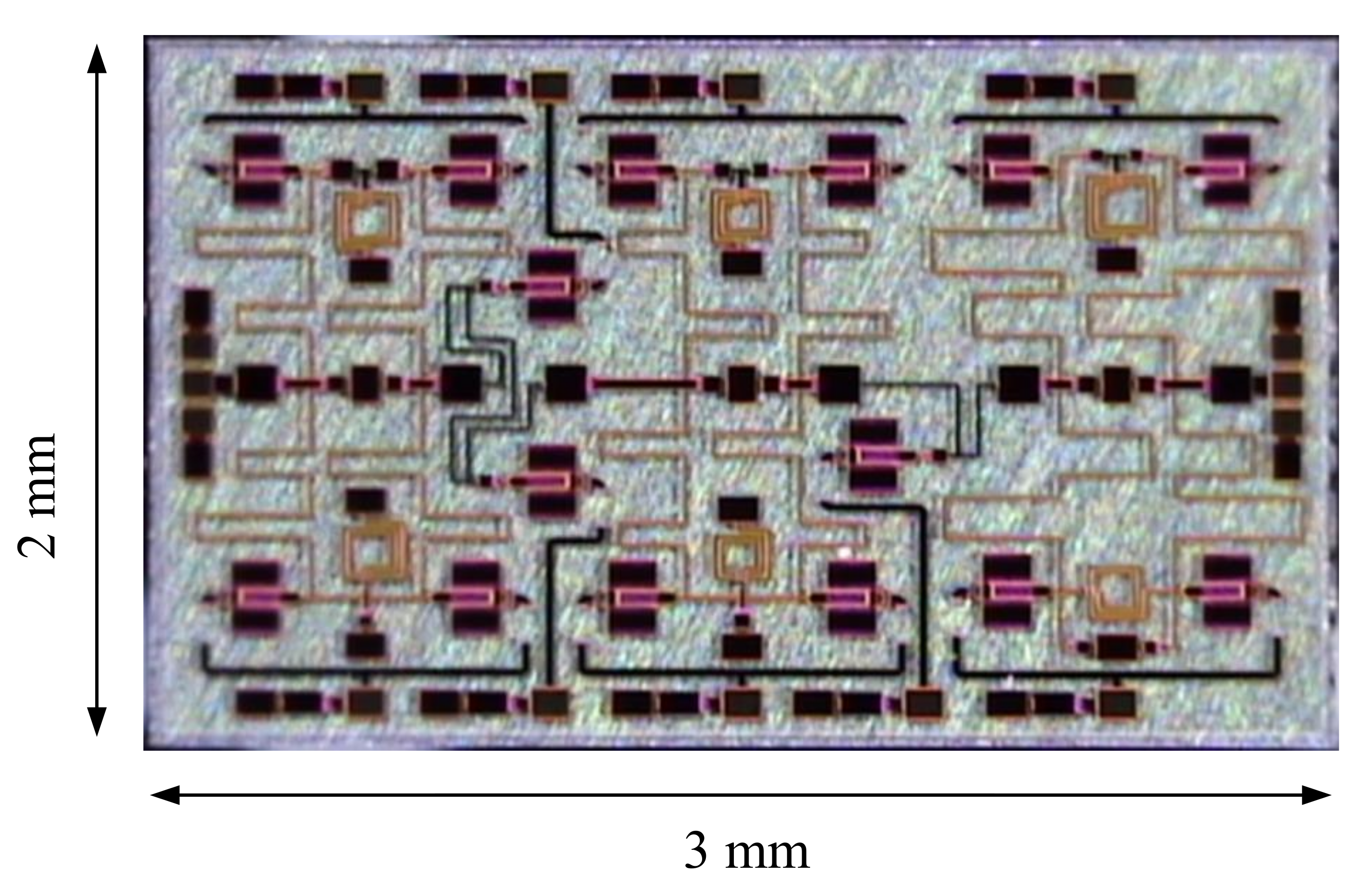
In this work, the width of all transistors from WIN Semiconductors Corp. was 2 × 125 μm based on a 0.25 μm AlGaN/GaN HEMT on a SiC substrate. The unity current gain cutoff frequency (ft) and maximum oscillation frequency (fmax) of the GaN HEMT at a drain voltage of 28 V are 24.5 and 75 GHz, respectively. The MMIC uses an air bridge to the cross-metal layers for balanced signals. The backside of the substrate is shielded using Aurum. The via-holes inside every source pad was connected to the backside for ground connection to release thermal dissipation. The 5-bit X-band GaN HEMT phase shifter was simulated using the Advance Design System (ADS) software. To obtain a large phase shift, five phase shifters were cascade-connected and fabricated into one chip. Electromagnetic simulation is needed to consider the result of the interfering signals for circuit design to optimize the performance of the 5-bit X-band GaN HEMT phase shifter. Figure 7 shows a photograph of the fabricated 5-bit X-band phase shifter MMIC. The chip area including all pads of the phase shifter is 2 × 3 mm2.
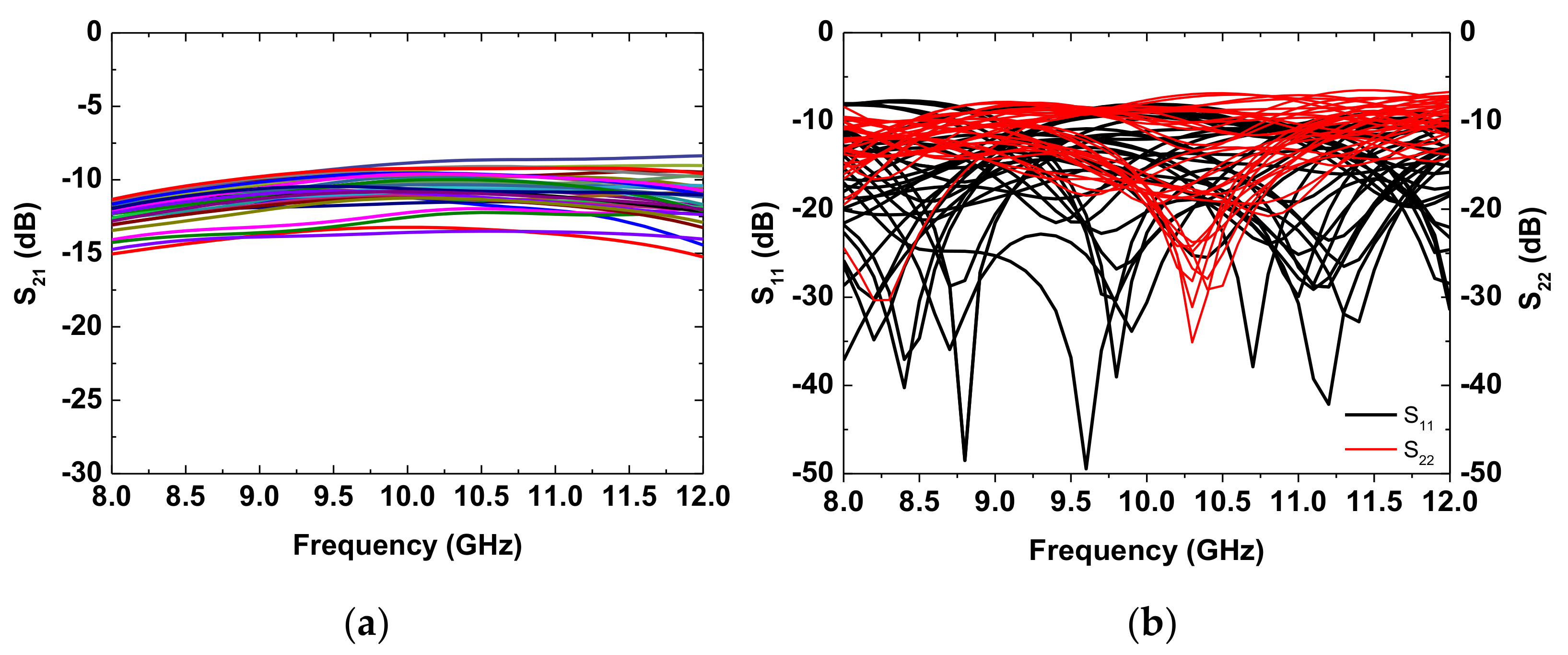
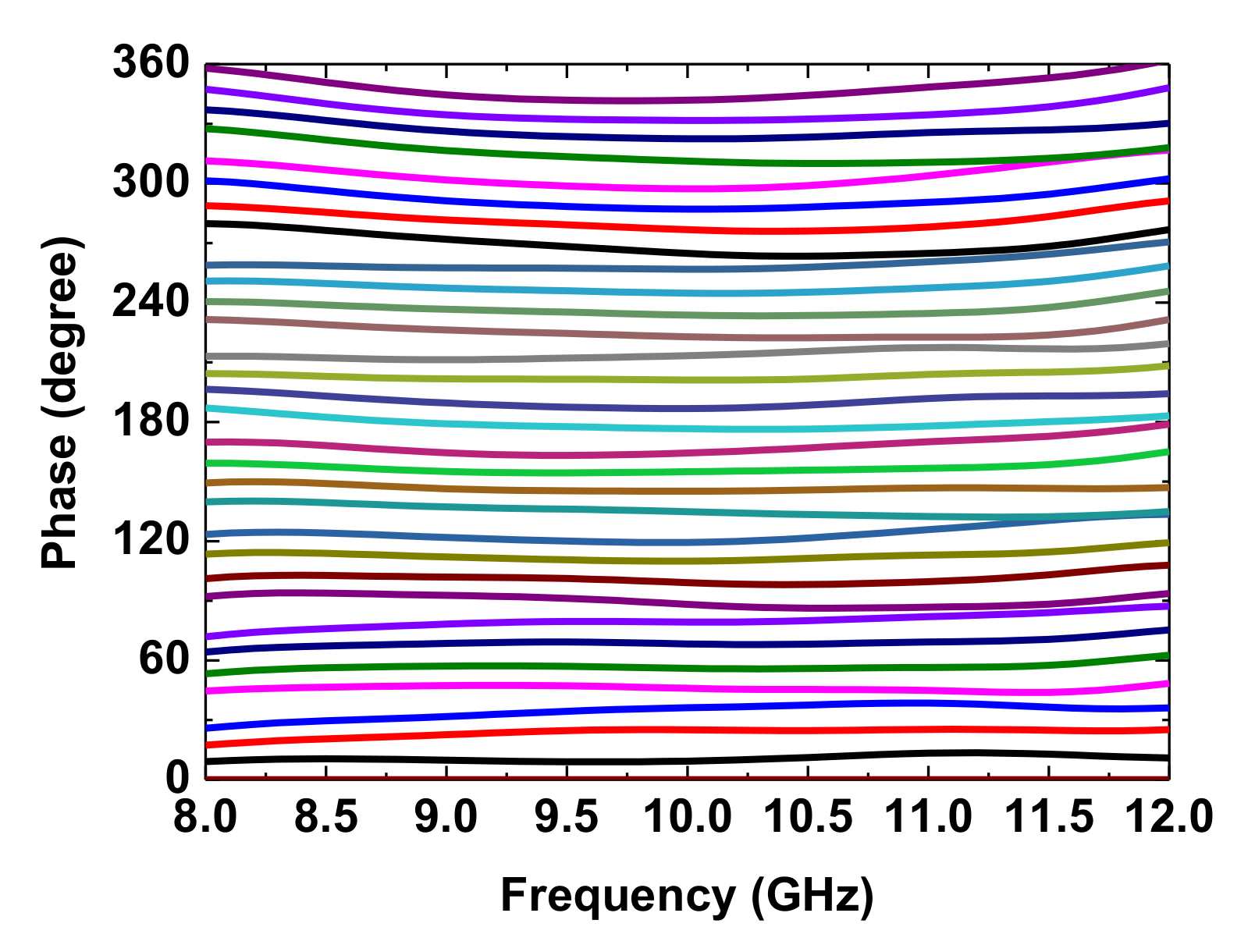
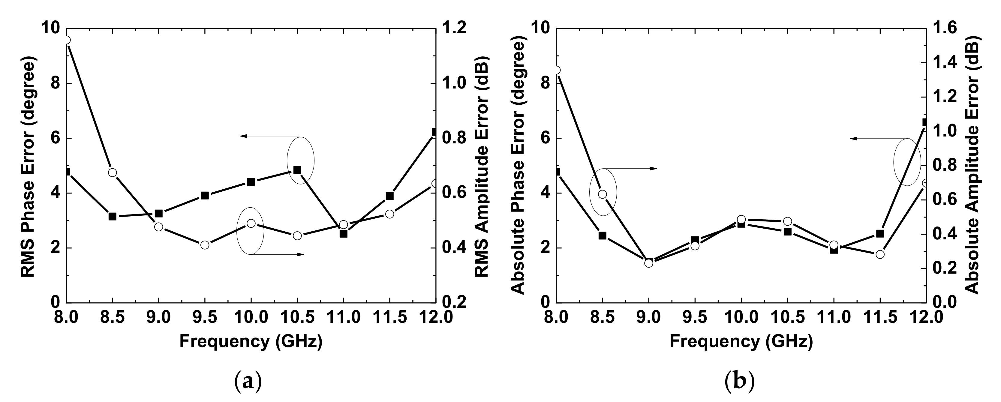
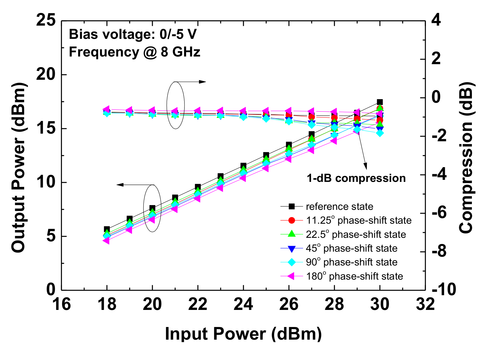
The fabricated phase shifter on the wafer was measured using the Agilent E8364C Vector Network Analyzer and switch gate biases of 0 V and −5 V to obtain the small-signal performance. Figure 8 shows the measured insertion loss and return loss of the 5-bit phase shifter. The state-to-state variation in the insertion loss is 11.8 ± 3.45 dB from 8 to 12 GHz and 11.7 ± 3.26 dB from 8 to 11.5 GHz. The input and output return losses are more than 8 dB for all 32 states over 8-12 GHz. Figure 9 shows the measured phase response of the phase shifter for all 32 states over 8–12 GHz. The RMS and absolute phase errors and amplitude errors in the 8–12 GHz bandwidth are depicted in Figure 10. An RMS phase error less than 6.23° and an RMS amplitude error less than 1.15 dB over the 8–12 GHz bandwidth were obtained. The phase shifter achieves a low RMS phase error of 2.52° at 11 GHz and a low RMS amplitude error of 0.41 dB at 9.5 GHz. Over 8–11.5 GHz, an RMS phase error of less than 4.84° and an RMS amplitude error of less than 0.67 dB were achieved that were 1.39° and 0.48 dB lower than those at 8–12 GHz. The absolute phase error and absolute amplitude are less than 6.58° and 1.35 dB at 8–12 GHz, respectively, which is slightly higher than the RMS errors. A summary of the measurement results is given in Table 2. To study the power-handing capability of the phase shifter, the continuous wave P1dB power-handling capability was obtained under a gate bias of 0/−5 V, as shown in Figure 11. The P1dB power-handing capability of the five primary phase shift states is larger than 29 dBm at 8 GHz.
Table 3 summarizes the performances of the proposed phase shifter and other reported [7,10,13,23] for comparison. As expected, GaN technology provides better insertion loss, RMS phase error, and RMS amplitude error for phase shifters than CMOS and GaAs technologies [7,10,23]. Our design possesses the lowest 2.52° RMS phase error at 11 GHz. Moreover, the RMS phase error is 2.52–6.23 °, which is 0.6–1° lower than that previously published over 8–11.5 GHz [13]. This is because transmission line by traveling wave switch and capacitive load concept provides an accurate phase for the 11.25° and 22.5° phase bit to achieve a low RMS phase error. GaN-based phase shifters demonstrate low insertion loss, low RMS phase and amplitude errors, and high power processing capabilities, which can be used in single-chip transmitter/receiver modules for wideband applications.
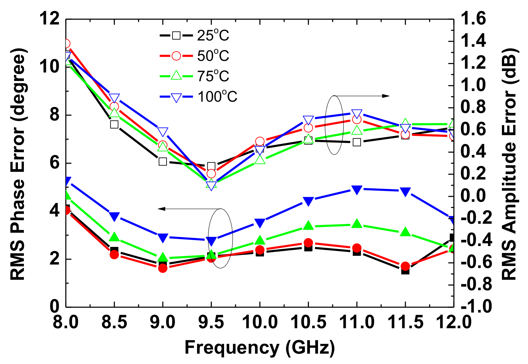
To verify the temperature effect, five primary phase shift states were measured from 25 to 100 °C. Figure 12 shows the RMS phase error and RMS amplitude error of the five primary phase shift states from 25 to 100 °C. The difference in the RMS values obtained in Figure 9 and Figure 11 is due to the difference in the number of states calculated, which are 32 and 5, respectively. The RMS phase error and RMS amplitude error at 8–12 GHz were less than 5.3° and 1.27 dB, respectively, at 100 °C. The maximum increases in the RMS phase error and RMS amplitude error were 3.3° and 0.27 dB at 100 °C, respectively. The slight increase in the RMS phase error and RMS amplitude error with increased temperature is due to the increase in the permittivity and loss tangent of the silicon carbon materials [24]. Therefore, the temperature effect on the phase shifter should be carefully considered in high-power applications.

4. Conclusions

A phase shifter based on a high-pass/low-pass network, two high-pass/bandpass networks, and two transmission lines based on traveling wave switch and capacitive load networks was successfully implemented. The design of the phase shifter was described. The fabricated phase shifter showed an insertion loss of below 15.1 dB and an input/output return loss of better than 8.5 dB. The RMS phase error and RMS amplitude error are 6.23° and 1.15 dB, respectively, over a frequency range of 8–12 GHz. The power handling capability of the circuit was better than 29 dBm at 8 GHz. A slight increase in the RMS phase error and RMS amplitude error were observed from 25 °C to 100 °C because of the change in the physical characteristics of the SiC substrate. The measurement results demonstrated the wide band, good phase shifting performance, and high-power handling capability of the phase shifter, which are useful for wideband phased-array applications.

Author Contributions

Conceptualization, H.-L.K. and H.-C.C.; methodology, H.-L.K. and C.-M.C.; validation, H.-C.C. and C.-M.C.; resources, H.-L.K. and C.-M.C.; writing—original draft preparation, H.-L.K.; writing—review and editing, H.-C.C., L.-C.C., and C.-M.C.; funding acquisition, H.-L.K. and H.-C.C. All authors have read and agreed to the published version of the manuscript.

Funding

This work was supported by the Ministry of Science and Technology, Taiwan (no. 109-2221-E-182-027 and no. 109-2622-E-182-001-CC2) and the Chang Gung Memorial Hospital, Taiwan (BMRP957 and CMRPD2K0042).

Data Availability Statement

The data presented in this study are available in article.

Acknowledgments

The authors thank the Centre for Reliability Sciences and Technologies at Chang Gung University for their help. This work was partially supported by the Ministry of Science and Technology, Taiwan (no. 109-2221-E-182-027 & no. 109-2622-E-182-001-CC2), and the Chang Gung Memorial Hospital, Taiwan (BMRP957 & CMRPD2K0042).

Conflicts of Interest

The authors declare no conflict of interest.

References

  1. Bai, C.X.; Cheng, Y.J.; Ding, Y.R.; Zhang, J.F. A Metamaterial-Based S/X-Band Shared-Aperture Phased-Array Antenna With Wide Beam Scanning Coverage. IEEE Trans. Antennas Propag. 2020, 68, 4283–4292. [Google Scholar] [CrossRef]
  2. Wang, Z.; Pan, X.; Yang, F.; Xu, S.; Li, M. Real-Time Mode Switching and Beam Scanning of High-Gain OAM Waves Using a 1-Bit Reconfigurable Reflectarray Antenna. Electronics 2020, 9, 2181. [Google Scholar] [CrossRef]
  3. Guoming, L.; Sabirova, F.M.; Morozov, A.V. Simulation and experimental measurement of digital multi-beamforming phased antenna array in the frequency range C. Results Phys. 2019, 13, 102310. [Google Scholar] [CrossRef]
  4. Wang, L.; You, Y.; Mikul, A.; Bonebright, R.; Kromholtz, G.; Heo, D.; Sun, P. Highly Linear Ku -Band SiGe PIN Diode Phase Shifter in Standard SiGe BiCMOS Process. IEEE Microw. Wirel. Compon. Lett. 2009, 20, 37–39. [Google Scholar] [CrossRef]
  5. Kim, T.T.; Feng, J.; Shehab, S.H.; Karmakar, N.C. 1.4 GHz Low-Cost PIN Diode Phase Shifter for L -Band Radiometer Antenna. IEEE Access 2019, 7, 2181. [Google Scholar]
  6. Moshaev, V.; Leibin, Y.; Malka, D. Optimizations of Si PIN diode phase-shifter for controlling MZM quadrature bias point using SOI rib waveguide technology. Opt. Laser Technol. 2021, 138, 106844. [Google Scholar] [CrossRef]
  7. Kang, D.-W.; Lee, H.D.; Kim, C.-H.; Hong, S. Ku-band MMIC phase shifter using a parallel resonator with 0.18-/spl mu/m CMOS technology. IEEE Trans. Microw. Theory Tech. 2006, 54, 294–301. [Google Scholar] [CrossRef]
  8. Sim, S.; Jeon, L.; Kim, J.-G. A Compact X-Band Bi-Directional Phased-Array T/R Chipset in 0.13 muhboxm CMOS Technology. IEEE Trans. Microw. Theory Tech. 2013, 61, 562–569. [Google Scholar] [CrossRef]
  9. Lee, H.; Kim, Y.; Lee, I.; Kim, D.; Park, K.; Jeon, S. A Ku-Band GaAs Multifunction Transmitter and Receiver Chipset. Electronics 2020, 9, 1327. [Google Scholar] [CrossRef]
  10. Tsai, J.-H.; Kuo, Y.-T.; Yu, H.-C. A Ku-Band 3-Bit Phase Shifter MMIC using GaAs pHEMT Technology for Phased Array System. Microw. Opt. Technol. Lett. 2014, 57, 771–774. [Google Scholar] [CrossRef]
  11. Hettak, K.; Ross, T.K.; Gratton, D.; Wight, J. A New Type of GaN HEMT Based High Power High-Pass/Low-Pass Phase Shifter at X Band. In Proceedings of the IEEE MTT-S International Microwave Symposium, Montreal, QC, Canada, 17–22 June 2012. [Google Scholar]
  12. Ross, T.N.; Cormier, G.; Hettak, K.; Wight, J.S. High-Power X-Band GaN Switched-Filter Phase Shifter. In Proceedings of the IEEE MTT-S International Microwave Symposium, Tampa, FL, USA, 1–6 June 2014. [Google Scholar]
  13. Sun, P.; Liu, H.; Zhang, Z.; Geng, M.; Zhang, R.; Luo, W. X-band 5-bit MMIC phase shifter with GaN HEMT technology. Solid-state Electron. 2017, 136, 18–23. [Google Scholar] [CrossRef]
  14. Kingsley, N.; Papapolymerou, J. Organic “Wafer-Scale” packaged miniature 4-bit RF MEMS phase shifter. IEEE Trans. Microw. Theory Tech. 2006, 54, 1229–1236. [Google Scholar] [CrossRef]
  15. Malczewski, A.; Eshelman, S.; Pillans, B.; Ehmke, J.; Goldsmith, C.L. X-band RF MEMS phase shifters for phased array applications. IEEE Microw. Guided Wave Lett. 1999, 9, 517–519. [Google Scholar] [CrossRef]
  16. Atwater, H. Circuit Design of the Loaded-Line Phase Shifter. IEEE Trans. Microw. Theory Tech. 1985, 33, 626–634. [Google Scholar] [CrossRef] [Green Version]
  17. Garver, R. Broad-Band Diode Phase Shifters. IEEE Trans. Microw. Theory Tech. 1972, 20, 314–323. [Google Scholar] [CrossRef]
  18. Wang, Z.; Pan, X.; Yang, F.; Xu, S.; Li, M. A New Type of Robust Broadband, GaN HEMT-Based High Power High-pass/Low-pass 22.5° Phase Shifter. Microw. Opt. Technol. Lett. 2014, 56, 347–349. [Google Scholar]
  19. Zhou, S.; Zhou, S.; Zhang, J.; Wu, J.; Yang, H.; Wang, Z. A 7.5–9 GHz GaAs Two-Channel Multi-Function Chip. Electronics 2019, 8, 395. [Google Scholar] [CrossRef] [Green Version]
  20. Florian, C.; Gibiino, G.P.; Santarelli, A. Characterization and Modeling of RF GaN Switches Accounting for Trap-Induced Degradation Under Operating Regimes. IEEE Trans. Microw. Theory Tech. 2018, 66, 5491–5500. [Google Scholar] [CrossRef]
  21. Hong, J.-S.; Lancaster, M.J. Microstrip Filters for RF/Microwave Applications; JohnWiley and Sons: Hoboken, NJ, USA, 2004; Volume 167. [Google Scholar]
  22. Lin, K.-Y.; Tu, W.-H.; Chen, P.-Y.; Chang, H.-Y.; Wang, H.; Wu, R.-B. Millimeter-Wave MMIC Passive HEMT Switches Using Traveling-Wave Concept. IEEE Trans. Microw. Theory Tech. 2004, 52, 1798–1808. [Google Scholar] [CrossRef]
  23. Alsuraisry, H.; Cheng, J.-H.; Wang, H.-W.; Zhong, J.-Y.; Tsai, J.-H.; Huang, T.-W. A X-band digitally controlled 5-bit phase shifter in 0.18-μm CMOS technology. In Proceedings of the 2015 Asia-Pacific Microwave Conference (APMC), Nanjing, China, 6–9 December 2015; Volume 2, pp. 1–3. [Google Scholar] [CrossRef]
  24. Yang, H.-J.; Yuan, J.; Li, Y.; Hou, Z.-L.; Jin, H.-B.; Fang, X.-Y.; Cao, M.-S. Silicon carbide powders: Temperature-dependent dielectric properties and enhanced microwave absorption at gigahertz range. Solid State Commun. 2013, 163, 1–6. [Google Scholar] [CrossRef]
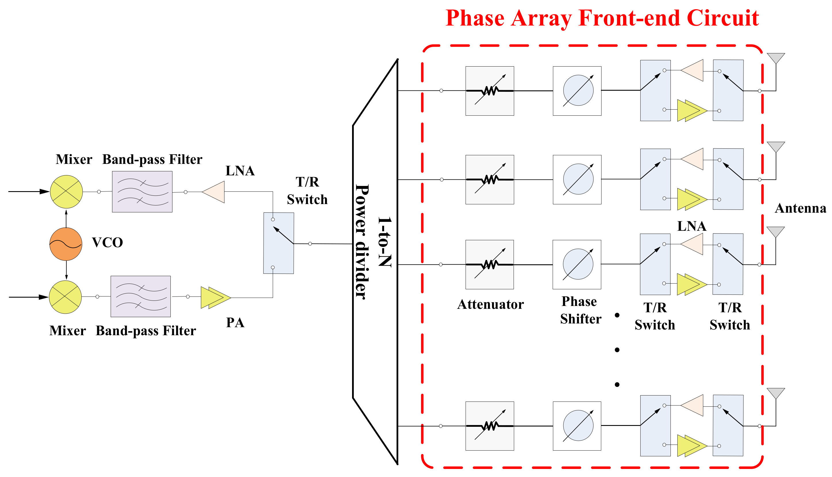
Figure 1. Schematic of radio frequency (RF) beamforming.
Electronics 10 00658 g001
Figure 2. Schematic of the high-pass/low-pass phase shifter.
Electronics 10 00658 g002
Figure 3. (a) Schematic of the shunt single-pole/double-throw (SPDT) switch; (b) simulated insertion loss, isolation, and phase shift between on and off states of the shunt SPDT switch.
Electronics 10 00658 g003
Figure 4. Schematic of the high-pass/band-pass phase shifter.
Electronics 10 00658 g004
Figure 5. Schematic of transmission line with traveling wave switch and capacitive loaded phase shifter.
Electronics 10 00658 g005
Figure 6. Complete schematic of the 5-bit X-band phase shifter.
Electronics 10 00658 g006
Figure 7. Photograph of the 5-bit gallium nitride (GaN) monolithic microwave integrated circuit (MMIC) phase shifter.
Electronics 10 00658 g007
Figure 8. Measured (a) insertion loss and (b) input/output return loss of all 32 states of the phase shifter.
Electronics 10 00658 g008
Figure 9. Measured relative phase of the phase shifter for all 32 states.
Electronics 10 00658 g009
Figure 10. (a) RMS phase error and RMS amplitude error; (b) absolute phase error and absolute amplitude error of the 32 states of phase shifter.
Electronics 10 00658 g010
Figure 11. Measured power handing of the phase shifter.
Electronics 10 00658 g011
Figure 12. Temperature effect of the rms phase error and rms amplitude error of the five primary states of phase-shift at 25–100 °C.
Electronics 10 00658 g012
Table 1. Truth table of 5-bit X-band phase shifter.
VG45°22.5°90°11.25°180°
11.25°0 (off)00−50
22.5°0−5000
45°−5 (on)0000
90°00−500
180°0000−5
Table 2. Measurement results for the 5-bit phase shifter.
Frequency (GHz)8–128–11.59.511
Insertion loss (dB)11.8 ± 3.4511.7 ± 3.2611.5 ± 2.2411.2 ± 2.54
Return loss (dB)>8>8>8>8
RMS phase error (deg.)<6.23<4.843.912.52
Absolute phase error (deg.)<6.58<4.772.281.93
RMS amplitude error (dB)<1.15<0.670.410.49
Absolute amplitude error (dB)<1.35<1.350.330.34
Table 3. Comparison of monolithic microwave integrated circuit MMIC phase shifters.
Ref.[7][10][13][23]This Work
Process0.18 μm CMOS0.15 μm pHEMT0.25 μm GaN HEMT0.18 μm CMOS0.25 μm GaN HEMT
Bandwidth (GHz)9–1510–148–12
(8–11.5)
8–12
(8–11.5)
8–12
(8–11.5)
Phase resolution (bit)53555
Insertion loss (dB)15.5 ± 3.56.5 ± 1.59.95 ± 2.0514 ± 311.65 ± 3.45
Return loss (dB)878.588
RMS phase error (deg.)6.19–12.22.22–15.363.67–5.64
(3.66–5.63)
7.24–9.16
(7.55–9.16)
2.52–6.23
(2.52–4.84)
RMS amplitude error (dB)0.25–2.120.25–1.110.38–0.77
(0.37–0.77)
0.43–1.25
(0.43–1.17)
0.41–1.16
(0.41–1.16)
P1dB power handing (dBm)- 32- 29
Size (mm2)3.411.58.550.816
Publisher’s Note: MDPI stays neutral with regard to jurisdictional claims in published maps and institutional affiliations.