Article

Investigation on a 220 GHz Quasi-Optical Antenna for Wireless Power Transmission

1
School of Electronic Science and Engineering, University of Electronic Science and Technology, Chengdu 610054, China
2
Terahertz Science and Technology Key Laboratory of Sichuan Province, University of Electronic Science and Technology of China, Chengdu 610054, China
3
School of Physics, University of Electronic Science and Technology of China, Chengdu 610054, China
4
Department of Electrical and Electronics Engineering, Ariel University, Ariel 40700, Israel
*
Author to whom correspondence should be addressed.
Electronics 2021, 10(5), 634; https://doi.org/10.3390/electronics10050634
Submission received: 30 January 2021 / Revised: 3 March 2021 / Accepted: 5 March 2021 / Published: 9 March 2021

Abstract

:
This paper investigates a 220 GHz quasi-optical antenna for millimeter-wave wireless power transmission. The quasi-optical antenna consists of an offset dual reflector, and fed by a Gaussian beam that is based on the output characteristics of a high-power millimeter-wave radiation source-gyrotron. The design parameter is carried on by a numerical code based on geometric optics and vector diffraction theory. To realize long-distance wireless energy transmission, the divergence angle of the output beam must be reduced. Electromagnetic simulation results show that the divergence angle of the output beam of the 5.6 mm Gaussian feed source has been significantly reduced by the designed quasi-optical antenna. The far-field divergence angle of the quasi-optical antenna in the E plane and H plane is 1.0596° and 1.0639°, respectively. The Gaussian scalar purity in the farthest observation field (x = 1000 m) is 99.86%. Thus, the quasi-optical antenna can transmit a Gaussian beam over long-distance and could be used for millimeter-wave wireless power transmission.

1. Introduction

Microwave power transmission (MPT), as a feasible solution for long-distance wireless power transmission, has attracted much attention for many potential applications, such as space solar power generation [1,2], continuous high-altitude relay platforms [3,4], etc. Compared to microwaves, millimeter waves have higher frequencies and better beam directivity [5], which are considered more conducive to long-distance wireless energy transmission applications. However, due to the lack of high efficiency and high power millimeter-wave source (such as magnetron in the microwave region), the investigations on millimeter-wave power transmission are limited.
In recent decades, the high power millimeter-wave source has achieved rapid development [6,7,8]. Gyrotron, which is also named electron–cyclotron maser, is based on stimulated cyclotron emission processes involving energetic electrons in gyrational motion [9,10,11]. Unlike the traditional vacuum electronic devices utilizing slow-wave circuits as their interaction structures, gyrotron is a fast-wave device that has much larger physical dimensions than the operating wavelength. Therefore, it has higher output power and higher efficiency than traditional vacuum electronics devices in the millimeter-wave region [12,13]. Until now, a 2.2-MW peak power with an efficiency of 48% has been obtained in 170-GHz gyrotron in Forschungszentrum Karlsruhe, and a 70% peak efficiency with power 0.8-MW has been achieved in 70-GHz gyrotron in the Russian Academy of Science [14]. Thus, the millimeter-wave power transmission based on gyrotron becomes practicable.
However, the divergence angle of the beam output by the gyrotron is large, which makes the energy collapse sharply when it travels a long distance. Therefore, the Gaussian beam output by the gyrotron is mainly applied for short distances [15,16,17]. Accordingly, to make it suitable for long-distance energy transmission, it is necessary to solve the problem of the large divergence angle of the gyrotron output Gaussian beam. There are still few investigations directly devoted to studying this issue, as far as the author knows, but some similar research work inspire associating. For example, the Gaussian laser beam is different from the Gaussian beam output by the gyrotron in the frequency band. In the application of semiconductor lasers, it has been presented that a collimating lens can be used to increase the waist radius of the Gaussian laser beam, thereby reducing the divergence angle of the Gaussian laser beam [18]. Nevertheless, for a gyrotron with high frequency and high output power, the material and manufacturing process of the required lens are difficult to achieve. In addition, some scholars have proposed a feed-forward Cassegrain geometry to increase the waist radius of the Gaussian laser beam, thereby reducing the divergence angle of the Gaussian laser beam [19]. However, the Gaussian beam obtained by this structure is greatly influenced by the aperture blockage. The center of the gotten beam is empty, and its Gaussian content is not suitable for energy transmission.
Based on the above, this paper proposes an offset Cassegrain dual reflector scheme, which uses 220 GHz gyrotron output Gaussian beam as the feed source to form together with a quasi-optical antenna structure. This design structure can reduce the divergence angle of the Gaussian beam output by the gyrotron, thereby realizing the wireless energy transmission over a long distance in the millimeter-wave band. Meanwhile, 220 GHz is selected as the operating frequency, which is the highest atmospheric window with low transmission attenuation in the millimeter-wave region [5].
The quasi-optical antenna structure and physical principle of reducing the divergence angle of the Gaussian beam output by the gyrotron will be addressed in Section 2, where a numerical calculation program for optimizing the quasi-optical antenna parameters is designed. Simulation results and discussion about the quasi-optical antenna on wireless energy transmission are presented in Section 3, followed by the conclusion in Section 4.

2. Structure and Design Principles

2.1. Antenna Structure

The 3D structure of the proposed quasi-optical antenna is described in Figure 1. And a standard fundamental mode Gaussian feed is considered to be a substitute for the Gaussian beam output by the 220 GHz gyrotron. The dual reflector antenna is composed of a main-reflector and a subreflector. To prevent the feed source and the subreflector from blocking the reflected wave, the offset Cassegrain dual reflector scheme [20,21] is adopted here. The feed source and the subreflector are offset from the main reflector.

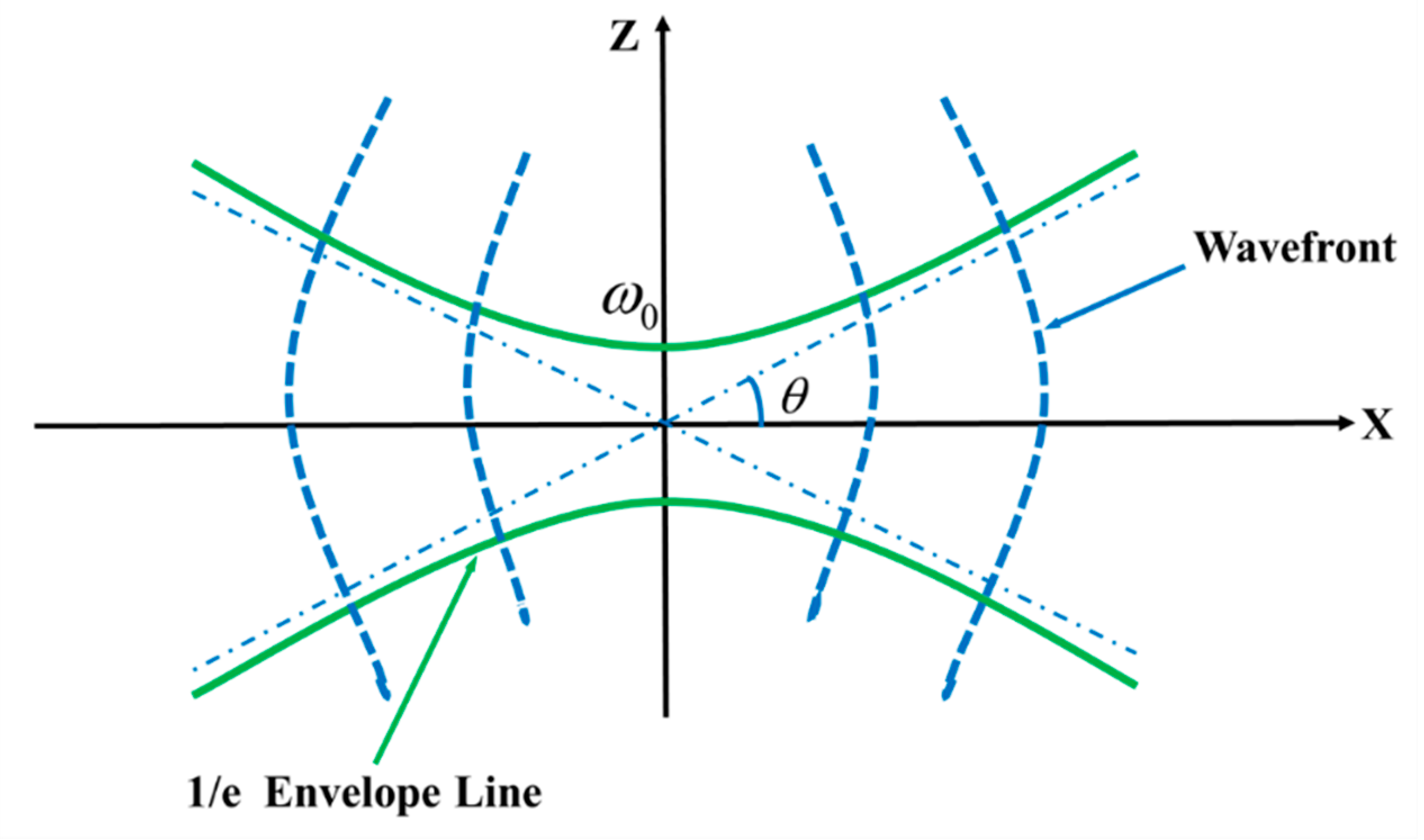
2.2. Gaussian Beam Propagation Theory

During the propagation of the Gaussian beam, most of the energy is concentrated near the propagation axis. The wave amplitude in the transverse direction is variable and conforms to the Gaussian distribution. Considering the paraxial approximation condition, the field distribution of a fundamental Gaussian beam propagating along the X-direction can be assumed as [22] (pp. 15–16):
φ ( r , x ) = u ( r , x ) exp ( j k x ) = 2 π ω 2 ( x ) × exp ( r 2 ω 2 ( x ) ) × exp ( j [ k ( x + r 2 2 R ( x ) ) ] ϕ )
ω ( x ) = ω 0 1 + ( λ x π ω 0 2 ) 2
R ( x ) = x [ 1 + ( π ω 0 2 λ x ) 2 ]
where r is the radial distance from the point to the propagation axis X. ω ( x ) is defined as the beam radius of the position where the amplitude decreases to 1/e; At x = 0, the beam radius of the Gaussian beam is the smallest, expressed by ω0, which is also defined as Gaussian beam waist. The wavenumber is k = 2 π / λ . R(x) is a measure of the radius of curvature of the wavefront. λ is the wavelength.
It is noteworthy that the Gaussian beam’s main mode is an approximate solution under the paraxial condition of the wave equation. Whether this paraxial approximation is effective depends on the electrical size of the Gaussian beam waist. The requirements are as follows [22] (pp. 35–36):
ω 0 / λ 0.9003
As long as the waist of a Gaussian beam satisfies the above equation, its Gaussian beam propagation characteristics can be guaranteed, and various related formulas can be applied.
Figure 2 shows the propagation of the Gaussian beam and the variation of the beam radius and curvature radius along the propagation direction in the longitudinal section. When the Gaussian beam is far away from the beam waist, the angle between the position where the radius of the Gaussian beam falls to 1/e of the maximum value on the x-axis and the z-axis is defined as the far-field divergence angle (half angle) of the Gaussian beam, as follows:
θ = tan 1 lim x ω ( x ) x = tan 1 λ π ω 0
To realize the long-distance bunching transmission of the Gaussian beam, it is necessary to reduce the divergence angle θ by increasing the Gaussian beam waist ω0. From the perspective of energy, the beam energy contained in the far-field divergence angle accounts for 86.5% [23] of the total energy of the Gaussian beam. Hence, It corresponds to a decrease of 8.68dB in the relative peak power in the far-field pattern.
A Gaussian beam is characterized by the Gaussian mode purity, which is usually described by the correlation coefficient between the output beam E 1 and a theoretical fundamental Gaussian beam E 0 [24]. The correlation coefficient can be defined in two ways: One is the Gaussian scalar content η s , which involves the amplitude of the field. The other is the Gaussian vector content η v , including amplitude and phase, which can be expressed as
η s = S E 1 · E 0 d S S E 1 2 d S · S E 0 2 d S
η v = S E 1 E 0 d S · S E 1 E 0 d S S E 1 2 d S · S E 0 2 d S  
In millimeter-wave wireless power transmission applications, we mainly consider the Gaussian scalar content of different transmission observation surfaces.

2.3. Design of the Reflectors

The geometry of the classical offset Cassegrain dual reflector antenna [20,21] is shown in Figure 3. To simplify the design, this paper adopts three coordinate systems, including the global coordinate system represented as (O, X, Z), the main-reflector coordinate system depicted as (O0, X0, Z0), and the subreflector coordinate system represented as (O1, X1, Z1).
As shown in Figure 3, the main reflector is a rotating parabolic reflector cut by a cone, which can be expressed in (O0, X0, Z0) coordinate system as
x 0 = z 0 2 4 f m ( f m c )       ( z 0 < 0 )
where fm is the focal length of the main reflector, and c is the focal length of the subreflector. It is formed by rotating the above part of the parabolic 360° around the focal point F2. The vertex of the cone and the focal point of the parabolic surface are both F2. The cone angle is θ5.
As illustrated in Figure 4, the subreflector is a rotating hyperboloid surface cut by a cone. The cutting cone of the subreflector is the same as the cutting cone of the main reflector. The cross-section of the second reflecting surface can be expressed in the (O1, X1, Z1) coordinate system as
x 1 2 a 2 ( y 1 2 + z 1 2 ) b 2 = 1       ( x 1 > 0 ) .
It is formed by rotating the right part of the above hyperbola 360° around the focal point F2. The real focus and virtual focus are F1, F2, respectively. The distance from the vertex to the origin O1 is   a and the focal length is c , b = c 2 a 2 .
A fundamental mode Gaussian beam was propagated towards the subreflector and reflected back to the main reflector. According to the geometric optics theory, when the Gaussian ray (emitted from a Gaussian feed source on focus F1) is reflected by the hyperboloid, the reflection line can be regarded as being emitted from the virtual focus F2 of the hyperboloid, which is equivalent to being emitted from the focus F2 of the paraboloid [20]. Therefore, under a certain approximation condition, after being reflected again by the paraboloid, these Gaussian rays can approximately form a beam parallel to the axis of the paraboloid [25]. In other words, the divergent Gaussian beam fed from the focal point F1 can be converted into a plane-like wave—namely, the divergence angle of the Gaussian beam is reduced. Hence, the Gaussian beam can be propagated at a longer distance in free space.
As illustrated in References [20,21], although the dual reflector, shown in Figure 3, can be defined by 21 parameters, only five of them need to be determined for the design, and the other parameters can be derived. However, using only the geometric optics method in [20,21] to obtain the design parameters of the dual reflector is not accurate in the millimeter-wave band. The finite aperture dimension of the dual reflector causes diffraction effects, such as main-reflector spillover, phase error losses, and additional amplitude taper losses [22,26]. Therefore, the vector diffraction theory [27] is applied to accurately verify the performance of the dual reflector.
Based on the vector diffraction theory, the field at any point in free space could be calculated as long as the source field is already known. The observation field radiated from the Gaussian feed can be done by using the Stratton-Chu formula [28].
E ( r ) = S d S { i ω μ [ n × H ( r ) ] g ( r , r ) + [ n · E ( r ) ] g ( r , r ) + [ n × E ( r ) ] × g ( r , r ) }
H ( r ) = S d S { i ω ε [ n × E ( r ) ] g ( r , r ) + [ n · H ( r ) ] g ( r , r ) + [ n × H ( r ) ] × g ( r , r ) }
where E ,   H are the electric and magnetic field vectors on the rectangular aperture. μ is the vacuum permeability, ε is the vacuum permittivity, S′ is the integral aperture surface, n is the unit vector normal to the rectangular aperture surface, and g ( r , r ) is the point source Green’s function, defined by
g ( r , r ) = e j k | r r | / ( 4 π | r r | )
where | r r | is the distance between the observation point and the source point.
The induction current on the reflector is as follows:
J E = 2 ( n × H ) .
The input power P i n   in Gaussian feed is normalized, and the received power P o u t   at the observation plane is
P o u t = 1 2 Re ( E × H ) · n dS
The calculation of the received power P out on the observation surface is based on the main lobe of the beam obtained on the observation surface. The power transmission efficiency   δ t e   from of the Gaussian feed to the observed plane is
δ t e = P out P in
In this paper,   a , c , θ 1 , θ 3   and f m are adopted as the initial parameters for the dual reflector, which is feed by a 220 GHz fundamental Gaussian beam with a waist radius of 5.6 mm. The whole quasi-optical antenna is designed and analyzed for wavelength λ = 1.3636 mm. The initial parameters of the main reflector are f m = 140 λ , c = 55 λ . The parameters of the subreflector are a = 7 λ , θ 1 = 20 , θ 3 = 25 . Although other parameters can be derived from formulas in [20,21], considering the diffraction effects, the vector diffraction theory is applied to accurately verify the parameters of the quasi-optical antenna.
Based on the vector diffraction theory, a numerical simulation Matlab code called Gaussian Optical Mirror Transmission (GOMT) was developed to calculate the field distribution on the mirrors and the observed field, which could adjust and optimize the design parameters of the quasi-optical antenna system. The optimization processing is done by adjusting a , c , θ 1 , θ 3   and f m . The field distribution on different output observed planes is calculated. When Gaussian mode purity reaches a satisfying value, for example, the Gaussian scalar content is over 98%, the optimizing work is ended.
Through optimizing the mirror structure parameters by numerical code GOMT, the optimized design parameters are gotten: The final parameter of the main reflector is f m = 140 λ , c = 57.498 λ . The final parameter of the subreflector is a = 7.002 λ , θ 1 = 20 , θ 3 = 26 . All the final geometrical dimensions, as listed in Table 1, are adjusted by the Matlab code GOMT. The field distribution of the above quasi-optical antenna (ω0 = 5.6 mm) at 220 GHz calculated by GOMT is demonstrated in Figure 5. It shows that the field radiated from the feed is transformed into a well-shaped Gaussian beam at different output observed fields. Moreover, the overall size of the presented quasi-optical antenna is optimized to be 0.135 × 0.134 × 0.210 mm3, which is much smaller than the size of the transmitting antenna based on the microwave transmitting system in Reference [29].
The 3D full-wave simulator Computer Simulation Technology (CST) Microwave Studio has been carried out to verify the GOMT code. The modeling process is as follows: Firstly, setting the center frequency of the whole scheme as f = 220 GHz, we adopt Matlab software to compile a fundamental mode Gaussian beam (ω0 = 5.6 mm) feed radiation model file; Then, following Equations (8) and (9) and parameters in Table 1, we can determine the dual reflector model structure; Finally, the feed radiation file is imported to excite the dual mirror model, and the Asymptomatic Solver is used to simulate the entire quasi-optical antenna structure.
The results are shown in Figure 6. The obtained waist radius are 39.225 mm and 39.62 mm, respectively. And it is obvious to see that the output electric fields in x = 2.2 m calculated by the CST Microwave Studio commercial software are well consistent with the ones calculated by the GOMT code. For further verification, we compared the Gaussian beam correlation coefficients at different positions of the output observed field. The results are shown in Figure 7. It is clear that the scalar purity calculated by the CST Microwave Studio is in accordance with the one calculated by the GOMT code. This GOMT code was previously applied in designing a quasi-optical mode converter for 220 GHz TE03 mode gyrotron, and the experimental results were well consistent with theoretical predictions [30]. The consistency of the CST Microwave Studio commercial software and the GOMT results, as well as the previous experimental verification of the GOMT code, provide solid evidence for the correctness of the GOMT code.
Moreover, compared to the commercial simulation software CST Microwave Studio, the running time is significantly reduced by using the GOMT code. A runtime of seven minutes by GOMT code, compared to more than one day by the 3D full-wave simulation commercial software at the same parameters.

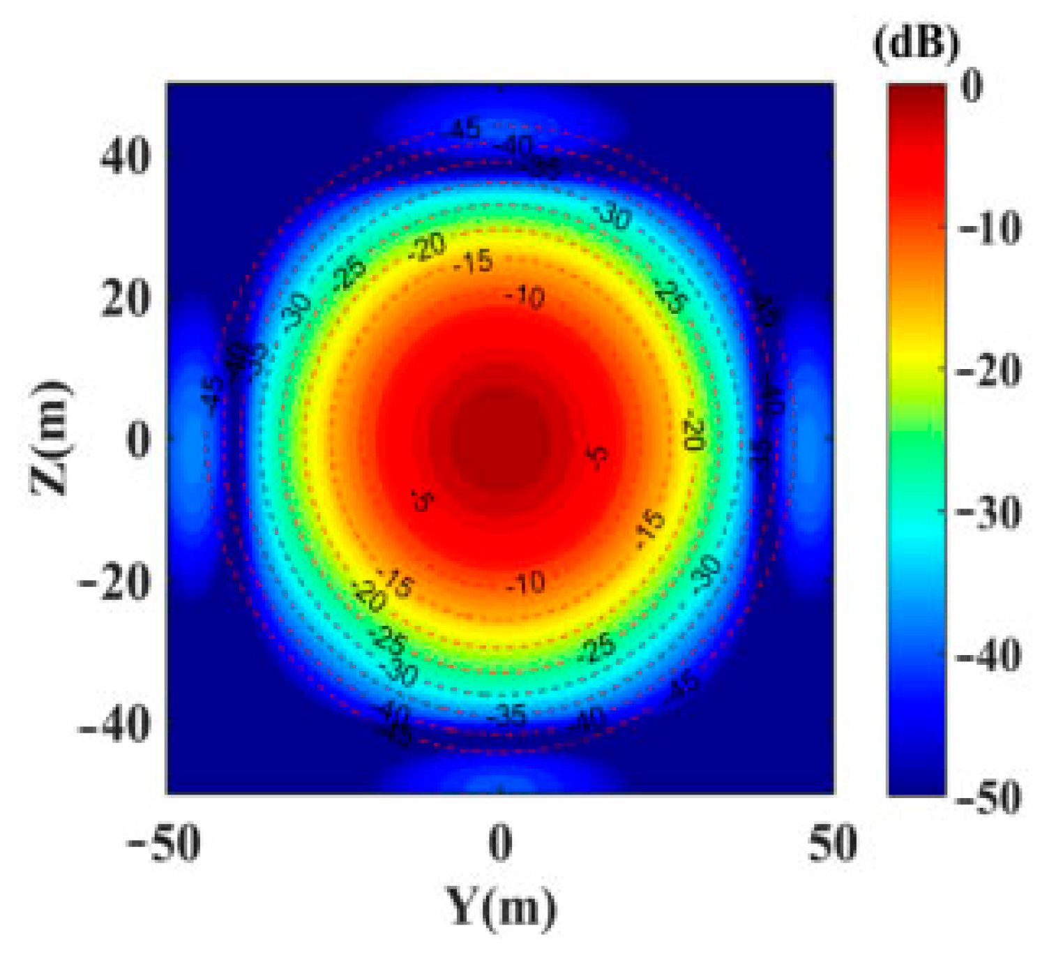
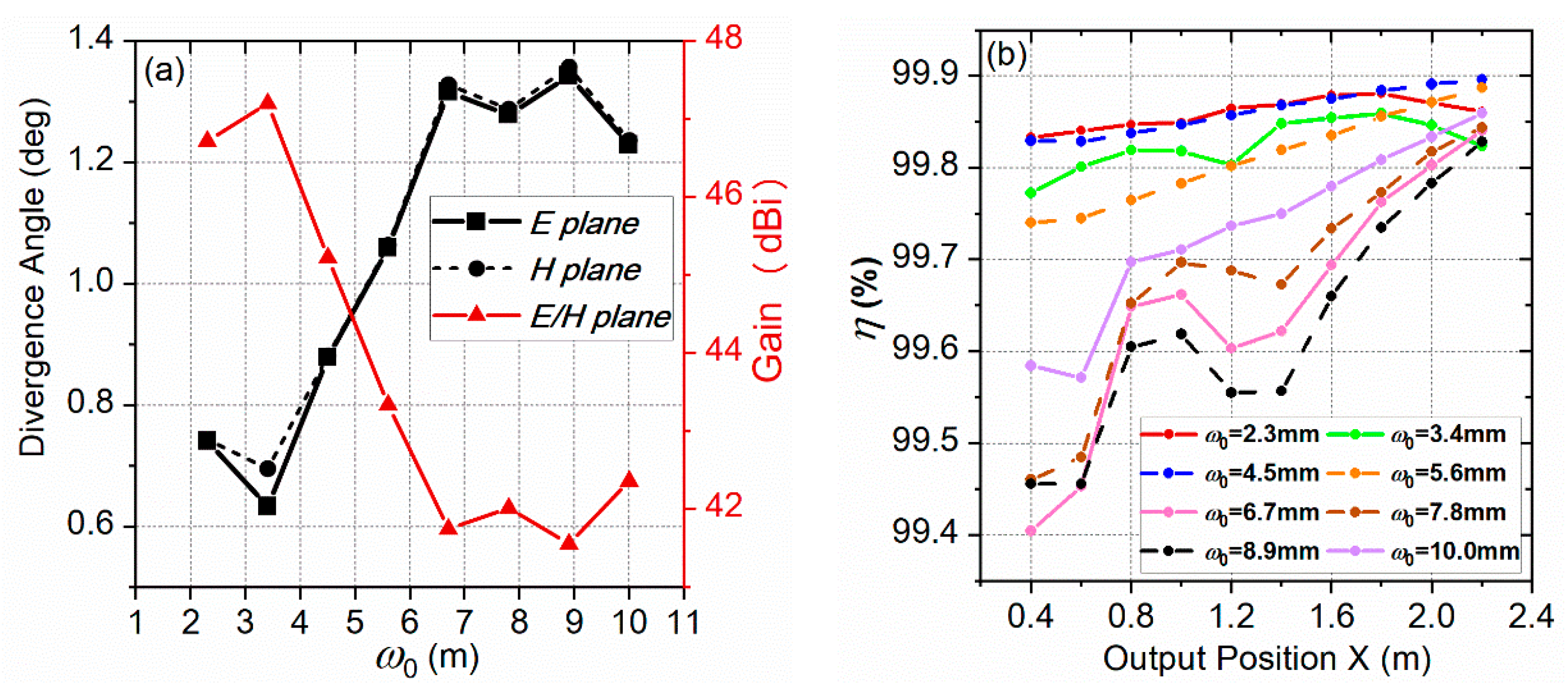
3. Simulation and Discussion

Simulations are initiated by using the 3D full-wave simulator CST Microwave Studio to simulate the reflection and propagation of wave beam through the above designed quasi-optical antenna. The simulation of the cross-section through the quasi-optical antenna in Figure 8b shows the propagation of the energy from the Gaussian feed to the free space on the XZ cross-section. Compared to Figure 8a, the beam radius of the Gaussian beam is significantly reduced; that is, the divergence of the Gaussian beam from the feed source is greatly reduced, which proves the effectiveness of the designed quasi-optical antenna in reducing the Gaussian beam’s divergence.
To further verify the above statements, the far-field radiation patterns of the entire antenna are described in Figure 9. As shown in Table 2, the far-field divergence angle of the 5.6 mm Gaussian feed in E-plane and H-plane is 4.5031° and 4.5032°, respectively. When the dual reflector antenna is added to the 5.6 mm Gaussian feed, the gain of the transmitting system increases from 31.0500 dBi to 43.3442 dBi. However, the far-field divergence angle of E-plane and H-plane decreases by 3.4435° and 3.4393°, respectively. In other words, the far-field divergence angle of the quasi-optical antenna in the E plane and H plane is 1.0596° and 1.0639°, respectively. Therefore, the divergence angle of the output beam of the 5.6 mm Gaussian feed source has been significantly reduced by the designed dual reflector antenna.
According to Figure 9, the 3-dB beamwidth, sidelobe levels (SLL), and back lobe levels (BLL) of the proposed quasi-optical antenna are summarized in Table 3. Compared with the phased array by the Japanese group [31], the 3-dB beamwidth on the E-plane and H-plane is far behind 7.3°. The gain of the quasi-optical antenna is much higher than 17.6 dBi. Meanwhile, the sidelobe levels and back lobe levels of the proposed quasi-optical antenna on the E-plane and H-plane are very low. This indicates the proposed antenna has a strong anti-interference ability. Moreover, to reduce simulation time, the GOMT code is used to calculate the transmission efficiency at different observation surfaces instead of using a CST Microwave Studio simulator. As shown in Table 4, without considering the atmospheric loss, the power transmission efficiency of different observation surfaces was all above 99%. Besides, as described in Table 5, after using the quasi-optical antenna structure designed above, the waist radius of the Gaussian beam obtained at different observation planes is significantly reduced. Accordingly, the quasi-optical antenna structure is conducive to energy concentration and reception in wireless power transmission.
Considering for long-distance transmission, the farthest observation surface is set at x = 1000 m, although it is much larger than the far-field condition of the antenna. It can be seen in Figure 10, the Gaussian scalar content transmitted to the observation surface at 1km is up to 99%, and the obtained Gaussian beam waist radius is 19.416 m. The received Gaussian beam waist radius value of 19.416 m is much smaller than the Gaussian beam waist radius value of 77.513 m when only 5.6 mm Gaussian feed is transmitted to x = 1000 m. Thus, the designed quasi-optical antenna has potential in wireless power transmission.
From the above simulation results, it can be concluded that the antenna proposed in this paper has the characteristics of high frequency, small size, high gain, low sidelobe level, small beamwidth, and small divergence angle. These characteristics make it a potential candidate for wireless power transmission in the millimeter-wave frequency band.
As shown in Figure 11a, the far-field divergence angle of the quasi-optical antenna varies with different frequencies. It can be seen that the divergence angle varies at the same level, and the minimum divergence angle is obtained at 220 GHz. Besides, at the furthest observation position, where x = 2.2 m, the simulated quasi-optical antenna Gaussian mode content in the frequency band from 160 to 280 GHz is presented in Figure 11b. The Gaussian scalar mode content of the generated beam is over 99% from 160 to 280 GHz, and the maximum Gaussian scalar mode content with 99.88% is achieved at 180 GHz. Hence, the above results indicate the designed quasi-optical antenna has a very wide operating frequency band in the Gaussian purity and far-field divergence angle.
Next, attempts to explore the relationship between different Gaussian feed waist and the designed quasi-optical antenna transmission system are presented. The specific steps are as follows: When the waist radius ω0 of the Gaussian beam is constant, according to [32], the electric and magnetic field components of the fundamental Gaussian beam (corresponding to ω0) can be obtained. Then, the component data are converted into corresponding radiation model files. Considering Equation (4), take the value ω0 from 2.3 mm to 10 mm, with an interval of 1.1 mm, adopt f = 220 GHz, and its corresponding radiation model files with different Gaussian beam waist can be obtained. Finally, we import different feed radiation files as feed sources to illuminate the dual reflectors designed in this paper.
The simulation results are shown in Figure 12a. On the whole, as the beam waist radius of the input Gaussian feed increases, the Gaussian beam divergence angle becomes larger, but the overall gain shows a downward trend. At frequency f = 220 GHz, the Gaussian feed with the waist (ω0 = 2.3 mm) and (ω0 = 3.4 mm) can obtain higher gain and lower divergence angle than other waist radii. At frequency f = 220 GHz, the Gaussian scalar mode content versus the output position and various Gaussian feed waist are shown in Figure 12b, we can see that the Gaussian feed with the waist (ω0 = 2.3 mm) and (ω0 = 4.5 mm) can obtain higher Gaussian content than other waist radii at different output observed fields. In other words, considering the antenna gain, far-field divergence angle, and Gaussian scalar content of different observation fields, the Gaussian beam of waist ω0 = 2.3 mm is the best feed source for the quasi-optical antenna designed in this paper. Thus, the waist radius of the Gaussian feed has a great impact on the performance of the designed transmitting antenna system, and choosing a suitable Gaussian feed waist radius is important.

4. Conclusions

The excessive divergence angle of the gyrotron output Gaussian beam is a drawback for its application in wireless power transmission. This paper presented a quasi-optical antenna structure that reduces the divergence angle of the feed and realize long-distance wireless power transmission in the millimeter-wave band. The feed is considered to be a substitute for the Gaussian beam output by the 220 GHz gyrotron.
Considering the diffraction effects, a numerical MATLAB code GOMT is programmed to optimize the design parameters, based on geometric optics and the vector diffraction theory. The numerical code shows similar simulation results with the 3D full-wave simulator CST Microwave Studio, and can sufficiently reduce calculation running time.
The simulation results show the designed quasi-optical antenna has the characteristics of high frequency, small size, high gain, low sidelobe, small beamwidth, small divergence angle, and wide bandwidths. The far-field divergence angles in the E plane and H plane are 1.0596° and 1.0639°, respectively. After using the designed quasi-optical antenna, the waist radius of the Gaussian beam obtained at different observation planes is significantly reduced, facilitating the transmission and collection of energy. Even transmitted to 1 km distance, the radiation kept Gaussian distribution well and the Gaussian scalar content is up to 99%, and the obtained Gaussian beam waist radius is 19.416 m.
Additionally, the simulation indicated that different input Gaussian feed waists have a great impact on the performance of the quasi-optical antenna. Considering the factors of antenna gain, far-field divergence angle, and Gaussian scalar content of different observation fields, the Gaussian beam of the waist ω0 = 2.3 mm is the best feed source for the quasi-optical antenna designed in this paper. Hence, the research results also could provide references and requirements for developing gyrotron for better long-distance millimeter-wave power transmission. A future step will optimize the output beam quality of the gyrotron to satisfy this requirement.

Author Contributions

For research articles with several authors, M.H. and W.F. contributed to the overall study design, analysis, computer simulation, and writing of the manuscript. M.E. and W.F. contributed to the conception, X.G., M.E. and Y.Y. provided technical support and revised the manuscript. All authors have read and agreed to the published version of the manuscript.

Funding

This work was supported by the National Key Research and Development Program of China under 2019YFA0210202, the National Natural Science Foundation of China under Grant 61971097, 6201101342, the Sichuan Science and Technology Program under Grant 2018HH0136, and the Terahertz Science and Technology Key Laboratory of Sichuan Province Foundation under Grant THZSC201801.

Institutional Review Board Statement

Not applicable.

Informed Consent Statement

Not applicable.

Data Availability Statement

Data sharing not applicable.

Acknowledgments

In this section you can acknowledge any support given which is not covered by the author contribution or funding sections. This may include administrative and technical support, or donations in kind (e.g., materials used for experiments).

Conflicts of Interest

The authors declare no conflict of interest.

References

  1. Glaser, P.E. Power from the Sun: Its Future. Science 1968, 162, 857–861. [Google Scholar] [CrossRef]
  2. Shinohara, N.; Kawasaki, S. Recent Wireless Power Transmission technologies in Japan for space solar power station/satellite. In Proceedings of the 2009 IEEE Radio and Wireless Symposium, San Diego, CA, USA, 18–22 June 2009; pp. 13–15. [Google Scholar]
  3. Schlesak, J.; Alden, A.; Ohno, T. SHARP rectenna and low altitude flight trials. In Proceedings of the GLOBECOM’85-Global Telecommunications Conference, New York, NY, USA, 2–5 December 1985; pp. 960–964. [Google Scholar]
  4. East, T.W. A self-steering array for the SHARP microwave-powered aircraft. IEEE Trans. Antennas Propag. 1992, 40, 1565–1567. [Google Scholar] [CrossRef]
  5. Button, J.K.; Wiltse, J.C. Infrared and Millimeter Waves V4: Millimeter Systems; Elsevier: Amsterdam, The Netherlands, 2014; pp. 1–2. [Google Scholar]
  6. Gilmour, A.S. Microwave and Millimeter-Wave Vacuum Electron Devices: Inductive Output Tubes, Klystrons, Traveling-Wave Tubes, Magnetrons, Crossed-Field Amplifiers, and Gyrotrons; Artech House: Boston, MA, USA, 2020. [Google Scholar]
  7. Barker, R.J.; Luhmann, N.C.; Booske, J.H.; Nusinovich, G.S. Modern Microwave and Millimeter-Wave Power Electronics; Institute of Electrical and Electronics Engineers (IEEE): Hoboken, NJ, USA, 2005. [Google Scholar]
  8. Chatterjee, R. Microwave and Millimeter-wave Vacuum Tube Electron Devices: Overview and State-of-the-art. IETE Tech. Rev. 1993, 10, 175–181. [Google Scholar] [CrossRef]
  9. Chu, K.R. The electron cycltron maser. Rev. Modern Phys. 2004, 76, 489–540. [Google Scholar] [CrossRef]
  10. Schneider, J. Stimulated Emission of Radiation by Relativistic Electrons in a Magnetic Field. Phys. Rev. Lett. 1959, 2, 504–505. [Google Scholar] [CrossRef]
  11. Hirshfield, J.L.; Wachtel, J.M. Electron Cyclotron Maser. Phys. Rev. Lett. 1964, 12, 533–536. [Google Scholar] [CrossRef]
  12. Flyagin, V.A.; Gaponov, A.V.; Petelin, I.; Yulpatov, V.K. The Gyrotron. IEEE Trans. Microw. Theory Tech. 1977, 25, 514–521. [Google Scholar] [CrossRef]
  13. Nusinovich, G.S.; Thumm, M.K.A.; Petelin, M.I. The Gyrotron at 50: Historical Overview. J. Infrared Millim. Terahertz Waves 2014, 35, 325–381. [Google Scholar] [CrossRef]
  14. Thumm, M. State-of-the-Art of High-Power Gyro-Devices and Free Electron Masers. J. Infrared Millim. Terahertz Waves 2020, 41, 1–140. [Google Scholar] [CrossRef] [Green Version]
  15. Prinz, O.; Arnold, A.; Gantenbein, G.; Liu, Y.-H.; Thumm, M.; Wagner, D. Highly Efficient Quasi-Optical Mode Converter for a Multifrequency High-Power Gyrotron. IEEE Trans. Electron Devices 2009, 56, 828–834. [Google Scholar] [CrossRef]
  16. Thumm, M.; Yang, X.; Arnold, A.; Dammertz, G.; Michel, G.; Pretterebner, J.; Wagner, D. A High-Efficiency Quasi-Optical Mode Converter for a 140-GHz 1-MW CW Gyrotron. IEEE Trans. Electron Devices 2005, 52, 818–824. [Google Scholar] [CrossRef]
  17. Zhao, G.; Xue, Q.; Wang, Y.; Wang, X.; Zhang, S.; Liu, G.; Feng, J.; Zhang, L. Design of Quasi-Optical Mode Converter for 170-GHz TE32,9-Mode High-Power Gyrotron. IEEE Trans. Plasma Sci. 2019, 47, 2582–2589. [Google Scholar] [CrossRef]
  18. Zhou, X.-Q.; Ann, B.N.K.; Seong, K.S. Single aspherical lens for deastigmatism, collimation, and circularization of a laser beam. Appl. Opt. 2000, 39, 1148–1151. [Google Scholar] [CrossRef] [PubMed]
  19. Shen, C.Y.; Chen, F.; Yu, X.D. Optical design of an optical system for free space optical communication. In Proceedings of the Advanced Optical Manufacturing Technologies—International Symposium on Advanced Optical Manufacturing & Testing Technologies, Xian, China, 23 February 2006; p. 614915. [Google Scholar]
  20. Rusch, W.; Prata, A.; Rahmat-Samii, Y.; Shore, R. Derivation and application of the equivalent paraboloid for classical offset Cassegrain and Gregorian antennas. IEEE Trans. Antennas Propag. 1990, 38, 1141–1149. [Google Scholar] [CrossRef]
  21. Granet, C. Designing axially symmetric Cassegrain or Gregorian dual-reflector antennas from combinations of prescribed geometric parameters. IEEE Antennas Propag. Mag. 1998, 40, 76–82. [Google Scholar] [CrossRef]
  22. Goldsmith, P.F. Quasioptical Systems: Gaussian Beam Quasioptical Propagation and Applications; IEEE Press: Piscataway, NJ, USA, 1998. [Google Scholar]
  23. Wang, L. Research on Quasi-Optical Technology in Millimeter Wave Space Beam Power Combining [Dissertation]; Southeast University: Nanjing, China, 2018. [Google Scholar]
  24. Jin, J.; Piosczyk, B.; Thumm, M.; Rzesnicki, T.; Zhang, S. Quasi-Optical Mode Converter/Mirror System for a High-Power Coaxial-Cavity Gyrotron. IEEE Trans. Plasma Sci. 2006, 34, 1508–1515. [Google Scholar] [CrossRef]
  25. Xie, Z.M.; Wang, L.X. A linear horn array feed dual reflector antenna for spatial power combining. In Proceedings of the 2012 International Conference on Microwave and Millimeter Wave Technology (ICMMT), Shengzhen, China, 5–8 May 2012; pp. 1–4. [Google Scholar]
  26. Kogelnik, H.; Li, T. Laser beams and resonator. Appl. Opt. 1966, 5, 1312–1325. [Google Scholar] [CrossRef]
  27. Marathay, A.S.; McCalmont, J.F. Vector diffraction theory for electromagnetic waves. J. Opt. Soc. Am. A 2001, 18, 2585–2593. [Google Scholar] [CrossRef] [PubMed]
  28. Kong, J.A. Electromagnetic Wave Theory; Wiley: New York, NY, USA, 1986; p. 381. [Google Scholar]
  29. Chen, C.; Huang, K.; Yang, Y. Microwave Transmitting System Based on Four-Way Master-Slave Injection-Locked Magnetrons and Horn Arrays With Suppressed Sidelobes. IEEE Trans. Microw. Theory Tech. 2018, 66, 2416–2424. [Google Scholar] [CrossRef]
  30. Zhang, C.X.; Fu, W.J.; Yan, Y. Study on a gyrotron quasi-optical mode converterfor terahertz imaging. J. Electromagn. Waves Appl. 2021, 35, 176–184. [Google Scholar] [CrossRef]
  31. Matsumoto, H. Research on solar power satellites and microwave power transmission in Japan. IEEE Microw. Mag. 2002, 3, 36–45. [Google Scholar] [CrossRef]
  32. Haus, H.A. Waves and Fields in Optoelectronics; Prentice-Hall: Englewood Cliffs, NJ, USA, 1984; pp. 113–115. [Google Scholar]
Figure 1. Principle of the quasi-optical antenna and coordinate system.
Electronics 10 00634 g001
Figure 2. Gaussian beam diagram.
Electronics 10 00634 g002
Figure 3. Perspective view of the whole quasi-optical antenna in the X-Z plane.
Electronics 10 00634 g003
Figure 4. Perspective view of the subreflector in the X1-Z1 plane.
Electronics 10 00634 g004
Figure 5. Radiated field distribution of the quasi-optical antenna.
Electronics 10 00634 g005
Figure 6. (a) The output observed field (x = 2.2 m) calculated by the CST Microwave Studio software; (b) The output observed field (x = 2.2 m) calculated by the GOMT code.
Electronics 10 00634 g006
Figure 7. The Gaussian mode content of the output beam was calculated by GOMT and CST Microwave Studio on different output observed fields.
Electronics 10 00634 g007
Figure 8. (a) Cross-section of the Gaussian-feed with electric field from the 3D simulation; (b) Cross-section of the quasi-optical antenna with electric field from the 3D simulation. The contour maps are shown at 20 dB increments from −60 dB to 0.
Electronics 10 00634 g008
Figure 9. Simulated radiation patterns at 220 GHz for the Gaussian Feed with and without the dual reflector. (a) E-plane; (b) H-plane.
Electronics 10 00634 g009
Figure 10. The output observed field in x = 1000 m.
Electronics 10 00634 g010
Figure 11. (a) The far-field divergence angle of the quasi-optical antenna versus different frequencies; (b) Gaussian mode purity of the quasi-optical antenna system at the output observed field (x = 2.2 m) versus different frequencies.
Electronics 10 00634 g011
Figure 12. (a) The relation between Gaussian feed waist and divergence angle; the relation between Gaussian feed waist and total gain; (b) Gaussian scalar mode content versus the output position and Gaussian feed waist.
Electronics 10 00634 g012
Table 1. Geometrical dimensions of the dual reflector.
ParameterValueParameterValue
Hyperboloid   parameter   a (mm)9.5482 θ 3 (°)26
Hyperboloid   parameter   c (mm)78.4063 θ 4 (°)30
θ 0 (°)50 θ 5 (°)32.28
θ 1 (°)20 f m (mm)190.9091
θ 2 (°)24 D 0 (mm)132.4000
Table 2. Comparison of the Gaussian feed with and without the Dual Reflector.
Output Observation PositionGain8.68-dB Beamwidth (°)
(dBi)E-PlaneH-Plane
Gaussian feed with the
dual reflector (ω0 = 5.6 mm)
43.34421.05961.0639
Gaussian feed (ω0 = 5.6 mm)31.05004.50314.5032
Difference12.2942−3.4435−3.4393
Table 3. Three-decibel beamwidth, sidelobe level, and backlobe level of the quasi-optical antenna.
3-dB Beamwidth (°)SLL (dB)BLL (dB)
E-PlaneH-PlaneE-PlaneH-PlaneE-PlaneH-Plane
Quasi-Optical Antenna0.84330.8444−57.2262−64.3269−67.84422−76.5442
Table 4. Transmission Efficiency of Different Output Observation Positions.
Output Observation Position(m)0.40.60.81.01.21.4
Transmission Efficiency δ t e (%)99.57499.56999.56699.56299.55899.554
Output Observation Position(m)1.61.82.02.2101000
Transmission Efficiency δ t e (%)99.54699.54299.53899.53499.53899.531
Table 5. Gaussian Beam Waist Radius (GBWR) of the Gaussian feed with and Without the Dual Reflectors at Different Output Observation Positions.
Output Observation Position (m)0.40.60.81.01.21.4
GBWR of the Gaussian feed (m)0.031510.046840.062260.077710.093180.10866
GBWR of the Gaussian feed
with the dual reflector (m)
0.022730.022810.023310.024570.025980.02832
Output Observation Position (m)1.61.82.02.2101000
GBWR of the Gaussian feed (m)0.124140.139630.155120.170620.7751377.5125
GBWR of the Gaussian feed
with the dual reflector (m)
0.030370.033490.036460.039230.1881519.4156
Publisher’s Note: MDPI stays neutral with regard to jurisdictional claims in published maps and institutional affiliations.

