Article

ProMECoS: A Process Model for Efficient Standard-Driven Distributed Co-Simulation

Virtual Vehicle Research GmbH, 8010 Graz, Austria
*
Author to whom correspondence should be addressed.
Electronics 2021, 10(5), 633; https://doi.org/10.3390/electronics10050633
Submission received: 30 January 2021 / Revised: 24 February 2021 / Accepted: 2 March 2021 / Published: 9 March 2021
(This article belongs to the Special Issue Tools and Languages for Object-Oriented Modeling and Simulation)

Abstract

:
Co-simulation techniques have evolved significantly over the last 10 years. System simulation and hardware-in-the-loop testing are used to develop innovative products in many industrial sectors. Despite the success of these simulation techniques, their efficient application requires a systematic approach. In practice the integration and coupling of heterogeneous systems still require enormous efforts. At this point in time no unified process for integration and simulation of DCP-based co-simulation scenarios is available. In this article we present ProMECoS, a process model for efficient, standard-driven distributed co-simulation. It defines the necessary tasks required to prepare, instantiate and execute distributed co-simulations according to the DCP standard. Furthermore, it enables the exploitation of front-loading benefits, thus reducing the overall system development effort. ProMECoS is based on the IEEE 1730 standard for Distributed Simulation Engineering and Execution Process. It adopts the artefacts of the DCP specification, and defines additional process artefacts. The DCP specification and its associated default integration methodology were developed by a balanced consortium in context of the ITEA 3 project ACOSAR. The DCP is compatible to the well-adopted FMI standard. Therefore both standards can be used together for seamless development using models, software, and real components. ProMECoS provides the necessary guidance for efficient product development and testing.

1. Introduction

1.1. Motivation and Incitement

Today computer simulation represents a state-of-the-art methodology for development of many different kinds of systems. It is commonly used for design space exploration, conceptual analysis, prototyping, verification and validation activities. The introduction of co-simulation methodologies marked a leap ahead in simulation technology. Co-simulation considers a number of numeric integrators larger or equal to one, combined with a number of modeling tools larger or equal to one [1]. This results in a situation where a heterogeneous simulation environment consists of different subsystems, that are interacting with each other. These subsystems are characterized by distributed development and simultaneous execution. The broad introduction of co-simulation methodologies enabled holistic cross-domain simulations. At the same time, the problem of setting up and running such co-simulations is often considered complex [2]. The setup of such a co-simulation scenario requires a multitude of configuration and parameter settings, that highly depend on the nature of the used models and also the complete system. Despite its complexity, co-simulation has influenced the development of several classes of systems, like embedded systems or cyber-physical systems (CPS). This holds especially true for the automotive engineering domain. The automotive industry is characterized by a multi-tiered organization. A deep hierarchy of suppliers performs distributed development and integration of automotive components, parts, and systems, that in the end are manufactured to complete vehicles.
Figure 1 sketches the expected cost for simulation-driven development of CPS over time. It considers four different phases of system development as frequently seen in industry. During the concept and design phase the system’s main characteristics, purpose, functional description, as well as potential hazards and risks to that functionality are defined. During the model-in-the-loop (MiL) phase, a functional simulation model of the system under development is created and tested under simulation conditions. During the software-in-the-loop (SiL) phase, target platform specific code is used for test under simulated conditions. During the hardware-in-the-loop (HiL) phase, a prototype or final sample of the system is tested under simulated conditions. Dependent on the context of product development, a fifth phase may be present. It covers the final product or a series production prototype in its intended real-world environment, or an environment that comes close to that. A typical example thereof is vehicle-in-the-loop testing.
The dashed line in Figure 1 shows the progress of overall product development cost C for a traditional development process over time t. It represents the numeric integral (Equation (1)) of the spent effort E, which can be measured in person-days, for example.
C = 0 t E d t
Typically, the spent efforts increase at a higher rate when changing from one development phase to the next. During a development phase, the spent efforts increase at a lower rate. It can also be seen that for this traditional development process the modeling and simulation activities often start with the model-in-the-loop phase.
The solid line in Figure 1 shows the progress of overall development cost for a standard-driven development process. It has two main characteristics, in comparison with the dashed line: First, initial efforts on modeling and simulation are already spent during a concept and design phase. During that phase, requirements for model interfaces and interconnections are defined. Second, the phase transitions are characterized by a much lower rate of effort. The early knowledge of interface and interconnection information is supposed to enable these flat phase transitions.
The application of this principle is generally known as front-loading.The authors of [3] define front-loading as “a strategy that seeks to improve development performance by shifting the identification and solving of problems to earlier phases of a product development process”. They describe the integration of multiple components from the aerospace domain, and recognize the problem of fit. As one particular solution they identified digital mock-ups, allowing for a virtual assembly of components. It can be seen that the cost of one design iteration in simulation is up to 60 times lower, compared to a physical prototype. Another front-loading initiative at an automotive OEM is quoted with benefits in the vicinity of 30–40 percent.
The following problem is stated. In industry, well-defined process definitions foster front-loading, as they prescribe sequences of development activities that can be tailored to purpose. The Distributed Co-Simulation Protocol (DCP) [4] is an application level communication protocol. It is designed to integrate models or real-time systems into simulation environments. Therefore its scope applies to the introduced front-loading challenge and effort reduction of MiL, SiL, and HiL simulation. The current DCP 1.0 specification document covers the design of a simulation subsystem, called DCP slave, and its associated artifacts, like the DCP slave description file (DCPX). At this point in time, the DCP is missing a process description, that helps to determine its effective usage and to overcome the presented front-loading problem.
This article is organized as follows. Section 1.2 presents a literature review in the field of co-simulation and its related processes and procedures. In Section 1.3, the contribution of this article is stated. Section 2 presents ProMECoS, a process model for efficient standard-driven distributed co-simulation. In Section 3.1, the application of ProMECoS is demonstrated. Finally, conclusions and possible future research activities are presented in Section 4.

1.2. Literature Review

Standardization plays an important role for industrial application of any technology. It enables comparison of solutions, increases interoperability, and fosters market competition. For the sake of giving a brief overview, Table 1 summarizes a selection of publications with respect to the field of standard-driven co-simulation. Subsequently, the most important aspects of these publications are explained in detail.
Typical challenges highlighting the complexity of co-simulation include the coupling of exchanged quantities for non-iterative co-simulation [6], selection of step-size, correction signals, and tuning parameters [5]. The challenge of couplings for real-time applications is addressed in [7,8,9], considering frequently experienced effects like dead-time, data loss, and noise. Furthermore, multiple variants of a single co-simulation scenario may be considered to optimize configuration settings or explore different product variants [21]. The Functional Mock-up Interface (FMI) was introduced in [11]. It was proposed to solve the need for interoperability between models and solvers, representing a digital, functional mock-up of components, parts, and systems. The FMI was developed in the MODELISAR project, starting in 2008. Its specification is standardized as a Modelica Association Project (MAP). Its current version is 2.0.2 and was released in December 2020 [10]. The FMI specification defines an interface for model exchange and co-simulation. By doing so, it unified approaches to tackle aforementioned challenges regarding, e.g., coupling algorithms. Today more than 100 commercial and non-commercial software tools support the FMI (http://fmi-standard.org/tools/, accessed on 22 January 2021). For distributed simulation environments, network communication technologies are frequently used in practice. However, such a “communication layer is not part of the FMI standard” ([10], p. 97). The ACOSAR project [22] was targeted towards this issue. ACOSAR stands for “Advanced Co-Simulation Open System Architecture”. ACOSAR was an ITEA 3 (http://www.itea3.org, accessed on 22 January 2021) (Information Technology for European Advancement) project. Its main goal was the development and preparation for standardization of the “Distributed Co-Simulation Protocol” (DCP). The consortium (see Table 2) had a strong focus on the automotive domain. Its members operate on all levels of the automotive supply chain. Three original equipment manufacturers (OEM), nine companies from the automotive supply chain, including simulation tool vendors, system and component providers, as well as four partners from research and academia cooperated. Their main goals were (1) the specification and demonstration of the DCP, and (2) preparation of standardization of the DCP with a recognized standardization body in order to promote it as the next co-simulation standard.
Figure 2 shows an overview of the main concept behind DCP. It is an application level communication protocol, and represents a versatile solution for exchange of simulation-related configuration information and data [12,13]. The DCP is compatible to the FMI by design, addressing an existing, large community of developers and tool vendors. For example, the FMI’s initialization mode can be utilized via DCP as well. The DCP does not only enable distributed co-simulation, but the integration of real-time and/or non-real-time systems. Therefore it enables the definition, configuration and execution of a wide range of different simulation- and test-scenarios, including MiL, SiL, and HiL scenarios. The DCP specification document defines a data model, a finite state machine, and a communication protocol including a set of protocol data units. Furthermore, a test suite is available [14], that offers extensive, customized protocol-based testing for DCP slaves, prior to integration into larger simulation scenarios.
An attempt to characterize the future challenges in automotive software engineering was made in [23]. It states that the car industry needs completely new development processes, which are much more influenced by software issues than our processes used today. As an example, processes and models of software engineering influence more and more what is going on in mechanical engineering in the automotive domain. Integration is considered a major challenge, since subsystems lack precise descriptions in a distributed process. Development of the DCP represents one piece of evidence for these statements.
High level architecture (HLA) [24] represents a well-known standard for distributed simulation. It serves the idea of combining several simulations for a larger purpose. It emerged from the military and defense domain. It is formally defined in three key documents of standard IEEE 1516. Straßburger [17] provides an overview of HLA, including a historical timeline. In HLA distributed simulation participants are called federates. Federates communicate using a run-time infrastructure (RTI), which can be regarded as distributed operating system add-on. During simulation, all data transferred must pass through the RTI. The RTI uses a “Federate Interface Specification” to communicate with federates. It defines 6 categories of services, including federation management and data distribution management. The author admits that HLA with its federate interface specification is considered as one of the most complex standards available.
Since HLA exhibits such a strong complexity, the need for a unified process for its application emerged. This was recognized by standard IEEE 1730, that fills this gap. It is called “Distributed Simulation Engineering and Execution Process”, abbreviated DSEEP [19]. It is intended as a higher-level framework, into which lower-level practices can be integrated and tailored for specific uses. It provides overlay-standards for other standards in the field of distributed simulation, including HLA. DSEEP features a generic 7-step process, where each step groups several corresponding activities.
The latest releases of HLA and DSEEP date back to 2010. Until today, HLA was used in multiple domains, e.g., for smart grid research [18]. Recent advances in cloud technologies and service-oriented architectures led to the idea of “Modeling and Simulation as a Service” (MSaaS)—a paradigm shift from component-based technologies, that is now changing how we model and simulate [20]. The authors present a revised view on DSEEP, considering recent developments, e.g., the use of a SysML conceptual model, or service-based simulation applications. A language for domain specific modeling for distributed co-simulation is presented in [15]. It allows the development of a conceptual model for DCP-based simulation scenarios, that can be developed further and also used for scenario integration. On the long run, the MSaaS paradigm will foster the use of co-simulation approaches in digital twins [25,26].
The “Virtual and Hybrid Testing Next Generation” (VHTNG) research project from the avionics domain is described in [16]. The project identified that no standards for configuration, data communication, and data exchange formats are available for avionics test benches. Therefore it followed similar goals than the ACOSAR project, but with a less generic approach, tailored to the needs of the avionic domain. The paper describes a modular, open test bench architecture based on avionics standard ED247 and OMG data distribution service (DDS).

1.3. Contribution

The specification of the DCP standard was designed to foster the principle of front-loading, to improve interoperability and enable the flat phase transitions described in Section 1.1. Our literature review shows that:
  • Simulation standards benefit from a process description, facilitating their application in industry. This was the case for HLA, where a process description is provided by DSEEP.
  • Although the DCP is a lightweight standard, it defines numerous artifacts that must be considered, e.g., the DCP slave description, or a slave configuration.
  • Currently, no unified process description related to the application of DCP 1.0 exists, although this would be beneficial for industrial MiL, SiL, and HiL applications, as well as in MSaaS-schemes.
For these reasons we claim the following contributions. In this article we aim at the introduction of a DCP standard-driven process that:
  • defines the necessary tasks required to prepare and execute distributed co-simulations,
  • defines the necessary engineering artifacts that need to be created or exchanged,
  • arranges the tasks and artifacts in an ordered sequence, and
  • enables aforementioned exploitation of front-loading benefits, thus reducing the overall development effort.

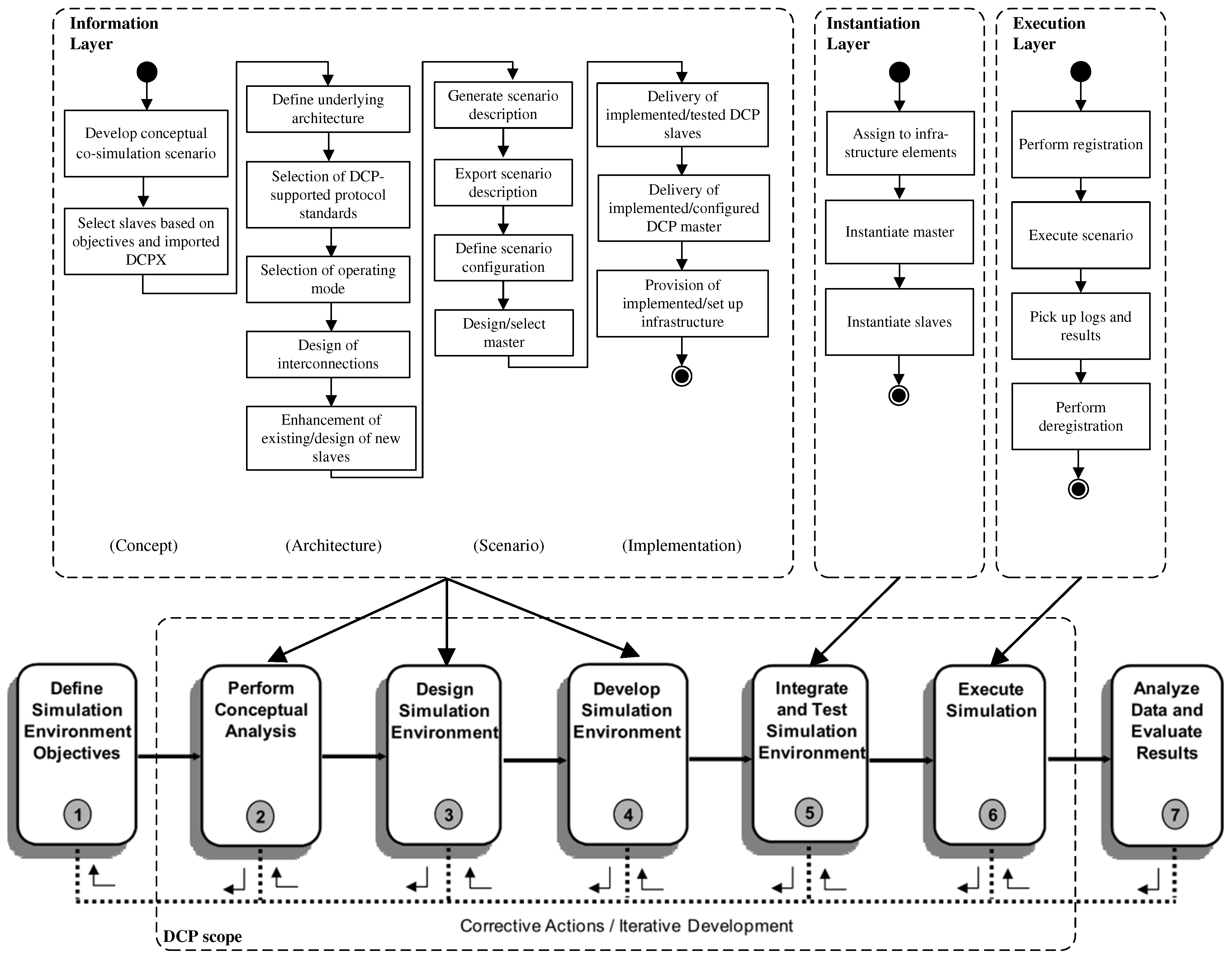
2. Process Model for Efficient Distributed Co-Simulation (ProMECoS)

2.1. Scope

In this article we introduce ProMECoS, a process model for efficient distributed co-simulation. ProMECoS is a process model targeted at the DCP in its first released version 1.0. It focuses on preparation, configuration, instantiation and execution of distributed co-simulations. However, ProMECoS is not to be mistaken for an architecture model, like the Reference Architecture Model Automotive (RAMA) [27] or the Automotive Open System Architecture (AUTOSAR) [28]. It does not reference specific system components, functions, or simulation use cases. Instead, ProMECoS is open to be integrated into such architecture models. For the FMI and the AUTOSAR standard this is shown in [29]. Therefore this article focuses on a generic process model.
The process model is designed as an overlay to IEEE 1730 [19], entitled “IEEE Recommended Practice for Distributed Simulation Engineering and Execution Process” (DSEEP). IEEE 1730 states that at a more abstract level, it is possible to identify a sequence of seven very basic steps that all distributed simulation applications will need to follow to develop and execute their simulation environments. Moving forward in the process, these steps must be performed sequentially. The process allows one to go back to any previous step at any time. IEEE 1730 avoids specifications of unnecessary constraints on how simulation environments are developed and executed. Furthermore, it provides a high degree of flexibility with regard to how supporting processes are organized and structured. ProMECoS aims to exploit these facts. Figure 3 shows the IEEE 1730 top-level process flow view (bottom) and related ProMECoS tasks organized in layers (top). During development of the DCP three different layers of system integration were identified [15]. On the information layer, all DCP artifacts, like the DCP master and all slaves of the intended co-simulation scenario, are subject to integration solely based on their meta-data. The DCP standard supports this approach by specification of the DCP slave description (DCPX) file format. On the instantiation layer, the real master and slaves are integrated with the communication system. As soon as all participants of the co-simulation are able to communicate, instantiation is complete. On the execution layer, the instantiated master and slaves dynamically interact with each other. Protocol data units (PDU) are sent and received using the specified transport protocol.
The three ProMECoS layers are allocated to the steps of IEEE 1730 as shown in Figure 3. The information layer covers IEEE 1730 steps 2, 3, and 4, the instantiation layer covers step 5, and the execution layer covers step 6. The DCP specification does not contribute to steps 1 and 7 by design. The definition of stakeholder needs, simulation environment objectives, and planning activities is not supported by any specific technical measures or definitions. The same holds for data analysis, evaluation, and feedback of results.

2.2. Mapping of Tasks

ProMECoS defines numerous tasks for each of its three layers. In forward direction, these tasks must be processed sequentially, due to logical dependencies and the flow of work products. All tasks of ProMECoS can be mapped to IEEE 1730 activities. This is shown in Table 3. The ProMECoS tasks and their identifiers are listed in the first two columns. In subsequent columns, the corresponding IEEE 1730 activities, identified by their number, are given. In the rows below, the character “x” indicates that DCP specific tasks match with these activities. Activities of IEEE 1730 that are not assigned a ProMECoS task may not be omitted automatically. The necessity for these activities must be evaluated during initial process tailoring. A typical example for such an activity is IEEE 1730 2.3, “Develop Simulation Environment Requirements”. The simulation environment requirements are written to guide further implementation activities in the process. Regarding the DCP, the requirements may target, e.g., computing platforms, operating systems, and networks. Hence, a DCP capable library may be compiled for usage on a specific operating system.

2.3. Process Artifacts

2.3.1. Integration Methodology and Roles

The DCP specification includes a non-mandatory integration methodology ([4], Section 10-B). It is shown in Figure 4. This default integration methodology is not a process description. Instead, it highlights the relationships between the most important DCP related artifacts. ProMECoS supports this integration methodology. The integration methodology is based on two fundamental roles, namely the “DCP slave provider” and the “DCP integrator”. As its name suggests, the slave provider is responsible for provision of a slave and its associated description to the integrator. A DCP slave is either a simulation model or a real-time system on a ready-to-run execution platform that is accessible via DCP over a given supported communication medium ([4], Section 3.1.3). The integrator’s tasks are related to import (see Section 2.3.2, ProMECoS Task 1.7), instantiation (see Section 2.4.5, ProMECoS Tasks 2.1, 2.2, 2.3), configuration (see Section 2.3.4, ProMECoS Task 1.10), and operation (see Section 2.3.5, ProMECoS Tasks 3.1–3.4) of at least one slave in a co-simulation scenario.

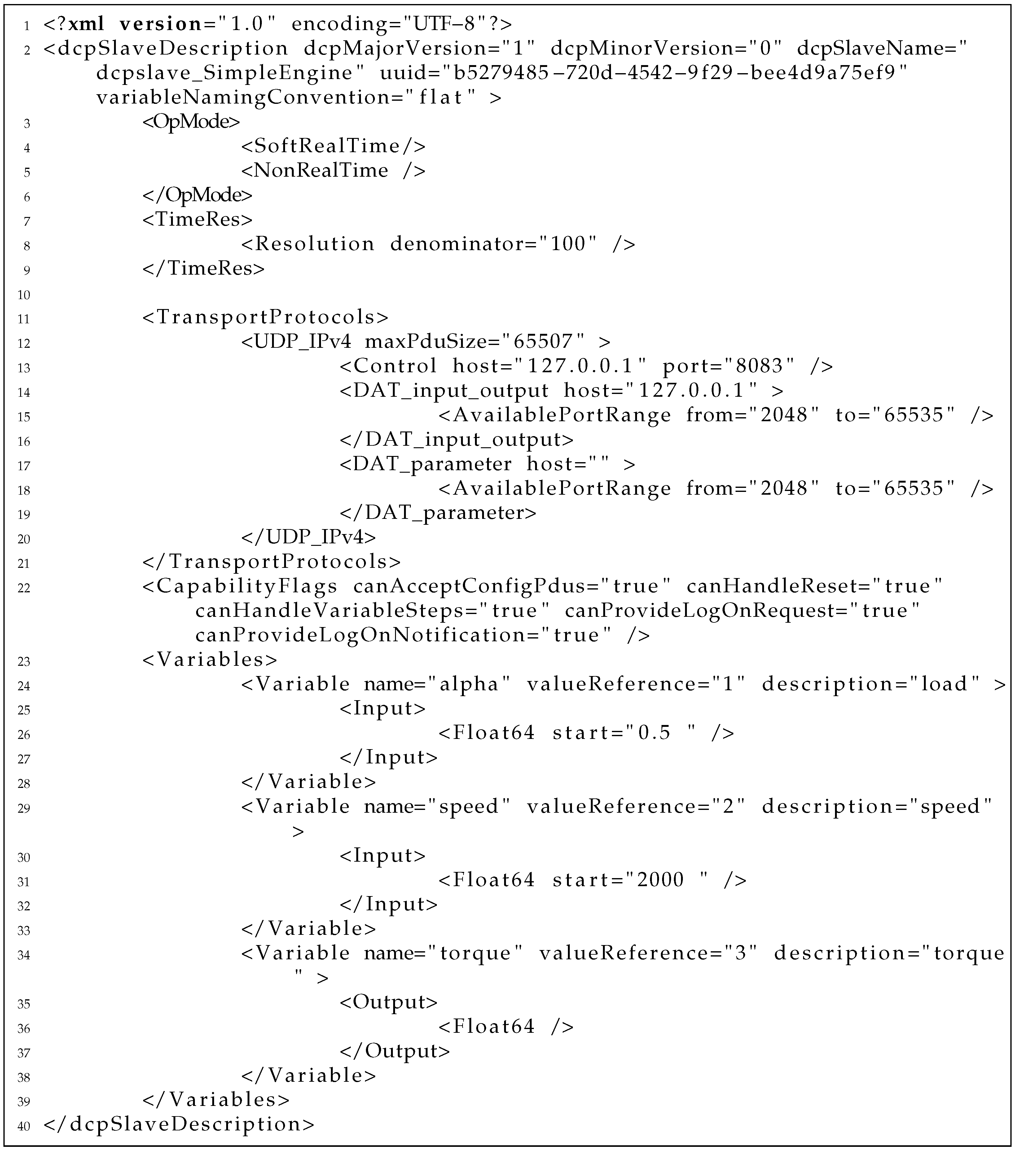
2.3.2. Generation and Description of DCP Slaves

A DCP slave can be realized on different computing platforms using different programing languages. It is essential that it is accessible via a supported transport protocol using DCP protocol data units (PDU). Communication must follow the specified protocol. Furthermore, one slave can only be controlled by exactly one master. Supported transport protocols of DCP version 1.0 are user datagram protocol (UDP/IPv4), transmission control protocol (TCP/IPv4), Bluetooth radio frequency communication (RFCOMM), Universal Serial Bus (USB), and controller area network (CAN, according to Kayak CAN definition, KCD). Typical examples for DCP slaves are software components, electronic control units (ECU), robotic components, real-time test equipment, or even large test rigs.
In order to enable the integration of a DCP slave into a larger co-simulation scenario, it must always be accompanied by a DCP file [13]. The DCP file is a zip encoded file [30] having the extension .dcp. This file must be consistent with the delivered slave at all times, to prevent erroneous assumptions about a slave’s features and capabilities. Its internal structure is normative and designed to hold multiple DCPX files which are compliant to different DCP version numbers. This is one example of several design provisions taken into account to provide a future-proof DCP specification. The DCP slave description (DCPX) is a Extensible Markup Language (XML) file which describes one single DCP slave. It contains all static information related to one specific DCP slave. Its structure is defined by a set of normative XML XML Schema Definition (XSD) files. The XSD schema does not only define the required structures of elements and attributes, but also supplementary assertions and constraints. Assertions and constraints are highly efficient for expressing logical relationships between elements and attributes.
Assertions are expressed in the xs:assert tag using the XML Path Language (XPath). An XPath expression addresses parts of an XML document in terms of a tree structure (Document Object Model, DOM). One location step in this tree consists of axis, node-test, and an optional predicate. An example for such an assertion is shown in Listing 1.
Listing 1. Assertion for capability flag and XML child element, as defined in the DCP slave description schema file [13].
Electronics 10 00633 g009
It links the capability flag canMonitorHeartbeat to the defined XML child element Heartbeat. This prevents, e.g., a set capability flag while the associated configuration information contained in the child element is missing. Assertions are a feature of XSD version 1.1. However, an XSL transformation (XSLT) file is specified, transforming the provided XSD version 1.1 schema definition file into a XSD version 1.0 schema definition file. Furthermore, xs:unique, xs:key and xs:keyref tags are used to express constraints. Typical examples of application include the verification of uniqueness of names and the verification of cross-referenced key values. In context of the DCP specification assertions and constraints provide strong formalisms which can be used for automated DCPX validation. This has shown to be advantageous in comparison to informal textual rules given in a specification document.

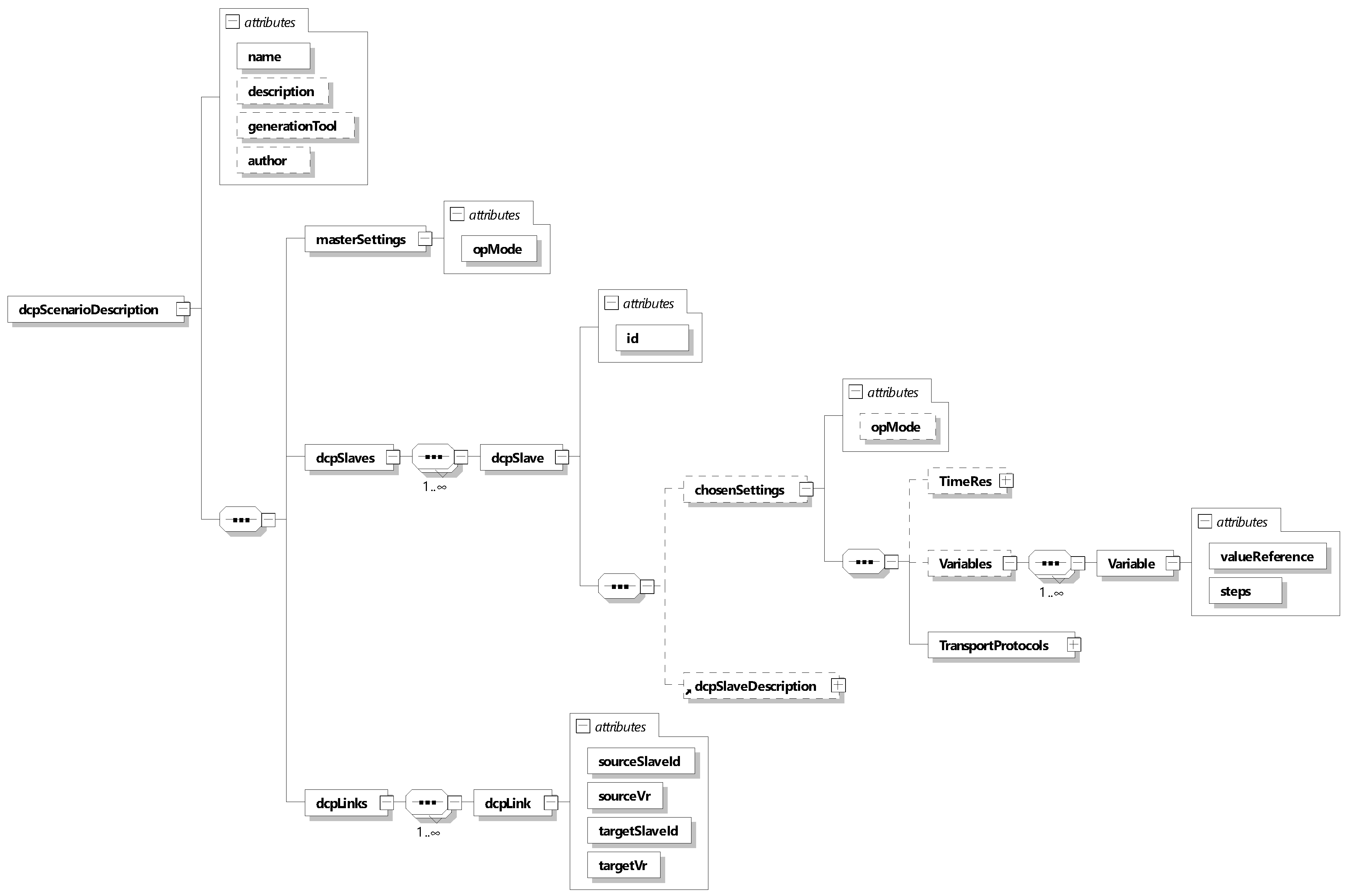
2.3.3. Information-Based Integration of Slaves and Scenario Description

A distributed co-simulation scenario is defined as the structural integration of multiple slaves to perform a common simulation task. Since the DCP file contains only information about one single slave, a data structure for representation of such scenarios is needed. For DCP, such a description file in terms of an XML schema description was proposed in [31]. Figure 5 shows the structure of this schema, including elements, groups and attributes.
The schema consists of three main branches. The masterSettings element has the attribute opMode to define the chosen operating mode for the scenario. The dcpSlaves element is dedicated to the slaves of the scenario. This element has one dcpSlave child element per slave. Within one scenario, one slave is uniquely identified by the slave identifier. The slave identifier is assigned by the creator of the scenario description. Each dcpSlave element has two child elements. The optional dcpDescription element is the root node of a copy of the DCP slave description. The chosenSettings element defines choices and selections made by the integrator. For example, this includes the time resolution actually used for simulation, since the slave description may provide multiple valid single resolutions or resolution ranges. The dcpLinks element contains the linkage of variables. It uses the previously defined slave identifiers and value references for unique definition of a single link.

2.3.4. Computation of Scenario Configurations

For each slave of a co-simulation scenario, transmitting at least one variable value to another slave, or receiving at least one variable from another DCP slave, a configuration must be distributed prior to data exchange. The DCP’s data exchange is organized by data ids. Variables assigned to one data id share common properties, e.g., receiver and time resolution. A valid configuration is represented by a set of configuration PDUs sent by the master. The DCP specification defines a separate PDU family for that. In case of a slave, which is unable to receive configuration PDUs, or non-native DCP [12,13] an agreement for a common configuration between slave providers and the integrator is needed prior to slave integration.
Depending on the targeted co-simulation scenario, the number of possible configurations can be high. In the long run, manual generation and preservation of a valid configuration is not reasonable, as it applies to exactly one unique co-simulation scenario. It seems more adequate to specify an algorithm for the calculation of a configuration. Based on the slave descriptions and scenario description on hand, this can be fully automated and is therefore considered a strength of the DCP standard.
For this task a group of suitable algorithms is proposed in [31]. This configuration problem can be seen as an instance of the 1D bin packing problem [32]. The classical one-dimensional bin packing problem is to pack a list of items into a number of bins. The bin packing problem translates to the DCP configuration problem, where the number of bins corresponds to the available data_ids. The DCP specification allows a maximum number of 2 16 data_ids. The items correspond to variable values identified by a value reference, having the length of their indicated data types. Based on this finding, four candidate algorithms were considered, namely First-Fit (FF), Best-Fit (BF), as well as their offline versions First-Fit-Decreasing (FFD) and Best-Fit-Decreasing (BFD). It is known that the offline versions perform better than the online versions, with respect to approximating an optimal solution [33,34]. Furthermore, in context of the DCP it is reasonable to select an offline algorithm, as all needed information is available at the time of configuration.
Figure 6 shows an illustrative example for three different possible configurations, resulting from different distributions of variables to data_ids. The considered scenario to generate these distributions included four slaves [31], with a total number of 75 connections for data exchange between them. The configurations were created using the FFD variant of bin packing algorithms. For 128 bytes data_id capacity, the scenario requires just 7 data_ids, the largest being 88 bytes. For 32 bytes data_id capacity, the scenario requires 15 data_ids. In this case, one data_id between some pairs of slaves is not sufficient anymore. The mapping from slave id 1 to slave id 2 now requires 3 data_ids, where two of them are of maximum size of 32 bytes. Finally, considering 8 bytes data_id capacity, the scenario requires a total number of 47 data_ids. The mapping from slave id 1 to slave id 2 now requires 11 data_ids, all of them are of size 8 bytes. All three distribution results are considered optimal w.r.t. bin utilization, since all data_ids between any two DCP slaves are of maximum given size, except the one with the highest data_id. Considering User Datagram Protocol over Internet Protocol Version 4 (UDP/IPv4) as the underlying transport protocol, the third configuration causes 3.2 times the bandwidth utilization compared to the first configuration. However, considering data losses, processing queues, and real-time requirements, smaller packet sizes may still be advantageous.

2.3.5. Use of a Master and Co-Simulation Execution

The definition of a DCP master is not covered by the DCP specification document. Its exact functionality and behaviour must be derived from requirements, imposed by the selected slaves of the co-simulation scenario. For example, if one slave requires the heartbeat feature to operate as intended, the master must be capable to send state request PDUs to this slave periodically at a given interval, as specified. Requirements like this can be determined through the available slave description files. General requirements for a master are elaborated in [35].
A master must be able to communicate using PDUs, using the same communication system and transport protocol as the slaves which are subject to be controlled. Therefore, it must be aware of the addressing scheme. In case of CAN bus based communication, the configuration is distributed prior to communication system start-up. In case of UDP/IPv4, the IP addresses can be obtained from the slave descriptions. If the slave descriptions do not contain IP addresses, the integrator needs to obtain them from another source, e.g., a network service like DHCP.
The DCP specification defines three different operating modes to cover different time domains [12]. In soft-real-time (SRT) operating mode the simulated time should be synchronous to wall clock time. In hard-real-time (HRT) operating mode the simulated time is synchronous to wall clock time. In non-real-time (NRT) operating mode the simulated time is independent from wall clock time. It can be faster or slower. The necessary real-time capabilities of a master depend on the co-simulation scenario. For example, if the entire co-simulation scenario consists of NRT DCP slaves, the master clocks the simulation. If NRT and SRT/HRT slaves are supposed to operate within one co-simulation scenario, the master must be able to clock the NRT DCP slaves at a frequency that corresponds to the resolution of the SRT/HRT DCP slaves.
Every standard compliant slave must operate according to the specified DCP state machine. During operation, this state machine passes through several phases.
Registration phase: In this phase, the master has started up and has access to information about DCP slaves that may potentially used for simulation. This can be achieved by reading DCP slave descriptions, using a network service, or talking to a network administrator. From a protocol perspective, the master sends a register PDU to each slave he needs to work with. As soon as these slaves have acknowledged such a registration attempt, they are controlled by this master exclusively. The register PDU also carries additional information. This includes the intended operating mode, the version of the DCP protocol to be used, and the universally unique identifier (UUID). The latter can be used to identify the slave implementation that corresponds to the slave description file.
Configuration phase: In the second phase, the master configures its registered slaves, by generating a valid configuration based on information contained in the slave description files. This configuration is then rolled out to all DCP slaves. If a slave cannot receive configuration PDUs, as indicated by the corresponding capability flag, this step is omitted.
Initialization phase: In the third phase, the master may trigger the initialization of all registered slaves. This means that an initial consistent state between all registered slaves shall be reached. To do so, the outputs of all slaves are computed based on input data. At the end of this phase, all slaves are prepared for the simulation phase. The scenario design for initialization is considered early in ProMECoS, as this may require the introduction of additional variables and connections.
Simulation phase: During the simulation phase the simulated time advances. It is dependent on the chosen operating mode. Input and output data of slaves are exchanged and test cases examined.
Stopping phase: Finally, the stopping phase is intended to stop the simulation in a safe way. While, e.g., simulation environments may be stopped immediately, any connected real-time systems may require some time to stop. After stop, slaves may be reset to be ready for the next simulation run, or deregistered and released from the master.
Error handling: Two states in the state machine are reserved for user-defined error handling procedures. The criteria for transition to these states are application specific and must be designed by the slave provider. This mechanism can be used to indicate a problem or failure that prevents the slave from continued operation. This way, a DCP slave can be treated as a safety-element-out-of-context (SEooC) [36]. As soon as one slave indicates that it has switched to the Error superstate, the master has the possibility to take action for the entire scenario. For example, the master may stop all other slaves that are still operating as intended, to prevent any damage to hardware and/or connected physical devices.

2.4. Task Descriptions

2.4.1. Concept

Task 1.1 “develop conceptual co-simulation scenario ” serves as a vehicle for transforming simulation objectives into functional and behavioral descriptions for DCP slave providers and especially the integrators. In IEEE 1730 this is also denoted as “conceptual model”. A conceptual model is the collection of information that describes a simulation developer’s concept about the simulation and its pieces [37]. The conceptual co-simulation scenario is implementation independent, the technologies and realizations behind DCP master and slaves are abstract. A language to support the development of such a conceptual model is the Systems Modeling Language (SysML) [38]. Approaches to develop a conceptual model for simulation purposes are described in [39,40]. A SysML profile dedicated to the DCP is available [15]. The DCP modeling language (DCPML) implements domain specific characteristics and defines an abstract syntax. Based on its fundamental language constructs, a range of stereotypes for modeling is defined. Four separate diagram types are available to cover different aspects of the simulation model. For a conceptual model, the Project Diagram and the Scenario Diagram are sufficient. The Dependency Diagram and the Slave Feature Diagram may be used afterward to complete the model and use it as a means for full scenario description.
In industry and academia alike, chances are good that single components for simulation are already available. For this reason, task 1.2, “selection of slaves”, evaluates these existing components. The slave provider must determine if an existing model or real-time system meets the requirements of the integrator, and if it is feasible to transform the system into a slave according to the DCP specification. If DCP slaves are already available, their slave descriptions are subject to evaluation.

2.4.2. Underlying Architecture

Despite the fact that ProMECoS focuses on application of the DCP, the relationship to the underlying simulation architecture and related standards is of great importance. Task 1.3 “define underlying architecture” addresses situations, where different communication systems, transport protocols, middlewares, and computing platforms should be used complementary to or in connection with the DCP. Gateways or bridges may be used to connect simulation participants and route simulation data across different networks. This also includes connection of legacy devices, which can be justified in a number of ways. Either a device is not able to run any software code, developers are not in favor to touch existing systems, or a belated DCP implementation is not reasonable from an economic point of view. An example for such a scenario is reported in [41]. In that paper, a cross-domain co-simulation is connected to a remote small-scale test bed using a device called PCM. The “Physical Converter Module” was developed in the ACOSAR project. It is intended to
  • enable DCP-based access to legacy devices that do not implement the DCP by themselves,
  • allow connections of real components and systems with simulations,
  • act as a gateway or router between different networks.
To provide this connectivity it features several different inputs and outputs. To connect physical components, four analogue and four digital inputs and just as many outputs are available. Furthermore, it provides two inputs for PT100 temperature sensors as well as brushless DC motor drivers. To establish DCP connections, two Ethernet ports, two CAN bus connectors, a USB port, and a Bluetooth interface (via USB) are available. The PCM is enclosed in a robust and compact aluminum case, which makes it suitable for usage in laboratories, test beds, and other industrial facilities.
Subsequently, task 1.4 deals with “selection of supported protocol standards”. This includes the underlying transport protocol for the DCP, but also the related transport protocols of connected communication systems. For example, the translation of DCP PDUs to CAN bus messages requires a dedicated algorithm. The underlying communication system and supported protocol standards directly affect real-time requirements of the targeted co-simulation scenario.
Therefore task 1.5, “selection of operating mode” determines real-time criteria for the entire co-simulation. For this task, the capabilities of the underlying communication systems and computational capacities of selected slaves are crucial. The choice of the operating mode significantly influences all subsequent tasks. Especially task 1.11 is affected, as the master must implement the specified operating mode. E.g., to operate a scenario including both SRT and NRT slaves, the master must be able to handle both in a coordinated way to achieve a SRT scenario.
Task 1.6 addresses the design of interconnections. This task defines connections between inputs, output, and parameters. On one hand, the integration of pure software components is affected by coupling errors. Solutions to this problem exist [5,6]. On the other hand, if co-simulation is extended to the real-time domain, coupling of models or real-time systems is affected by network delay and jitter [7,8]. A solution to that problem is proposed in [9]. If such coupling algorithms should be used to reduce coupling errors or compensate unwanted communication effects, they need to be addressed in this task.
Furthermore, it can be beneficial to start a distributed co-simulation scenario from a state that differs from its rest position. For this reason task 1.6 also addresses the development of initialization and synchronization strategies and procedures. Due to the causal dependencies between simulation participants, this often affects the entire co-simulation scenario or large portions of it. The co-simulation scenario must be brought into a state, where given variables must fulfill specified initial start conditions. The DCP supports initialization calculations to achieve a consistent initial condition of connected DCP slaves [13]. The DCP description file may contain information about a slave’s output dependencies. Such a dependency describes if an output is controllable by an input or parameter over time. Dependency information can be specified for the DCP’s Initialization and Run superstates separately. The first is applicable prior to simulation, whereas the latter is applicable during simulation. Additionally, a slave can mark outputs to be valid in Initialization superstate only, so-called initial outputs.
An example for such an initialization strategy is detection and break of cyclic dependencies. A cyclic dependency in a co-simulation scenario exists when two criteria are met. First, slaves are connected in a cyclic structure, also known as closed-loop simulation. Second, the affected outputs depend on their inputs. If such a cyclic dependency is detected, the integrator and the involved slave providers can make an attempt to break it. This would be possible by, e.g., adding additional parameters having dependencies from affected outputs. Initialization strategies may affect the entire co-simulation scenario in a way that additional inputs, outputs and parameters are required. If necessary, they must be designed in the subsequent task.
Task 1.7, “enhancement of existing and design of new slaves” is accomplished primarily by the slave providers. Based on the conceptual model created earlier and requirements stated by the integrator, each provider must come up with a plan for the slave design. This includes three steps. First, the model or real-time system which is subject to encapsulation in a DCP slave must be analyzed. If the real-time system is safety critical for operation within a co-simulation scenario, the applicable known failures must be identified. This can either be achieved by looking at available documentation, or conduction of a safety analysis. Second, the exposed interface of the real-time system must be analyzed. If an input signal shared via DCP is able to cause a failure on the real-time system, the DCP needs to address this issue. This is achieved in the third step. Criteria and transitions from the normal operation states to the error handling states must be defined (see Section 2.3.5). Variables may be monitored for updated values to detect data loss. Inputs and outputs may be prevented from overflowing with the introduction of additional delimiting functions. Note that this exact functionality is not covered by the DCP specification as it is highly use case specific. At the end of this task, each DCP slave provider should deliver a slave description to the integrator, the implemented slave follows later in task 1.12.

2.4.3. Scenario

Based on the conceptual model and the selected DCP slave description files the co-simulation scenario description must be developed. This is scheduled for task 1.8. Saving the scenario description using a specific file format (DCPS) is covered by task 1.9. In task 1.10, either a valid configuration is generated manually, or a suitable algorithm for configuration is chosen and implemented. After execution of the algorithm, the result is processed by the master. Task 1.11 is concerned with the design or selection of a suitable master. The scenario and slave description files serve as a basis for master requirements. Design or selection of a master can vary in complexity. Some important variability points are:
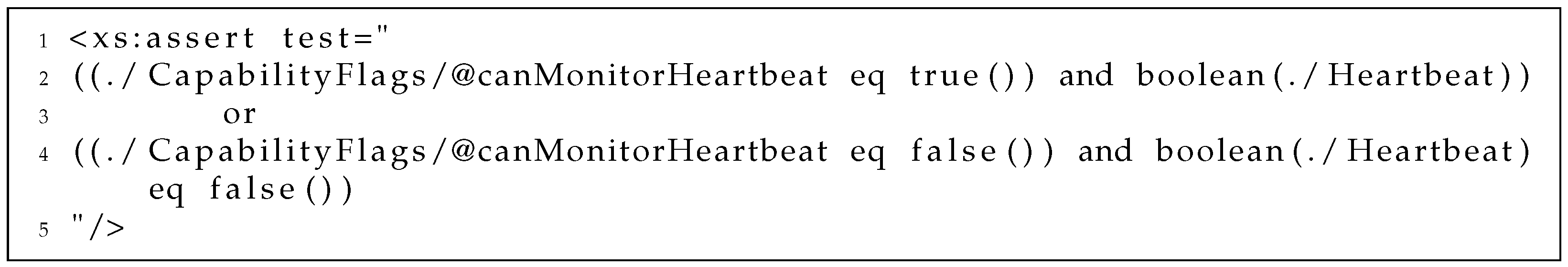
  • If a slave requires heartbeat monitoring to function properly, the master needs to be able to handle the affected PDUs accordingly.
  • If a slave requires roll out of a configuration, it must be able to prepare and send configuration PDUs.
  • If an initialization mechanism was developed earlier, the master must be able to trigger the appropriate states for calculation and data exchange during initialization superstate.
  • If the scenario includes indirect slave-to-slave communication, the master must be able to send and receive data PDUs.
  • If slaves are able to process reset PDUs, the master may trigger multiple simulation runs in a row without the need for reconfiguration.
Most of these points can be identified by analysis of the six capability flags that are defined in the slave description.

2.4.4. Implementation

At this point in ProMECoS, the specification of the scenario and its slaves, the master, and the infrastructure should have reached a maturity level that allows implementation of these artifacts. The main output of task 1.12 is a ready-to-run DCP slave, this is accomplished by each slave provider. Thorough verification of a slave is crucial for its release. In [14], a V-model for development, verification and validation of a DCP slave is proposed. In that work the idea of protocol-based verification is elaborated. Protocol-based verification can be used to test a slave for compliance to the DCP specification document. However, sending plain, pre-defined sequences of PDUs to slaves for protocol-based verification is not reasonable. A DCP slave may expose non-deterministic behaviour, due to, e.g., network delay, affecting the protocol and state machine ([4], p. 21). Protocol-based verification for DCP is based on a generic test procedure definition. This generic test procedure consists of steps and transitions between these steps. A transition corresponds to a sent or received DCP PDU. This generic test procedure definition is subject to extension. Test procedure extensions are based on the description of the slave-under-test, hence they can be tailor-made for each individual slave. This concept is supported by two open-source software projects. The DCP Test Generator (Available at https://github.com/modelica/DCPTestGenerator (accessed on 22 January 2021)) generates such tailor-made sequences of PDUs, and stores them in a separate test procedure XML file. The DCP Tester (Available at https://github.com/modelica/DCPTester (accessed on 22 January 2021)) mimics a master. It takes test procedure files as an input and stimulates the slave-under-test. A test procedure is successfully executed if the procedure returns at defined steps. Protocol-based test integrates seamlessly into other verification activities, e.g., and can be automated in an continuous-integration/continuous-delivery (CI/CD) software development approach.
An implemented and configured master is delivered by the integrator in task 1.13. The infrastructure for master and slaves is prepared in task 1.14. This includes network design, initialization and configuration of network elements, like transceivers and network adapters, setup of supporting software, as well as wiring and physical connections of network adapters. For Ethernet and IP-based networks the slave description schema file specifies that the statement of IP address and port information is optional. If the provider and integrator were able to agree on fixed IP addresses and ports beforehand, no more work needs to be done at this point. However, in reality the integrator strives for flexibility. The provider cannot foresee network addresses and ports to be used. In this case, the integrator must obtain and set this information in another way, which not specified. For that purpose, he might rely on other sources, e.g., the responsible network engineer or a service like dynamic host control protocol (DHCP).

2.4.5. Instantiation

The tasks assigned to the instantiation layer are used to take the now available master and slaves to the infrastructure. In task 2.1 preparatory work is done. If required, in case of IP-based networking, the integrator assigns IP addresses and port information obtained previously in task 1.14 to the master and slaves. Subsequently, the master and slaves are launched. The master is instantiated as soon as it is able to send PDUs, e.g., a state request INF_state (PDU). This is covered by task 2.2. A slave is instantiated as soon as it can be reached via DCP protocol, e.g., by answering a state request PDU with a corresponding response RSP_state_ack (PDU). This is covered by task 2.3.

2.4.6. Execution

According to the front-loading principle of DCP, at the execution layer all slaves and the master are running. All necessary measures were taken upfront so that the actual co-simulation can now be executed. ProMECoS assumes that all involved slave state machines are operated by the master in lock-step. This means that for normal operation all slaves are either within the same common current state s c , within the current state and the next requested state { s c , s c + 1 } , or within the current state, the next requested state and the state after the requested state { s c , s c + 1 , s c + 2 } . If all slaves have reached state s c + 1 or s c + 2 , this state becomes the new common current state. This alternative behavior depends on master-triggered or self-triggered state transitions, as specified in the DCP state machine. Self-triggered transitions are indicated using the prefix SIG_.
The following tasks of ProMECoS are aligned to the DCP state machine. In task 3.1 the master makes a registration attempt to each slave of the co-simulation scenario. If successful, the master takes exclusive control of each slave.
Task 3.2 is intended to execute the co-simulation scenario. The master controls the scenario to pass through the different phases of the state machine as described in Section 2.3.5. Therefore, it may use the calculated configuration, performs initialization and synchronization steps as designed, reacts to unexpected events in terms of error handling, and shuts down each slave of the scenario safely. In scope of this task, the encapsuled model or real-time system is used to execute the intended test cases.
Task 3.3 is related to the DCP’s logging features. Any collected log file entries may be picked up by the master at this point, after simulation and before deregistration.
Finally, task 3.4 is dedicated to deregistration. At deregistration the master releases its controlled slaves. The slaves may stay in state ALIVE, which allows them to be registered again. Alternatively they may also exit from DCP execution completely.

3. Application of ProMECoS

3.1. Use Case

To highlight the applicability of ProMECoS a use case from the automotive domain is considered. It is based on a real testbed application of AVL List GmbH (http://www.avl.com (accessed on 22 January 2021)). Various aspects of this use case are also described in [12,13,41]. The use case in this article aims at the demonstration of the interplay of ProMECoS process artifacts, performance evaluations (as conducted in [41]) are not in focus. Its complexity (primarily driven by the number of involved variables) was reduced for simplified comprehension and better legibility. Power train and full vehicle test benches are typically used for integration and performance tests. Especially for new propulsion systems, like hybrid electric vehicles or battery electric vehicles, interplay of subsystems for optimal energy consumption and efficiency is of utmost importance. To measure energy consumption and assess propulsion efficiency, power train components like combustion engines, electric motors, batteries and inverters are connected with a dynamometer. In this example, we propose an engine, mounted onto a testbench, and a vehicle model including a driver. Due to the fact that the industrial utilization of test benches is typically high and their use costly, a MiL simulation is set up before moving on to a HiL test rig. Because of that a model of the engine is used. The efficiency of setting up such a DCP-based co-simulation scenario relies on the following key capabilities:
  • Existing models can be reused. This holds true for FMUs, which can be seamlessly embedded into DCP slaves.
  • MiL simulation is performed in NRT mode, but can be switched to SRT mode before integrating real hardware.
  • A model can be replaced with its real counterpart system, sharing the same inputs, outputs, and parameters.
The goal is to simulate the driving performance of a given vehicle including a real engine on a test bench following a Worldwide harmonized Light vehicle Test Procedure (WLTP) test cycle. WLTP was developed by the “United Nations Economic Commission for Europe” (UNECE) to replace the “New European Driving Cycle” (NEDC) as the European vehicle homologation procedure. The final WLTP specification was released in 2015. These objectives account for step 1 of  IEEE 1730.
ProMECoS starts with the development of a conceptual co-simulation scenario. In this case, three components can be identified.
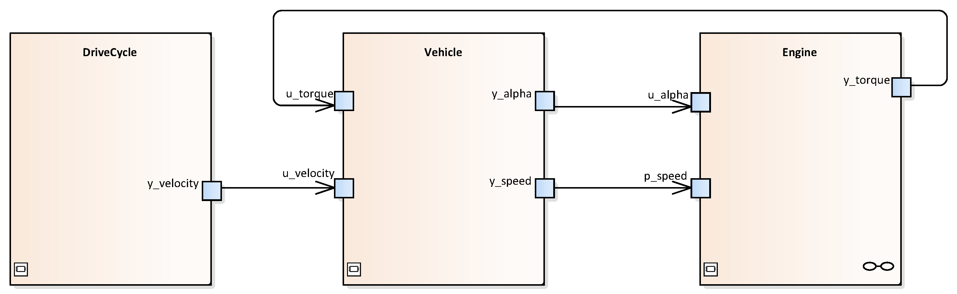
  • The engine model has inputs for the accelerator pedal and rotating shaft speed. It communicates the required torque demand to the vehicle model.
  • The vehicle model has inputs for the torque demand and desired vehicle velocity. Based on the current load, it communicates the accelerator pedal position and rotating shaft speed to the engine model. The vehicle model includes a driver model.
  • The drive cycle model communicates the required vehicle velocity to the driver inside the vehicle model.
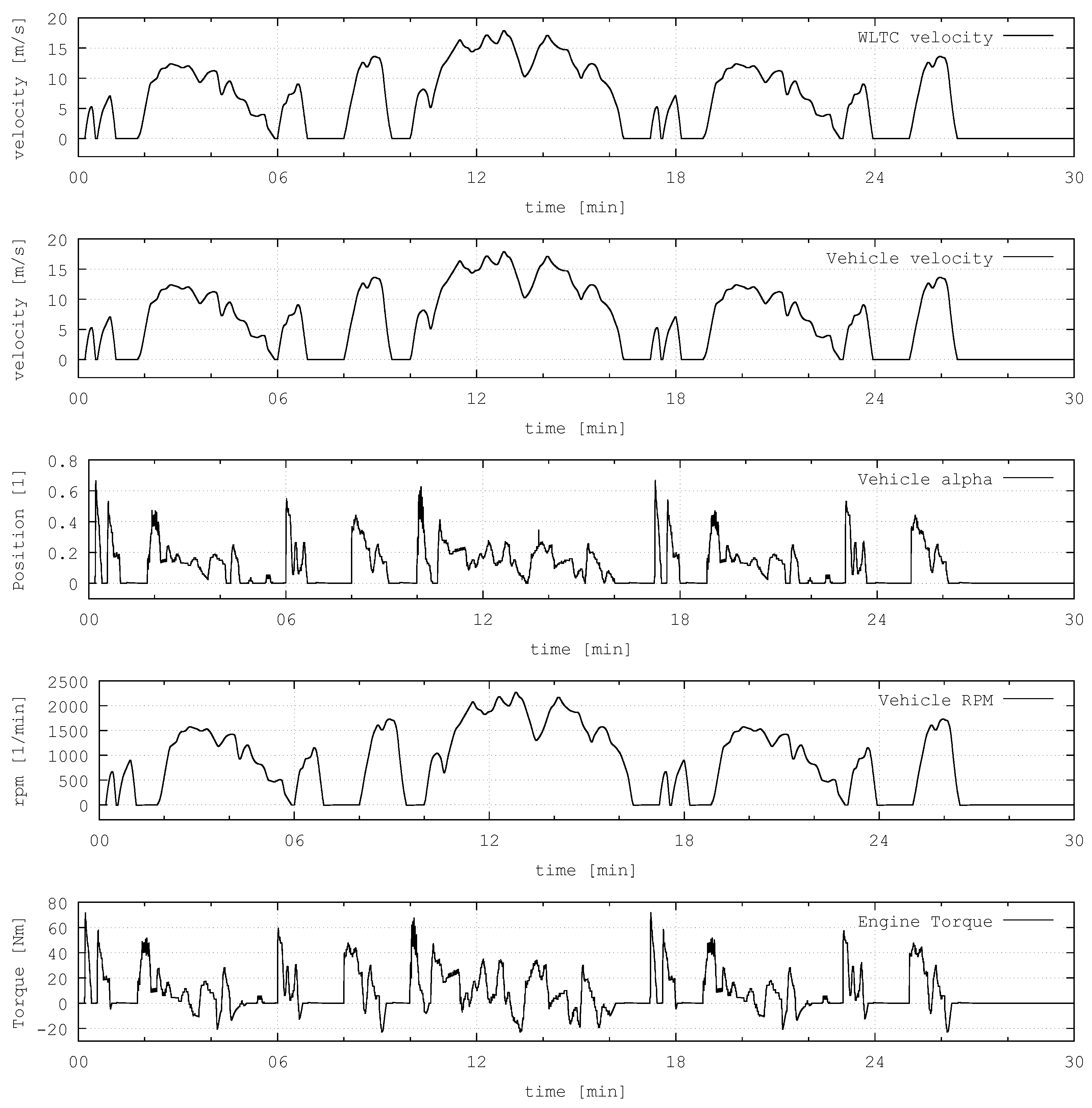
This co-simulation scenario was modeled using a prototypical implementation of DCPML [15] for Enterprise Architect by SparxSystems. Figure 7 shows a scenario diagram, including stereotypes for three slaves (vehicle, engine, and drive cycle). Ports are used to represent the inputs and outputs of these slaves. They are linked using connectors. The initial conceptual DCPML model is enriched with additional information as ProMECoS progresses. This is achieved using additional property elements and tagged values. The resulting model can be transformed into DCPX files and the overall DCPS file. This functionality was prototypically implemented in terms of an add-in for Enterprise Architect, exporting these artifacts.
Listing 2 shows the engine’s DCP slave description. It represents a simulation model, based on a combustion engine’s curve family. Line 2 contains meta information about the slave. In lines 4 and 5 the operating mode is declared. On one hand this model is designed for pure software simulation in non-real-time operating mode. On the other hand the model’s soft-real-time operating mode makes it suitable for real-time simulations. The model’s time resolution is specified in line 8, where the denominator value if given. The numerator value is not explicitly specified. In such a situation, the slave description schema file may be used to pull default values. This approach helps to reduce redundant transmission of configuration information and can be automated by using a parser supporting XML schema definitions and the DCPX schema file itself. Lines 11 to 21 are used for transport protocol related settings, in this case UDP over IPv4 is used on a local host. Line 22 lists the slave’s capability flags. In lines 23 to 39 the three variables are defined (accelerator pedal position, shaft speed and torque demand).
Listing 2. DCP slave description file representing the engine model.
Electronics 10 00633 g010
For the DCP scenario description, the proposed DCPS file format was used. An excerpt of that file is shown in Listing 3. In line 3 the overall operating mode is defined, so the master is informed that this will be executed as a soft-real-time simulation. From line 4 to 23 the slave identifiers are assigned. Furthermore, each slave is assigned a local operating mode. From line 24 to 30, the interconnections between slaves are described as links. The file is shortened, as each slave’s description is contained in the scenario description.
Listing 3. Excerpt of the used DCP scenario description file.
Electronics 10 00633 g011
Since this concrete scenario contains only four links between three slaves, a pragmatic approach for generation of a scenario configuration was applied. For each slave sending at least one output variable to another slave, one data_id is used for that purpose. This is possible since all outputs sent from slave 1 to slave 2 share the same step size (1) and resolution (1/100th of a second). Listing 4 shows part of the rolled out configuration. It contains all PDUs and their fields transmitted to the slave representing the engine (slave_id = = 1 ). On line 4 and 5 two PDUs are used to configure the same data_id for two input variables.
All slaves and the master were implemented using DCPLib (Available at https://github.com/modelica/DCPLib (accessed on 22 January 2021)), an open-source software library written in C++ programming language. It provides several packages: The DCPLib::Core package contains common classes like constants and PDU definitions. The DCPLib::Slave package is needed to create slaves. At this point in time, DCPLib supports ethernet networks for UDP and TCP over IP version 4 support. Furthermore, DCPLib::Xml and DCPLib::Zip support the handling of DCP files. The DCPLib::Master package contains the necessary functionality for construction of a master. However, DCPLib does not include any coupling algorithms or automation functions.
For the slave representing the engine, an existing FMU was successfully encapsulated using DCPLib. From an operational point of view, this is achieved by mapping the states of the DCP state machine with the states of the FMI state machine. Subsequently, received PDUs can trigger FMU functions, and called FMU functions can also trigger sending of PDUs. Table 4 shows the used mapping. FMI’s Initialization Mode is covered by DCP’s CONFIGURED, INITIALIZING, INITIALIZED, and SENDING_I states, denoted as superstate Initialization. In this use case, the vehicle starts to move from standstill, hence no additional precalculations before the start of simulated time are necessary. The DCP’s states COMPUTING, COMPUTED, and SENDING_D are only required if the slave is executed in non-real-time operating mode. FMI’s stepInProgress and slaveInitialized must be available from SYNCHRONIZING throughout to SENDING_D, in order to enable both real-time and non-real-time operating modes for the slave.
Listing 4. The configuration rolled out to slave 1.
Electronics 10 00633 g012
The three DCP slaves and the master were instantiated on different computers in the testing lab. After that, the tasks of the execution layer started. Listing 5 shows the DCP related communication between the master and the vehicle model, which is assigned slave identifier 2. The simulation results were acquired from all slaves after execution of ProMECoS, in step 7 of IEEE 1730. Figure 8 shows the values over time for each output variable of the scenario, including the actual vehicle velocity.
Listing 5. Registration of the vehicle model. At the same time it is assigned slave identifier 2.
Electronics 10 00633 g013

3.2. Analysis

The described use case was successfully built, instantiated and executed according to ProMECoS. Since the 30 min WLPT profile starts from vehicle standstill, no initialization had to be used. The step-size was set to 10 ms, resulting in a total number of 180.000 steps in NRT and SRT operating mode. On standard office computers with data exchange over standard Ethernet network, this leads to a computation time in NRT mode of 3:50 min. All introduced process artifacts gear into each other to achieve the goal of front-loading:
  • The conceptual model identified the required slaves, where one of them (the engine model) was available from a previous model-in-the-loop simulation as a FMU. In course of the process, it was encapsulated in a DCP slave.
  • The roles of providers and the integrator were assigned to respective persons and companies.
  • The underlying communication architecture is based on an Ethernet network. The UDP transport protocol was used for this distributed co-simulation. The operating mode was set to NRT, to prepare the scenario for future connection to a real automotive test bench operated in SRT mode. The conceptual model was used to generate the scenario description file.
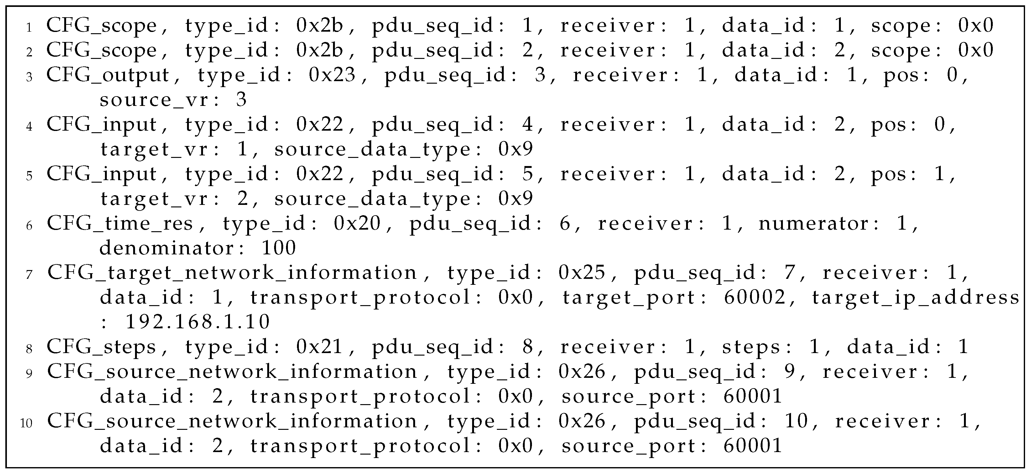
  • Based on the scenario description file, a configuration was generated. Due to the manageable amount of of interconnections between slaves, each variable was manually assigned to a separate data_id or UDP packet. During scenario execution, it was rolled out by the master to the three slaves.
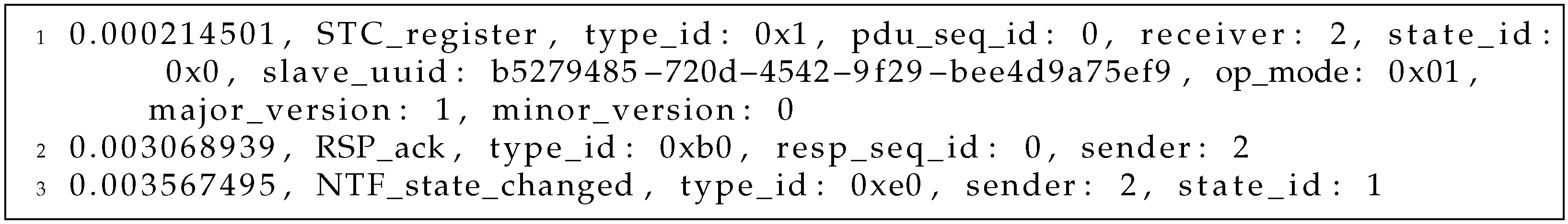
  • The master was tailor-made for the scenario at hand using DCPLib. The instantiation and execution was performed on two networked computers in our lab.
Following ProMECoS, the effort to extend this co-simulation scenario by connecting remote facilities, like engine test beds, is considered minimal if the facility shares the same DCP interface. DCP-based use cases including the integration of test beds are also described in [12,13,42]. Furthermore, the successful remote integration of slaves over the internet is described in [41].
At this point in time, DCPLib implements the DCP specification only, and does not offer countermeasures to deal with coupling errors. Industrial commercial software simulation tools implementing patented solutions to these problems are available (Model.CONNECT by AVL List GmbH, www.avl.com (accessed on 22 January 2021)) The application and configuration of such mechanisms is not in scope of this article. However, ProMECoS considers the integration of such mechanisms in Task 1.6.

4. Conclusions

ProMECoS is a systematic way to set up distributed co-simulations using the DCP. It can be applied to integrate simulation models and also real-time systems. In contrast to other simulation architectures, like HLA for example, ProMECoS embeds a wire-protocol definition in connection with native and non-native DCP mappings. It relies on lightweight artifacts, including the slave descriptions, the scenario description, the mapping of PDUs to a transport protocol, the generated co-simulation configuration, the executable slaves themselves, and the master controlling the co-simulation. The entire process is designed to be IEEE 1730 compatible, which means that all ProMECoS tasks can be mapped to an IEEE 1730 activity. The design of the DCP specification fosters the front-loading principle, hence ProMECoS takes advantage of this property. A corresponding distributed co-simulation can be planned and designed completely, before moving on to instantiation and execution. ProMECoS covers the FMI standard indirectly, as a DCP slave may include a single FMU, or even an FMI-based co-simulation scenario. In such a situation, the model description file of the FMU must also be considered as a usable artifact during the design of a new DCP slave.
ProMECoS has a high potential for automation. The process artifacts are well-defined, and can be created, modified, analyzed, validated and processed in an automated way. This was also one of the main aspects during development of the DCP. For example, the DCP slave description schema files not only specify the structure of XML data. They were also enriched with numerous assertions and constraints, enabling instant validation of static slave data. The same holds true for other artifacts, like the scenario description file.
ProMECoS represents the first attempt to come up with a defined process for distributed co-simulation in context of the DCP specification. However, it has some limitations, that could be addressed in future work:
  • The integration of ProMECoS and the DCP standard into architecture models (RAMA, AUTOSAR, etc.) requires further research.
  • In the future, the DCP scenario description might be replaced by standardized system structure and parameterization [43] (SSP) XML files.
  • ProMECoS does not cover step 1 (definition of objectives) and 7 (analysis of results) of IEEE 1730, as these activities are out of scope of the DCP specification. Nevertheless the formulation of objectives and analysis of results represent highly relevant topics for distributed co-simulation in context processes and standards, and are therefore subject to further research.
  • Within steps 2–6, the DCP specification targets the specification and design of a slave only. The features and capabilities of the required master are not defined by the DCP specification. A master, which is mandatory, can be of high complexity, e.g., when different operating modes like NRT and SRT are mixed in one scenario. Scenarios like this represent an interesting field for future work, as such master algorithms will be needed in, e.g., HiL settings.
  • Furthermore, ProMECoS assumes co-simulation scenarios with slaves in lock step operation. This means that all slaves are registered, configured, initialized, synchronized, used for simulation, and shut down at the same time, disregarding delays and other effects contributing to non-determinism. Not operating slaves in lock step implies severe consequences, like the definition of synchronization points for dynamic addition or removal of slaves during simulation. This is expected to be required in the future, especially in context of IoT (internet-of-things, see [26]), digital twins and virtual validation. This is an open issue not only in ProMECoS, but in the specification of the DCP standard, and is therefore subject to further research.
  • At this point in time, DCP supports five transport protocols for different communication systems. It provides a framework for addressing connection-oriented and connection-less, reliable and unreliable, as well as native and non-native transport protocols. If the necessity for adoption of new protocols arises in the future, ProMECoS and the DCP specification may both be subject to modifications.
All in all, the DCP is used in research and industry to address the need for distributed co-simulation. ProMECoS contributes to the simulation and test community by offering a systematic approach to execution of such simulations.

Author Contributions

Conceptualization, M.K. and M.B.; methodology, M.K.; software, C.S.; validation, M.K. and C.S.; writing—original draft preparation, M.K.; writing—review and editing, M.K., M.B. and C.S. All authors have read and agreed to the published version of the manuscript.

Funding

Virtual Vehicle Research GmbH has received funding within COMET Competence Centers for Excellent Technologies from the Austrian Federal Ministry for Climate Action, the Austrian Federal Ministry for Digital and Economic Affairs, the Province of Styria (Dept. 12) and the Styrian Business Promotion Agency (SFG). The Austrian Research Promotion Agency (FFG) has been authorised for the programme management.

Conflicts of Interest

The authors declare no conflict of interest.

References

  1. Geimer, M.; Krüger, T.; Linsel, P. Co-Simulation: Gekoppelte Simulation oder Simulatorkopplung. In O+ P Zeitschrift für Fluidtechnik; GBI-Genios: Munich, Germany, 2006; pp. 4–8. [Google Scholar]
  2. Snowden, D. Cynefin, A Sense of Time and Place: An Ecological Approach to Sense Making and Learning in Formal and Informal Communities. In Proceedings of the Conference Proceedings of KMAC, Birmingham, UK, 17–18 July 2000. [Google Scholar]
  3. Thomke, S.; Fujimoto, T. The Effect of “Front-Loading” Problem-Solving on Product Development Performance. J. Prod. Innov. Manag. 2000, 17, 128–142. [Google Scholar] [CrossRef]
  4. Modelica Association Project DCP. DCP Specification Document; Version 1.0; Modelica Association: Linköping, Sweden, 2019. [Google Scholar]
  5. Benedikt, M.; Hofer, A. Guidelines for the application of a coupling method for non-iterative co-simulation. In Proceedings of the 8th EUROSIM Congress on Modelling and Simulation, EUROSIM 2013, Wales, UK, 10–13 September 2013; pp. 244–249. [Google Scholar] [CrossRef]
  6. Benedikt, M.; Watzenig, D.; Zehetner, J.; Hofer, A. NEPCE—A nearly energy-preserving coupling element for weak-coupled problems and co-simulations. In Proceedings of the Computational Methods for Coupled Problems in Science and Engineering V—A Conference Celebrating the 60th Birthday of Eugenio Onate, COUPLED PROBLEMS 2013, Ibiza, Spain, 17–19 June 2013; pp. 1021–1032. [Google Scholar]
  7. Stettinger, G.; Zehetner, J.; Benedikt, M.; Thek, N. Extending Co-Simulation to the Real-Time Domain; SAE Technical Papers; SAE: Warrendale, PA, USA, 2013; Volume 2. [Google Scholar] [CrossRef]
  8. Stettinger, G.; Benedikt, M.; Thek, N.; Zehetner, J. On the difficulities of real-time co-simulation. In Proceedings of the Computational Methods for Coupled Problems in Science and Engineering V—A Conference Celebrating the 60th Birthday of Eugenio Onate, Coupled Problems 2013, Ibiza, Spain, 17–19 June 2013; pp. 989–999. [Google Scholar]
  9. Stettinger, G.; Horn, M.; Benedikt, M.; Zehetner, J. Model-based coupling approach for non-iterative real-time co-simulation. In Proceedings of the 2014 European Control Conference, ECC 2014, Strasbourg, France, 24–27 June 2014; pp. 2084–2089. [Google Scholar] [CrossRef]
  10. Modelisar Consortium; Modelica Association Project “FMI”. Functional Mock-Up Interface for Model Exchange and Co-Simulation; Version 2.0.2; Modelica Association: Linköping, Sweden, 2020. [Google Scholar]
  11. Blochwitz, T.; Otter, M.; Arnold, M.; Bausch, C.; Clauß, C.; Elmqvist, H.; Junghanns, A.; Mauss, J.; Monteiro, M.; Neidhold, T.; et al. The Functional Mockup Interface for Tool independent Exchange of Simulation Models. In Proceedings of the 8th International Modelica Conference, Dresden, Germany, 20–22 March 2011; pp. 105–114. [Google Scholar] [CrossRef] [Green Version]
  12. Krammer, M.; Benedikt, M.; Blochwitz, T.; Alekeish, K.; Amringer, N.; Kater, C.; Materne, S.; Ruvalcaba, R.; Schuch, K.; Zehetner, J.; et al. The Distributed Co-simulation Protocol for the Integration of Real-time Systems and Simulation Environments. In Proceedings of the 50th Computer Simulation Conference, Society for Computer Simulation International, SummerSim’18. San Diego, CA, USA, 22–24 July 2018; pp. 1:1–1:14. [Google Scholar]
  13. Krammer, M.; Schuch, K.; Kater, C.; Alekeish, K.; Blochwitz, T.; Materne, S.; Soppa, A.; Benedikt, M. Standardized Integration of Real-Time and Non-Real-Time Systems: The Distributed Co-Simulation Protocol. In Proceedings of the 13th International Modelica Conference, Regensburg, Germany, 4–6 March 2019; Volume 157, pp. 87–96. [Google Scholar] [CrossRef] [Green Version]
  14. Krammer, M.; Kater, C.; Schiffer, C.; Benedikt, M. A Protocol-Based Verification Approach for Standard-Compliant Distributed Co-Simulation. In Proceedings of the Asian Modelica Conference 2020, Tokyo, Japan, 8–9 October 2020; Volume 174, pp. 133–142. [Google Scholar] [CrossRef]
  15. Krammer, M.; Benedikt, M. Design and application of a domain specific modeling language for distributed co-simulation. In Proceedings of the IEEE International Conference on Industrial Informatics (INDIN), Helsinki-Espoo, Finland, 15 March–22 April 2019; pp. 677–682. [Google Scholar]
  16. Martinen, D.H.; Lagalaye, M.; Pfefferkorn, J.; Casteres, J. Modular and Open Test Bench Architecture for Distributed Testing. In Proceedings of the AeroTech Congress and Exhibition, Fort Worth, TX, USA, 26–28 September 2017; SAE International: Warrendale, PA, USA, 2017. [Google Scholar] [CrossRef]
  17. Straßburger, S. Overview about the High Level Architecture for Modelling and Simulation and Recent Developments. Simul. News Eur. 2006, 16, 5–14. [Google Scholar]
  18. Albagli, A.N.; Falcão, D.M.; De Rezende, J.F. Smart grid framework co-simulation using HLA architecture. Electr. Power Syst. Res. 2016, 130, 22–33. [Google Scholar] [CrossRef]
  19. IEEE Computer Society. IEEE Recommended Practice for Distributed Simulation Engineering and Execution Process (DSEEP), 1st ed.; Institute of Electrical and Electronics Engineers: New York, NY, USA, 2011. [Google Scholar]
  20. Bocciarelli, P.; D’Ambrogio, A.; Durak, U.; Panetti, T. Rethinking Simulation Engineering Process for MSaaS. In Proceedings of the IEEE 29th International Conference on Enabling Technologies: Infrastructure for Collaborative Enterprises (WETICE), Bayonne, France, 23–25 June 2021; pp. 88–93. [Google Scholar] [CrossRef]
  21. Leitner, A.; Zehetner, J.; Toeglhofer, P.; Watzenig, D. Requirement identification for variability management in a co-simulation environment. In Proceedings of the 16th International Software Product Line Conference on—SPLC’12, Munich, Germany, 22–26 August 2012; ACM Press: New York, NY, USA, 2012; Volume 1, p. 269. [Google Scholar] [CrossRef]
  22. Krammer, M.; Marko, N.; Benedikt, M. Interfacing real-time systems for advanced co-simulation—The ACOSAR approach. In CEUR Workshop Proceedings; Dubois, C., Parisi-Presicce, F., Kolovos, D., Matragkas, N., Eds.; Dubois, Catherine Parisi-Presicce, Francesco Kolovos, Dimitris Matragkas, Nicholas: Vienna, Austria, 2016; Volume 1675, pp. 32–39. [Google Scholar]
  23. Broy, M. Challenges in automotive software engineering. In Proceeding of the 28th International Conference on Software Engineering ICSE 06, Shanghai, China, 20–28 May 2006; Volume 2006, p. 33. [Google Scholar] [CrossRef]
  24. HLA Working Group. IEEE 1516-2010—IEEE Standard for Modeling and Simulation (M&S) High Level Architecture (HLA)—Framework and Rules; IEEE Computer Society: Washington, WA, USA, 2010. [Google Scholar]
  25. Guerra, R.H.; Quiza, R.; Villalonga, A.; Arenas, J.; Castano, F. Digital Twin-Based Optimization for Ultraprecision Motion Systems with Backlash and Friction. IEEE Access 2019, 7, 93462–93472. [Google Scholar] [CrossRef]
  26. Jung, T.; Shah, P.; Weyrich, M. Dynamic Co-Simulation of Internet-of-Things-Components using a Multi-Agent-System. Procedia CIRP 2018, 72, 874–879. [Google Scholar] [CrossRef]
  27. Security Sub-Working Group “Connected and Automatic Driving”. In TFCS-08-05: Reference Architecture Model Automotive (RAMA); Governmental Department of Transport and Infrastructure (BMVI): Berlin, Germany, 2019.
  28. Staron, M.; Durisic, D. AUTOSAR Standard. In Automotive Software Architectures: An Introduction; Springer International Publishing: Cham, Switzerland, 2017; pp. 81–116. [Google Scholar] [CrossRef]
  29. Thiele, B.; Henriksson, D. Using the Functional Mockup Interface as an Intermediate Format in AUTOSAR Software Component Development. In Proceedings of the 8th International Modelica Conference, Dresden, Germany, 20–22 March 2011; Volume 63, pp. 484–490. [Google Scholar] [CrossRef] [Green Version]
  30. ISO/IEC JTC 1/SC 34. Information Technology—Document Container File—Part 1: Core; Standard; International Organization for Standardization: Geneva, Switzerland, 2015. [Google Scholar]
  31. Krammer, M.; Benedikt, M. Configuration of Slaves Based on the Distributed Co-Simulation Protocol. In Proceedings of the IEEE International Conference on Emerging Technologies and Factory Automation, ETFA, Torino, Italy, 4–7 September 2018; pp. 195–202. [Google Scholar] [CrossRef]
  32. Korte, B.; Vygen, J. Combinatorial Optimization: Theory and Algorithms (Algorithms and Combinatorics); Springer: Berlin/Heidelberg, Germany, 2005. [Google Scholar]
  33. Johnson, D.S.; Demers, A.; Ullman, J.D.; Garey, M.R.; Graham, R.L. Worst-Case Performance Bounds for Simple One-Dimensional Packing Algorithms. SIAM J. Comput. 1974, 3, 299–325. [Google Scholar] [CrossRef] [Green Version]
  34. Korf, R.E. A new algorithm for optimal bin packing. In Proceedings of the AAAI/IAAI, Edmonton, AB, Canada, 28 July–1 August 2002; pp. 731–736. [Google Scholar]
  35. Krammer, M.; Benedikt, M. Master for Simulation Control using the Distributed Co-Simulation Protocol. In Proceedings of the IEEE 16th International Conference on Industrial Informatics, INDIN 2018, Porto, Portugal, 18–20 July 2018; pp. 329–334. [Google Scholar] [CrossRef]
  36. Krammer, M.; Martin, H.; Winkler, B.; Benedikt, M. Functional Safety in the Context of Distributed Co-Simulation. In Proceedings of the Twenty-Seventh Safety-Critical Systems Symposium, Bristol, UK, 5–7 February 2019; Parsons, M., Kelly, T., Eds.; Safety Critical Systems Club: Bristol, UK, 2019. [Google Scholar]
  37. Pace, D.K. Ideas about simulation conceptual model development. Johns Hopkins Apl Tech. Dig. (Appl. Phys. Lab.) 2000, 21, 327–336. [Google Scholar]
  38. Object Management Group. OMG Systems Modeling Language (OMG SysML); Version 1.6; Object Management Group: Needham, MA, USA, 2019. [Google Scholar]
  39. Robinson, S.; Brooks, R.J.; Kotiadis, K.; van der Zee, D.J. Conceptual Modeling for Discrete-Event Simulation; CRC Press: Boca Raton, FL, USA, 2010. [Google Scholar] [CrossRef]
  40. Huang, E.; Ramamurthy, R.; McGinnis, L.F. System and simulation modeling using SYSML. In Proceedings of the 2007 Winter Simulation Conference, Washington, WA, USA, 9–12 December 2007; pp. 796–803. [Google Scholar] [CrossRef] [Green Version]
  41. Baumann, P.; Krammer, M.; Driussi, M.; Mikelsons, L.; Zehetner, J.; Mair, W.; Schramm, D. Using the Distributed Co-Simulation Protocol for a Mixed Real-Virtual Prototype. In Proceedings of the 2019 IEEE International Conference on Mechatronics, ICM 2019, Ilmenau, Germany, 18–20 March 2019; IEEE Industrial Electronics Society: Ilmenau, Germany, 2019; pp. 440–445. [Google Scholar] [CrossRef]
  42. Krammer, M.; Marko, N.; Benedikt, M. Requirements engineering for consensus-oriented technical specifications. In Proceedings of the 2018 IEEE 26th International Requirements Engineering Conference, RE 2018, Banff, AB, Canada, 20–24 August 2018; pp. 315–324. [Google Scholar] [CrossRef]
  43. Modelica Association Project SSP. SSP Specification Document, version 1.0; Modelica Association: Linköping, Sweden, 2019. [Google Scholar]
Figure 1. Front loading benefits of simulation driven development of cyber-physical systems over time.
Electronics 10 00633 g001
Figure 2. The DCP concept [22]. A co-simulation environment (left) should connect to a real-time system (right). The DCP (center) can be mapped to a transport protocol, which uses a communication system.
Electronics 10 00633 g002
Figure 3. General process flow of ProMECoS and IEEE 1730.
Electronics 10 00633 g003
Figure 4. The default integration methodology and its artifacts [4], highlighting the provider (center) and integrator roles ((left) and (right)).
Electronics 10 00633 g004
Figure 5. Graphical representation of the proposed XML schema for DCP scenario description, based on [31].
Electronics 10 00633 g005
Figure 6. Exemplary distribution results of the 1D FFD bin packing algorithm for different data_id capacities [31].
Electronics 10 00633 g006
Figure 7. The conceptual model in DCPML showing the three DCP slaves.
Electronics 10 00633 g007
Figure 8. Simulation result.
Electronics 10 00633 g008
Table 1. Literature overview.
TopicStandardReferences
Couplings, parameters, and other settingsn/a[5,6,7,8,9]
Functional Mock-Up InterfaceFMI 2.0[10,11]
Distributed Co-Simulation ProtocolDCP 1.0[4,12,13]
Protocol-based testDCP 1.0[14]
Conceptual modelingDCP 1.0[15]
Virtual and Hybrid Testing Next Generation (VHTNG)ED247, DDS[16]
High Level Architecture, Use CasesHLA, IEEE 1516[17,18]
Simulation Engineering and Execution ProcessDSEEP, IEEE 1730[19]
DSEEP in context of service-oriented architecturesDSEEP, IEEE 1730[20]
Table 2. The ACOSAR project consortium.
FeatureProject Information
NameACOSAR: Advanced Co-Simulation Open System Architecture
Consortium16 partners from 3 countries (Austria, France, Germany)
Structure 3 original equipment manufacturers (Porsche, Renault, and Volkswagen)9 partners from automotive supply chain, including tool vendors, system and component providers (AVL List GmbH, Robert Bosch GmbH, dSPACE GmbH, ETAS GmbH, ESI-ITI GmbH, Ks.MicroNova GmbH, Spath Micro Electronic Design GmbH, Siemens PLM Software, TWT GmbH)
4 partners from research and academia (Ilmenau University of Technology, Leibniz Universität Hannover, RWTH Aachen University, VIRTUAL VEHICLE Research Center)
LeaderVirtual Vehicle Research GmbH, Austria
Table 3. ProMeCoS mapping of tasks to IEEE 1730 activities.
id↓ ProMECoS/IEEE 1730 →2.13.13.23.34.14.24.34.45.15.25.36.16.2
1.1 Develop conceptual scenariox
1.2 Select slaves x
1.3 Define underlying architecture x
1.4 Select protocol standards x
1.5 Select operating mode x x
1.6 Design interconnections x
1.7 Enhance slaves x
1.8Generate scenario description x
1.9Export scenario description x
1.10Define scenario configuration x
1.11Design or select master x
1.12Deliver slaves x x
1.13Deliver master x
1.14Provide infrastructure x
2.1Assign infrastructure x
2.2Instantiate master x
2.3Instantiate slaves x
3.1Perform registration x
3.2Execute scenario x
3.3Pick up logs and results x
3.4Perform deregistration x
Table 4. Mapping of DCP states to FMI states.
FMI StatesDCP States
instantiatedALIVE
instantiatedCONFIGURATION
PREPARING
PREPARED
CONFIGURING
Initialization ModeCONFIGURED
INITIALIZING
INITIALIZED
SENDING_I
slaveInitialized, stepInProgressSYNCHRONIZING
SYNCHRONIZED
RUNNING
COMPUTING
COMPUTED
SENDING_D
slaveInitialized, terminatedSTOPPING
terminatedSTOPPED
errorERRORHANDLING
ERRORRESOLVED
Publisher’s Note: MDPI stays neutral with regard to jurisdictional claims in published maps and institutional affiliations.

