Abstract
The reliability of photovoltaic (PV) generators is strongly affected by the performance of Direct Current/Alternating Current (DC/AC) converters, being the major source of PV underperformance. However, generally, their reliability is not investigated at component level: thus, the present work presents a reliability analysis and the repair activity for the components of full bridge DC/AC converters. In the first part of the paper, a reliability analysis using failure rates from literature is carried out for 132 inverters (AC rated power of 350 kW each) with global AC power of 46 MW in a large scale grid-connected PV plant. Then, in the second part of the work, results from literature are compared with data obtained by analyzing industrial maintenance reports in the years 2015–2017. In conclusion, the yearly energy losses involved in the downtime are quantified, as well as their availability.
1. Introduction
In the last decade, energy generation using renewable energy sources (RES) has rapidly grown, also at local level in nearly zero-energy buildings [1,2], to fulfil an increasing amount of electricity demand and, thus, their self-sufficiency. Among RES, solar photovoltaic (PV) is the most important technology because it is clean, inexhaustible, worldwide distributed, and has low installation costs [3]. Moreover, PV technology does not include rotating machinery or components likely to fail easily [4]. Indeed, compared to other RES plants, e.g., wind turbines, PV systems are more reliable, requiring lower operation and maintenance costs [5]. The coupling between PV generators and Direct Current/Alternating Current (DC/AC) converters can be investigated using proper energy models. As well known, it is recommended to remain within the voltage range of the maximum power point (MPP) tracker. According to the max/min temperature variations during the lifetime of the system, the range of DC voltage at the MPP can be predicted using advanced PV models, like the single diode model [6]. Moreover, the reliability of PV systems is strongly affected by the DC/AC converters. In fact, the inverters have very high performance (with DC/AC conversion efficiencies higher than 98%, easily simulated by models for energy balances between RES generation and load [7]), but they are the most subject to failures [8,9]. The failure of a single inverter in a PV plant, actually, may determine a significant loss of power production [10].
In this context, a reliability analysis (RA) is fundamental for operators in order to identify the components most likely to fail. In fact, a correct RA permits to schedule in advance the preventive and corrective maintenance, reducing the energy losses and, thus, optimizing the generation of the PV plant. However, the RA commonly presented in literature analyzes the converters at system level, not investigating the performance of their components. In this context, in [11], a model is proposed to evaluate the reliability of a PV system, whose subsystems are the PV modules and the Insulated Gate Bipolar Transistors (IGBTs). The paper [12] performs a reliability analysis of seven grid-connected PV plants with rated power from 100 kW to 2.5 MW: the components of the inverters are not investigated. The article [13] proposes an approach based on reliability block diagrams to evaluate PV system reliability for several inverter configurations. The RA performed in these works cannot identify the converters’ components most likely to fail. Only in a few papers [14,15] their performance is partially investigated. In particular, the article [14] proposes a reliability model to analyze several inverter designs. In this context, the paper groups the devices in subcomponents: however, these subsystems correspond to the main failure modes of the converters rather than to their physical components. On the contrary, in [15], a reliability analysis of converters is performed at component level. However, the analyses presented in [14,15] are performed using data from literature: mainly, failure rates from the standards MIL-HDBK-217F [16]. Generally, these values are average quantities from large experimental datasets, which may be outdated or not representative for the case studies under analysis.
This paper performs a reliability analysis and the repair activity of full bridge DC/AC converters at component level. In particular, a fault tree analysis (FTA) is carried out to identify the most critical components of the converters using data from literature. Moreover, a second reliability analysis is performed using data from industrial maintenance reports. The results of the two analyses are compared in order to investigate the agreement of the model from literature with respect to the reports. The analysis is divided in two parts: in the first part of the work, a reliability analysis using failure rates from literature is carried out for 132 inverters (AC rated power = 350 kW each) with total AC power of 46 MW. In the second part of the paper, industrial maintenance reports of the converters in the years 2015–2017 are analyzed. These reports collect the main data regarding the maintenance operations performed for each converter: the start/end date of maintenance activities, their duration and typology (corrective, preventive maintenance, or monitoring), the involved components and a short description of the operation. Starting from these data, the number of failures corresponding to each subcomponent of the inverters and their average repair time are estimated. Finally, the energy losses consequent to the absence of availability are calculated for the components of the converters.
The paper is organized as follows. Section 2 presents the models performing the reliability analysis using data from literature. In Section 3, the main components of full bridge DC/AC converters and the assumed failure rates are presented. Section 4 presents the converters under analysis and the fault tree used to describe their performance. Section 5 presents the results of the reliability analysis and the repair activity, along with the energy losses and the availability of the inverters under study. Finally, Section 6 contains the conclusions.
2. Reliability and Availability Models Applied to PV Plants
The reliability analysis is a method quantifying the probability of success of an object (component, subsystem or system), i.e., its ability to carry out its functions for a time period Δt under specific environmental and operational conditions [17]. However, this analysis requires the knowledge of some parameters, which are shortly described below.
The failure rate λ represents the probability that an object fails in the time unit [18]. Thus, it provides quantitative information regarding the failure frequency of a device, which is expressed in number of failures per time unit [19]. Moreover, the failure rate is not constant with time because it varies according to the life stage of the component [20]. Generally, the life cycle of a device is divided into three periods: the burn-in, the useful life and the wear-out. A typical profile of the failure rate as a function of time, named “bathtub curve”, is presented in Figure 1 [21]. In the first stage, the failure is high and rapidly decreasing: after their manufacturing, a component is subject to validation tests but undesirable failure, named “early failures”, may occur due to manufacturing defects or design issues, not detected in the test phase. If early failures do not occur, the component operates in its useful life period: in this stage, its failure probability reaches the minimum value, and random failures may occur only. In this stage, the failure rate may be assumed constant. In the wear-out period, the probability of failure rapidly increases due to degradation and usage [22]. In the present work, components are assumed to work in their useful life with a constant failure rate. Under this assumption, the exponential model used to estimate the reliability function R at any time t is the following:
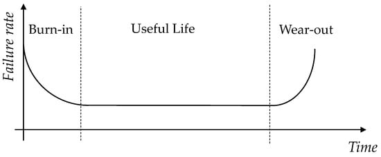
Figure 1.
Bathtub curve of a generic component during time.
According to this model, the reliability function is unitary at the beginning of the component life, i.e., R(t = 0) = 1.
The mean time to failure (MTTF) is a parameter provided for not repairable components, i.e., devices that are not repaired after their failure because their total replacement is more cost-effective and requires less time with respect to their repair. In particular, the MTTF is the expected time before a component fails. On the contrary, in case of repairable components, their repair is preferred to their complete replacement. For these devices, the mean time between failure (MTBF) quantifies the expected time between two consecutive failures.
These parameters permit to compare the reliability of systems consisting of different components. During their useful life, if repairable components fail with the same failure mode, they can be assumed to recover their total functionality after being repaired (reliability function equal to 1): in this condition, their MTBF can be assumed equivalent to their MTTF. The MTTF can be estimated with the following equation:
Under the assumption of components operating in their useful life, the MTTF can be assumed equivalent to 1/λ. The information provided by the MTTF permits to schedule the preventive maintenance of components in order to minimize their risk of failure and, thus, to improve their reliability. In case of a complex system with many identical components, the reliability for each group of identical components Ri can be calculated starting from the reliability of a single device in the following way:
where mi is the number of identical devices for each type of component and λi is the corresponding failure rate of a single device.
In case of failures, the mean time to repair (MTTR) and the mean down time (MDT) provide information regarding the rapidity of maintenance operations. In particular, the MTTR is the average time required to restore a component to its full functionality, while the MDT is the average time between a failure of a device and its restoration to normal operation [23]. Thus, in addition to MTTR, MDT includes delays due to failure detection, diagnosis, logistic, or administrative issues [24]. Figure 2 shows the difference between the MTTR and the MDT. Under correct maintenance activities, these quantities can be assumed equivalent. In order to minimize the repair time, the availability of replacement components in stock may be increased, while effective actions reducing the MDT may consist of scheduling a frequent check of devices with the highest failure rate.
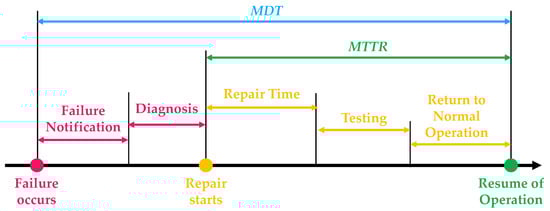
Figure 2.
Mean down time and mean time to repair of a generic component.
The availability function A represents the percentage of operation time in which the component is fully functional, i.e., the component is able to carry out its function under request. The availability of a component ranges between 0% and 100%, being the ratio between its uptime and its lifetime. In particular, the second term is the total operation time of the component, while the numerator does not include the down time due to maintenance and other sources of underperformance. The availability can be calculated starting from the MTTF and the MDT in the following way [25]:
This equation is valid if the operation time of the system is at least 4 or 5 times larger than its MDT. In this paper, the MDT and the MTTR are supposed equivalent.
3. Description of the Main Components of Full Bridge DC/AC Converters and Their Failure Rates
In the present work, the performance of three-phase full bridge DC/AC converters (voltage source inverters, VSI) is investigated [26]. They consist of the following components (in descending order of importance):
- Insulated gate bipolar transistors (IGBTs) are semiconductor switching devices with three terminals (a gate, a collector and an emitter) [27]. IGBTs permit the unidirectional current flow from the collector to the emitter (power terminals) if the voltage applied between the gate and the emitter (signal terminals to send the command) is larger than a threshold value. These devices are used for fast switching with high efficiency (switching frequency up to 50 kHz [28]) in applications like converters and power supplies. In power electronic applications, they are required to work with high currents and high voltages: in such conditions, IGBTs are preferred to bipolar junction transistors (BJTs) and metal-oxide-semiconductor field-effect transistors (MOSFETs). Indeed, high-current and high-voltage BJTs have low switching speed, while the switching frequency of MOSFETs is higher, but high-voltage and high-current MOSFETs are expensive and hard to achieve. The failure rate of IGBTs is assumed ≈0.9 × 10⁻⁶ failures per hour [20].
- Diodes, usually incorporated in the transistors as bulk components, are two-terminal semiconductor devices that permit a unidirectional flow of current [29]. In particular, they have very low resistance (obviously not constant) in the conduction direction, while their resistance is high in the other direction, in which the current cannot flow. In converter circuits, diodes are antiparallel-connected to IGBTs, in order to permit the flow of reactive power when the load is inductive. The failure rate of diodes is assumed ≈0.8 × 10⁻⁶ failures per hour [20].
- The gate driver circuit connects the power transistors with the microcontroller, regulating the switching frequency of IGBTs. Usually, the commands to the H-bridge are generated according to pulse width modulation (PWM). Its failure rate is assumed ≈1.36 × 10⁻⁶ failures per hour [15].
- Snubbers are electric circuits used to limit the voltage transients and, thus, to avoid voltage spikes. They mainly consist of capacitors, resistors and diodes, and their failure rate is ≈1 × 10⁻⁹ failures per hour [20].
- DC capacitors are two-terminal components capable of storing energy between two conducting plates, separated by a dielectric layer. In converters’ circuits, they are connected in parallel to DC source in order to stabilize and smooth their DC input voltage. This task may be achieved by connecting large electrolytic capacitors [30]; however, large capacitors increase the volume of the system and reduce its reliability. Thus, an optimal compromise between low volume of the converters and high filtering of DC voltage needs to be identified. The failure rate of DC capacitors is assumed ≈3 × 10⁻⁶ failures per hour [20].
- The DC breaker protects the converters from overcurrent phenomena. If an overload or a short circuit occur, this device interrupts the circuit, preventing possible damages to the electrical circuits. Its failure rate is assumed ≈3.3 × 10⁻⁶ failures per hour [15].
- An inductor generates an electromagnetic field when current flows through it. Generally, in power converters, an AC inductor is coupled with an AC capacitor: in this condition, they constitute a L-C filter, reducing the harmonic content of output voltage and limiting the high frequency fluctuation of current waveform. The failure rates of AC inductors and AC capacitors are assumed ≈3.8 × 10⁻⁸ failures per hour [20] and ≈8.7 × 10⁻⁷ failures per hour [15], respectively.
- Current and voltage (I-V) sensors permit to measure and store the instantaneous current and voltage. Their failure rates are, respectively, ≈5 × 10⁻⁷ and ≈5.6 × 10⁻⁷ failures per hour [20].
- The cooling circuit consists of fans that absorb heat when the operating temperature of the system exceeds the nominal value. The failure rate of the cooling fans is ≈1 × 10⁻⁶ failures per hour [20].
Figure 3 shows the components of DC/AC converters and the related power fluxes.
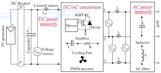
Figure 3.
Main components and corresponding power fluxes of Direct Current/Alternating Current (DC/AC) converters.
4. Description of the Case Study under Analysis
The fault tree analysis (FTA) is a diagrammatic method commonly used to improve the reliability of a system by reducing its risk of failure. This technique selects the top event of the analysis, i.e., the undesired event to avoid during operation [31]. Then, the possible combinations between the failures determining the top event are identified [32]. The top event of the FTA may consist of the failure or the breakage of a component: in the present work, the top event is the loss of output power on the AC side of the converters. Under this assumption, the system under analysis is the group of inverters (132) in the PV plant. In particular, the fault tree has a single level including the failures for the different components, i.e., the fault of any converter component determines the top event (Figure 4).
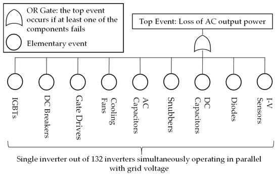
Figure 4.
Fault tree for the components of the DC/AC converters under analysis.
In this analysis, each failure is assumed independent of the others and the events are supposed not mutually exclusive, i.e., the failure of a component cannot exclude other faults. The failures are elementary events: the fault of a component does not cause another component to fail. This work does not take into account faults due to design/installation errors: each device is supposed to be properly designed and installed. Furthermore, this paper does not consider losses of PV production due to electrical mismatch, which lowers the performance of the plant and generates harmonic distortion phenomena [33]. Finally, the components of the converters are assumed repairable: in such condition, the MTTF coincides with the MTBF [34].
In the first part of this work, the reliability for the subcomponents of full bridge DC/AC converters is evaluated. In particular, 132 inverters with a total AC rated power of 46 MW in Northern Italy were analyzed using their technical datasheets and failure rates from literature. The designer of this PV system decided to undersize the converters with respect to their own PV generators (rated power = 48 MW). The ratio between the DC rated power (peak power at standard test conditions) of the PV modules and the total AC nominal power of the converters is 104%. This ratio can affect the reliability of the system. In the second part of the paper, the reliability of the components is calculated using maintenance reports and monitoring data in the years 2015–2017. Finally, the energy losses involved in the downtime and the availability are estimated for each group of components.
The converters belong to centralized configuration [35], having a rated power of 350 kW each, and they are placed in concrete cabins. The list of their specifications is presented in Table 1, and the number of components is reported for a single converter in Table 2. In particular, the number of some components (DC capacitors, diodes, snubbers, DC and AC inductors, and I-V sensors) is unknown. According to maintenance reports, they are assumed to be operating for an average time of 11 h per day.

Table 1.
Specifications of the converters.
Table 2.
Number of components for a single converter.
5. Results
In this section, the results of the reliability analysis and the repair activity, as well as the energy losses and the availability are presented. As previously written, the number of some components (DC capacitors, diodes, snubbers, DC and AC inductors, and I-V sensors) is unknown, but the maintenance reports did not detect any failure related to these devices. Moreover, according to data from literature, they are expected to work without failures for a much longer period than the years under analysis. Among these components, according to literature, electrolytic capacitors have the lowest MTTF: however, in this case, this quantity may assume values in a wide range, up to ≈15,000 h [36]. Therefore, DC capacitors may work without failing for more than 3 years (as stated in the maintenance reports).
5.1. Results Using Data from Literature
Figure 5 presents the results of the reliability analysis using data from literature: the MTTF refers to the global number of identical components in the PV plant. In particular, the IGBTs have the highest MTTF (≈1400 h), while the components with the worst performance are the gate driver circuits (MTTF ≈ 310 h). Obviously, the MTTF of the DC/AC converter (≈140 h) is lower than the single MTTF of the components, because the inverter fails if any of its components fail.
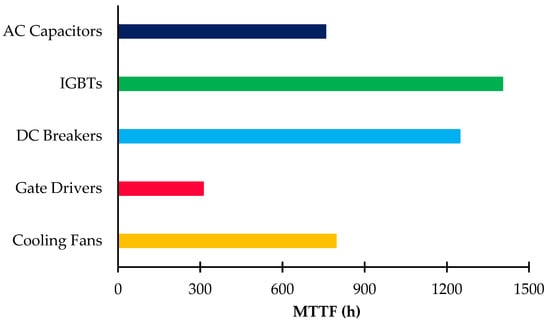
Figure 5.
Mean Time To Failure (MTTF) of the DC/AC converter components evaluated using data from literature.
In Figure 6, the profiles of the reliability function are presented.
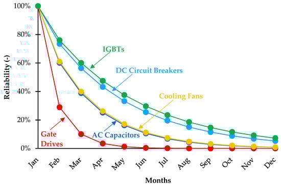
Figure 6.
Reliability function of the DC/AC converter components using data from literature (first year of operation).
After 1 year, the IGBTs, the cooling fans, the DC breakers, and the AC capacitors have a non-null reliability, i.e., their probability of being healthy after 1 year is not zero. Indeed, their reliability ranges between ≈1% (DC breakers and AC capacitors) and ≈6% (IGBTs). On the contrary, the reliability of the gate drivers is zero after a couple of months, i.e., they are very likely to require maintenance actions after that period. The reliability of the converters is zero after about 1 month.
5.2. Results Using Experimental Data from Industrial Maintenance Reports
In this section, the results of the reliability analysis using data from industrial maintenance reports are presented. Table 3 quantifies the failures of the components according to the reports: the MTTF of each group of components is obtained as the ratio between the total operation time and the corresponding number of failures recorded. In Figure 7, the MTTFs using data from maintenance reports (red bars) are compared with the results of previous subsection (yellow bars). Regarding AC capacitors, IGBTs and DC breakers, results from literature overestimate the MTTF, i.e., these components fail more frequently than expected, having real MTTF equal to ≈265, ≈415, and ≈485 h, respectively. On the contrary, the gate drivers and the cooling fans perform better than expected (MTTF ≈670 and ≈865 h, respectively); as expected, the inverter has the lowest MTTF (≈80 h).
Table 3.
Number of failures per year of the components for the 132 inverters in the PhotoVoltaic (PV) plant.
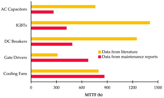
Figure 7.
MTTF obtained using data from literature (yellow) and from maintenance reports (red).
The deviations between the results using failure rates from literature and data from maintenance reports may be very high, up to several thousand hours. However, the failure rates from literature are average values taken from experimental datasets at international level. Obviously, these data may refer to very different PV plants from the system under analysis. In such condition, high deviations around the mean value may occur, and it is preferred to compare the results using another parameter rather than the MTTF. This new quantity can be evaluated for the components and the DC/AC converters as well, being the ratio between two terms. The numerator consists of the MTTF deviations (in terms of hours) between values from literature and from maintenance reports, while the denominator is the number of operation hours. In the present paper, this parameter is reasonably low (≈8%) for the components with the lowest MTTF from the reports (IGBTs): thus, the agreement of the model used to estimate the reliability of the system starting from literature data with the reports is confirmed. For the other groups of components, this parameter is much lower, being ≈0.6% for the cooling fans and ≈0.5% for the converters.
The MTTR of each component group is evaluated from maintenance reports as the ratio between the total repair time and the number of maintenance activities for each group. The components requiring the lowest time to be repaired are the cooling fans (≈2 h) and the DC breakers (≈3 h). On the contrary, the highest MTTR is related to the IGBTs (≈95 h), which is more than four times higher than the other components (the highest value is ≈19 h for gate drivers). For this reason, the maintenance operations regarding IGBTs were analyzed in detail, and many delays in the supply of spare components, up to 40 days, were identified. This issue occurred mainly in the first 2 years of the analysis (2015 and 2016), determining a MTTR of 175 and 90 h, respectively. On the contrary, in 2017, these problems were solved, and the IGBTs were repaired without delays in a much lower average time (MTTR≈16 h). Therefore, the data of the years 2015–2016 regarding the repair of IGBTs were excluded from this analysis; the MTTR values are reported in Figure 8. The MTTR of the DC/AC converters amounts to ≈9 h.
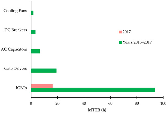
Figure 8.
Mean Time To Repair (MTTR) of the groups of components.
The energy losses involved in the downtime durations confirm this behavior. In particular, they were estimated starting from the information provided in the reports (the AC energy generated by the single inverters in time intervals of 15 min). In case of failures, the associated energy losses, for each faulty DC/AC converter, were estimated as the difference between the energy produced by another converter in normal operation and the energy generated by the faulty device in the reports. The converters of the 48 MW system are identical, and the connected PV generators have the same orientation and inclination, without shadowing phenomena. Therefore, in case of faults, the first quantity was assumed as the average energy generated by the other inverters, working properly. The total energy losses in the years 2015–2017 are ≈−0.2%.
However, huge differences occur in the 3 years: in fact, the energy losses in 2015 (≈−0.3%) and 2016 (≈−0.2%) are more than four times higher than the corresponding quantity in 2017 (≈−0.06%). This is due to the delayed maintenance that occurred in 2015 and 2016 regarding IGBTs. Finally, the availability ranges between ≈96% (IGBTs) and 100% (cooling fans), determining a converter availability of ≈90% (Table 4).
Table 4.
Availability for the components of the DC/AC converters.
6. Conclusions
The present work performed a reliability analysis and the repair activity for the components of 132 full bridge inverters with rated power of 350 kW each. Moreover, a second reliability analysis was performed using data from industrial maintenance reports. The results of the two analyses were compared in order to investigate the agreement of the model from literature with respect to the reports. In the first part of the work, reliability results were obtained using failure rates from literature, while in the second part, industrial maintenance reports were analyzed to evaluate the MTTF and the MTTR for the global number of components in the PV plant. According to the reports, the components with the highest MTTF (≈865 h) are the cooling fans, while the AC capacitors have the worst performance (MTTF≈265 h). The MTTF of the IGBTs is ≈415 h, and the overall MTTF of DC/AC converters is ≈80 h.
According to the results using failure rates from literature, the components with the worst performance are the gate drivers (MTTF≈310 h). However, the industrial reports show that these components perform better than expected (MTTF≈670 h). As a consequence, operators may schedule a less restrictive maintenance on gate drivers. On the contrary, designers should invest mainly on improving the reliability of other components. Actually, according to the reports, the MTTF of AC capacitors, IGBTs and DC breakers is less than 40% of the corresponding MTTF estimated using data from literature. Thus, improving the reliability of these components is crucial to increase the reliability and availability of the entire converter.
In addition, the reliability of the converters may be affected by the ratio between the DC and AC rated powers of the PV system. This ratio is, generally, higher than 100% [37] for PV plants actually in operation in order to maximize their power generation at low/intermediate irradiance. In this case, converters may work more frequently close to their rated power: however, this condition increases the thermal stress of their components, which may become more subject to failures. In this work, the ratio between the rated power of PV generators and the AC nominal powers of the 132 converters is ≈104%. Thus, the converters are slightly undersized with respect to PV generators, but to improve the reliability of the system, it may be advisable to equalize the two parameters, especially in sunny and windy sites (as in the Mediterranean area). Nevertheless, values lower than 100% are favorable for the reliability but increase the installation costs.
Regarding the MTTR, the highest value is for the IGBTs, while the cooling fans have the best performance, being repaired within an average time of 2 h. However, the MTTR of IGBTs is more than four times higher than the other components: thus, the maintenance performance of IGBTs was further investigated by analyzing the reports in detail. Indeed, many delays in the supply of spare parts for these components (up to 40 days) are identified for the first 2 years of the analysis (2015 and 2016). These issues are not detected in 2017: the IGBTs are repaired within an average time of 16 h. Thus, the data of the years 2015–2016 regarding the repair of IGBTs were excluded from this analysis, and the MTTR of the DC/AC converters is ≈9h. The energy losses due to the absence of operation during the downtime confirm this behavior, being more than four times higher in 2015 (≈−0.3%) and in 2016 (≈−0.2%) with respect to 2017 (≈−0.06%). Finally, the availability for the different groups of components is higher than 97%, with an overall value of 90% for the inverters.
Author Contributions
Conceptualization, F.S.; methodology, F.S., G.C., G.M.; writing—original draft preparation, A.A., G.C., G.M.; writing—review and editing, F.S., A.A., G.C., A.C., G.M.; visualization, F.S., A.A., G.C., A.C., G.M.; supervision, F.S.. All authors have read and agreed to the published version of the manuscript.
Funding
This research received no external funding.
Data Availability Statement
Data are not available on a publicly accessible repository and they cannot be shared under request.
Conflicts of Interest
The authors declare no conflict of interest.
References
- Spertino, F.; Fichera, S.; Ciocia, A.; Malgaroli, G.; Di Leo, P.; Ratclif, A. Toward the complete self-sufficiency of an NZEBS microgrid by photovoltaic generators and heat pumps: Methods and applications. IEEE Trans. Ind. Appl. 2019, 55, 7028–7040. [Google Scholar] [CrossRef]
- Di Leo, P.; Spertino, F.; Fichera, S.; Malgaroli, G.; Ratclif, A. Improvement of self-sufficiency for an innovative nearly zero energy building by photovoltaic generators. In Proceedings of the 2019 IEEE Milan PowerTech, Milan, Italy, 23–27 June 2019; pp. 1–6. [Google Scholar] [CrossRef]
- Ciocia, A.; Di Leo, P.; Fichera, S.; Giordano, F.; Malgaroli, G.; Spertino, F. A novel procedure to adjust the equivalent circuit parameters of photovoltaic modules under shading. In Proceedings of the 2020 International Symposium on Power Electronics, Electrical Drives, Automation and Motion (SPEEDAM), Sorrento, Italy, 24–26 June 2020; pp. 711–715. [Google Scholar] [CrossRef]
- Spertino, F.; Chiodo, E.; Ciocia, A.; Malgaroli, G.; Ratclif, A. Maintenance Activity, Reliability Analysis and Related Energy Losses in Five Operating Photovoltaic Plants. In Proceedings of the 2019 IEEE International Conference on Environment and Electrical Engineering and 2019 IEEE Industrial and Commercial Power Systems Europe (EEEIC/I&CPS Europe), Genova, Italy, 11–14 June 2019; pp. 1–6. [Google Scholar] [CrossRef]
- Spertino, F.; Chiodo, E.; Ciocia, A.; Malgaroli, G.; Ratclif, A. Maintenance Activity, Reliability, Availability, and Related Energy Losses in Ten Operating Photovoltaic Systems up to 1.8 MW. IEEE Trans. Ind. Appl. 2021, 57, 83–93. [Google Scholar] [CrossRef]
- Humada, A.M.; Darweesh, S.Y.; Mohammed, K.G.; Kamil, M.; Mohammed, S.F.; Kasim, N.K.; Tahseen, T.A.; Awad, O.I.; Mekhilef, S. Modeling of PV system and parameter extraction based on experimental data: Review and investigation. Sol. Energy 2020, 199, 742–760. [Google Scholar] [CrossRef]
- Spertino, F.; Ahmad, J.; Chicco, G.; Ciocia, A.; Di Leo, P. Matching between electric generation and load: Hybrid PV-wind system and tertiary-sector users. In Proceedings of the 2015 50th International Universities Power Engineering Conference (UPEC), Stoke on Trent, UK, 1–4 September 2015; pp. 1–6. [Google Scholar] [CrossRef]
- El-Metwally, M.; EL-Shimy, M.; Elshahed, M.; Sayed, A. Detailed Analyses of the Failure and Repair Rates of Wind and Solar- PV Systems for RAM Assessment. In Proceedings of the 11th International Conference on Electrical Engineering (ICEENG), Cairo, Egypt, 3–5 April 2018; Volume 11, pp. 1–16. [Google Scholar] [CrossRef]
- Yang, Y.; Wang, H.; Sangwongwanich, A.; Blaabjerg, F. 45-Design for Reliability of Power Electronic Systems. In Power Electronics Handbook; Elsevier Science & Technology: Amsterdam, The Netherlands, 2018; pp. 1423–1440. [Google Scholar]
- Koutroulis, E.; Blaabjerg, F. Design optimization of transformerless grid-connected PV inverters including reliability. IEEE Trans. Power Electron. 2013, 28, 325–335. [Google Scholar] [CrossRef]
- Umarani, D.; Seyezhai, R. Investigation of Reliability Aspects of Photovoltaic Quasi Z-Source Inverter. In Proceedings of the 2018 IEEE International Conference on Power Electronics, Drives and Energy Systems (PEDES), Chennai, India, 18–21 December 2018; pp. 1–5. [Google Scholar] [CrossRef]
- Ahadi, A.; Ghadimi, N.; Mirabbasi, D. Reliability assessment for components of large scale photovoltaic systems. J. Power Sources 2014, 264, 211–219. [Google Scholar] [CrossRef]
- Shi, X.; Bazzi, A.M. Solar photovoltaic power electronic systems: Design for reliability approach. In Proceedings of the 2015 17th European Conference on Power Electronics and Applications (EPE’15 ECCE-Europe), Geneva, Switzerland, 8–10 September 2015; pp. 1–8. [Google Scholar] [CrossRef]
- Ristow, A.; Begović, M.; Pregelj, A.; Rohatgi, A. Development of a methodology for improving photovoltaic inverter reliability. IEEE Trans. Ind. Electron. 2008, 55, 2581–2592. [Google Scholar] [CrossRef]
- Ma, Z.J.; Thomas, S. Reliability and maintainability in photovoltaic inverter design. In Proceedings of the 2011 Proceedings—Annual Reliability and Maintainability Symposium, Lake Buena Vista, FL, USA, 24–27 January 2011; pp. 1–5. [Google Scholar] [CrossRef]
- Department of Defense of the USA. Reliability Prediction of Electronic Equipment. In Military Handbook MIL-HDBK-217F; Department of Defense of the USA: Washington, DC, USA, 1991; MIL-HDBK-217F (NOTICE 1). [Google Scholar]
- Song, Y.; Wang, B. Survey on reliability of power electronic systems. IEEE Trans. Power Electron. 2013, 28, 591–604. [Google Scholar] [CrossRef]
- Rausand, M.; Hoyland, A. System Reliability Theory: Models, Statistical Methods, and Applications; John Wiley & Sons: Hoboken, NJ, USA, 2004. [Google Scholar]
- Obeidat, F.; Shuttleworth, R. Reliability prediction of PV inverters based on MIL-HDBK-217F N2. In Proceedings of the 2015 IEEE 42nd Photovoltaic Specialist Conference (PVSC), New Orleans, LA, USA, 14–19 June 2015; pp. 1–6. [Google Scholar] [CrossRef]
- Yu, X.; Khambadkone, A.M. Reliability analysis and cost optimization of parallel-inverter system. IEEE Trans. Ind. Electron. 2012, 59, 3881–3889. [Google Scholar] [CrossRef]
- Cooper, M. Observations on component infant mortality and burn-in effectiveness. IEEE Trans. Components Packag. Technol. 2008, 31, 914–916. [Google Scholar] [CrossRef]
- Alvarez-Alvarado, M.S.; Jayaweera, D. Bathtub curve as a Markovian process to describe the reliability of repairable components. IET Gener. Transm. Distrib. 2018, 12, 5683–5689. [Google Scholar] [CrossRef]
- Baschel, S.; Koubli, E.; Roy, J.; Gottschalg, R. Impact of component reliability on large scale photovoltaic systems’ performance. Energies 2018, 11, 1579. [Google Scholar] [CrossRef]
- Selvik, J.T.; Ford, E.P. Down Time Terms and Information Used for Assessment of Equipment Reliability and Maintenance Performance. In System Reliability; InTech Open: Rijeka, Croatia, 2017. [Google Scholar] [CrossRef]
- Elsayed, E.A. Reliability Engineering; Addison Wesley, Reading: Boston, MA, USA, 1996. [Google Scholar]
- Gao, D.; Sun, K. 16-DC–AC inverters. In Electric Renewable Energy Systems; Academic Press: Cambridge, MA, USA, 2016; pp. 354–381. [Google Scholar]
- Abedinpour, S.; Shenai, K. 5-Insulated Gate Bipolar Transistor. In Power Electronics Handbook, 2nd ed.; Elsevier: Amsterdam, The Netherlands, 2007; pp. 71–88. [Google Scholar]
- IGBT Technologies and Applications Overview: How and When to Use an IGBT. Available online: https://www.onsemi.com/pub/Collateral/TND6235-D.PDF (accessed on 28 January 2021).
- Ciocia, A.; Di Leo, P.; Fichera, S.; Malgaroli, G.; Russo, A.; Spertino, F.; Tzanova, S.; Dalanbayar, B. Innovative Laboratories for Teaching on Photovoltaic Generation in Higher Education. In Proceedings of the 2020 XXIX International Scientific Conference Electronics (ET), Sozopol, Bulgaria, 16–18 September 2020; pp. 1–4. [Google Scholar] [CrossRef]
- Vujacic, M.; Hammami, M.; Srndovic, M.; Grandi, G. Analysis of dc-link voltage switching ripple in three-phase PWM inverters. Energies 2018, 11, 471. [Google Scholar] [CrossRef]
- Golnas, A. PV system reliability: An operator’s perspective. IEEE J. Photovolt. 2013, 3, 416–421. [Google Scholar] [CrossRef]
- Kritzinger, D. 4-Fault Tree Analysis. In Aircraft System Safety; Elsevier Science & Technology: Amsterdam, The Netherlands, 2017; pp. 59–99. [Google Scholar]
- Chicco, G.; Corona, F.; Porumb, R.; Spertino, F. Experimental indicators of current unbalance in building-integrated photovoltaic systems. IEEE J. Photovolt. 2014, 4, 924–934. [Google Scholar] [CrossRef]
- Zini, G.; Mangeant, C.; Merten, J. Reliability of large-scale grid-connected photovoltaic systems. Renew. Energy 2011, 36, 2334–2340. [Google Scholar] [CrossRef]
- Spertino, F.; Chicco, G.; Ciocia, A.; Malgaroli, G.; Mazza, A.; Russo, A. Harmonic distortion and unbalance analysis in multi-inverter photovoltaic systems. In Proceedings of the 2018 International Symposium on Power Electronics, Electrical Drives, Automation and Motion (SPEEDAM), Amalfi, Italy, 20–22 June 2018; pp. 1031–1036. [Google Scholar] [CrossRef]
- Flicker, J.D. Capacitor Reliability in Photovoltaic Inverters; Sandia National Laboratories: Albuquerque, NM, USA, 2015. [Google Scholar]
- Oversizing of SolarEdge Inverters, Technical Note—SolarEdge. Available online: https://www.solaredge.com/sites/default/files/inverter_dc_oversizing_guide.pdf (accessed on 16 February 2021).
Publisher’s Note: MDPI stays neutral with regard to jurisdictional claims in published maps and institutional affiliations. |
© 2021 by the authors. Licensee MDPI, Basel, Switzerland. This article is an open access article distributed under the terms and conditions of the Creative Commons Attribution (CC BY) license (http://creativecommons.org/licenses/by/4.0/).