Abstract
Today, the world’s electricity consumption is growing rapidly, and therefore energy demands are also increasing. In the past few decades, various measures have been taken to improve equipment and system design to increase production and transmission efficiency and reduce power consumption. This article proposes a novel Internet of Things (IoT)-based temperature control power extender with two working modes of cooling and heating to solve power shortages. The power is turned on or off accurately and in a timely manner through a temperature-sensing element, thereby avoiding unnecessary power consumption to achieve the goal of energy-saving. This can directly power on or off the power extender through the Internet. It can also use a 2.4G Wi-Fi wireless transmission to transmit, for example, real-time temperature information, the switch status and the master–slave mode. Related data can be controlled, collected and uploaded to the cloud. Each proposed power extender’s temperature setting in a large-scale field can be set uniformly, and no staff is wasted to set the temperature separately. Taking a general industrial electric fan as an example, if it is changed to drive with this temperature control extension cable, and assuming that the industrial electric fan is activated for 900 s per hour, its power-saving rate is 74.75%.
1. Introduction
Global warming is becoming more and more serious, and climate abnormalities worldwide occur one after another. After the Kyoto Protocol to curb global greenhouse gas emissions comes into effect, energy technology innovation and energy conservation will become effective strategies for reducing carbon dioxide. Due to the gradual expansion of global warming and the rapid changes in the ecological environment, many different ecological crises have begun to occur worldwide. Therefore, all government organizations and non-governmental organizations attach great importance to such an issue [1].
Nowadays, the world’s residential electricity consumption is growing rapidly. People are more and more interested in more efficient devices for such a large amount of energy, especially after doubling oil prices led to an increase in electricity rates [2]. Population growth has brought about the problem of a lack of natural resources. Artificial resources such as electricity cannot cope with rapid population growth. In the past few decades, various measures have been taken to improve the equipment and system design to increase production and transmission efficiency and reduce power consumption [3].
Many smart machines and pieces of equipment are dedicated to reducing power consumption. Still, as long as devices and equipment are related to the term smart, their prices are usually high, and existing machines and gear do not have smart power-saving features, such as smart Internet of Things (IoT) sockets. As a result, old appliances and equipment can monitor their energy consumption through the socket, and they can also be controlled remotely through a mobile phone. As such, if the old machines and equipment are connected to the smart socket, they can instantly become intelligent machines or equipment.
Recently, some related works on smart sockets have been discussed [4,5,6,7,8,9,10]. Musleh et al. [4] established a master–slave architecture smart socket. The socket used voltage- and current-sensing circuits to measure the power of the smart socket. The master part connected to the Internet through Wi-Fi wireless communication. The slave part communicated through the Zigbee wireless communication protocol in the mesh configuration. However, for sockets with multiple jacks, the entire circuit will have to be repeated many times, which will greatly increase the costs.
Thongkhao et al. [5] proposed a single-socket solution which used Wi-Fi for communication. Patil et al. [6] developed a power socket controlled by an Android application, which communicated with the power socket via general packet radio service (GPRS). Furthermore, for the relays connected to the device, the ARM7 controller was also connected to various sensors, such as the temperature, gas, light dependent resistor (LDR) and passive infrared sensor (PIR) sensors. Since their model used GPRS, there would be additional communication costs every month, and the price would increase depending on the number of sockets installed. In [7], the Bluetooth low energy (BLE)-based smart plug was a single socket solution (one wireless module per socket) in which BLE was used for socket communication, and a smartphone controlled the socket.
Lin et al. [8] proposed a smart socket, called the MorSocket, which was used for intelligent campus deployment. This system allowed users to use a control page to control multiple individual sockets. Smartphones could manipulate and control the sockets via Wi-Fi or Bluetooth. These sockets shared the same wireless communication module, so the hardware cost of the MorSocket was lower than a single-socket solution.
Ramavarapu et al. [9] provided a useful example for the realization of smart power sockets; that is, the Intel Edison development board controlled their product: Belkin WeMo stylish Plus with Wi-Fi. Real-time pricing information was used to activate or deactivate the socket’s power. The power socket could be turned on during the low-price period (usually used for a high load). This method could achieve the purpose of cost-saving. A similar analysis for energy management was also provided in [10].
Nurelmadina et al. [11] reviewed the emerging IoT technologies for industrial IoT applications. The emerging IoT technologies usually used wireless networks to propagate commands and receive responses [12]. However, if a large number of nodes responded via wireless networks simultaneously, serious conflicts could occur. This phenomenon is well known as the acknowledgement (ACK) or feedback implosion problem [13]. Besides that, if the node responded immediately after receiving the command, the response would also interfere with the command distribution. On the other hand, if the node responded slowly (for example, waiting for a while for the command distribution to complete), the response would be delayed. Thus, this would increase the overall delay of the system.
Many existing studies are trying to alleviate congestion in low-power wireless networks to improve reliability and latencies. However, most of them only focus on one side of the problem. Some only try to improve the downward command propagation phase [14,15,16,17,18,19]. Some focus on improving the upward response collection phase [20,21,22,23,24,25]. Since the command phase, data packet and response phase data packet will conflict by themselves and conflict with each other, focusing on one side is not enough to provide adequate performance for actual IoT applications. As a result, they must be considered jointly [12]. Hao and Zhang [26] analyzed media access control (MAC) performance for reliable power-line communication networks with automatic repeat request (ARQ) schemes. Saban et al. [27] developed a sensor node-based network for remote moisture measurement in timber based on Bluetooth low energy (BLE) and a web-based monitoring system. Other extender applications can be found in [28,29,30,31,32,33,34,35,36,37,38,39,40,41].
This article proposes a novel master–slave expandable modular IoT-based temperature control extensor. The proposed extensor provides two working modes of cooling and heating through a temperature-sensing element to turn on or off the power accurately and in a timely manner, thereby avoiding unnecessary power consumption. Besides that, the data of real-time temperature information, the switch status and the master–slave mode control can be collected and uploaded to the cloud through Wi-Fi wireless transmission. The terminal device can perform manual, semi-automatic and fully automatic parameter setting and can achieve energy-saving in multiple applications. Therefore, each function’s research and planning are a modular design. The functional modules are connected in series through the connecting board, thereby achieving low costs and miniaturization advantages.
2. Preliminary
The primary purpose of this work is energy saving. In many areas, the weather is too hot in summer. People usually use air conditioners to lower indoor temperatures. However, the air conditioner consumes a lot of electricity, so many people only turn on the air conditioner. After 3 h, the air conditioner will be turned off (using a timer function). Nevertheless, the indoor temperature will slowly rise at this time, and it may take less than 30 min for people to wake up from high temperatures. Hence, they must get up and turn on the electric fan to dissipate the heat, interrupting sleep, and over a long time, this leads to low sleep quality. At this point, if we use our work to assist with controlling indoor temperatures, we can significantly improve this situation. When the temperature rises above the set temperature in this work’s cooling mode, the temperature control extension cord will start to supply power to the socket connected to the cooling method. Currently, the device (such as an electric fan) begins to cool down the temperature. When the temperature is too low, the temperature control extension cord will stop the power supply to avoid wasting power.
In this way, people can use the air conditioner and low-power electric fans—instead of using the power-consuming air conditioner for cooling all night—if the air conditioner is turned on for 2–3 h. First, we can use the temperature control power extender to turn on the electric fan to dissipate heat, as shown in Figure 1.
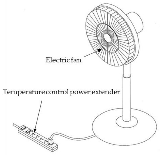
Figure 1.
Scenario of an electric fan connected to the temperature control extensor.
It can quickly achieve the indoor cooling and energy-saving objectives. Hence, we can also use the proposed temperature control extensor to turn on the electric fan while turning on the air conditioner and reduce the indoor temperature at the same time. Furthermore, some experts have found that every one degree decrease in the set temperature will consume about 2–3% of the electricity. Therefore, it is recommended to use low-power electric fans when using air conditioners. When the indoor temperature reaches a sufficient cooling level, the temperature control extensor will automatically turn off the electric fan, which will avoid improper power wasting.
This work can also be used to facilitate the breeding of livestock. For example, general pig farms have very high requirements for temperature control. Heat stress is prone to occur when the ambient temperature exceeds 33 °C and the duration of this temperature is long. Given this response, if ventilation and cooling measures are not taken to improve the environmental temperature and humidity, the pig’s health will be compromised, which will affect the efficiency of breeding. Therefore, in the hot summer, pig farms face high temperatures, high humidity and unfavorable climates. However, the farm cannot install air conditioning to control the temperature due to the consideration of electricity costs. Generally, only large industrial fans are used to cool down these facilities. When using large industrial fans to cool down temperatures, the impact on the electricity bill is also very considerable.
Moreover, industrial fans can only cool down temperatures. If the temperature drops significantly in the middle of the night, it will be too cold and cause some pigs discomfort. At this time, if the industrial fan is connected to the temperature control extension line, when the temperature of the farm is too high, the industrial fan will automatically start. When the temperature is too low, the industrial fan will automatically turn off.
This work can be used to cool down residential environments and livestock breeding facilities and be used to cool outdoor equipment. Benoit-Cattin et al. [42] evaluated the effect of long-term high temperatures on a CPU-based edge device’s performance. The experiment proved heat dissipation. It greatly helped to improve the CPU-based edge device’s performance. Therefore, if the temperature control extensor is used to cool outdoor equipment, then it is an excellent energy-saving choice. Usually, when the sun out completely, the cooling demand is very high. The night temperature is lower, and no additional cooling is required.
Conversely, this work can also provide a heating mode when the temperature drops below the set temperature. The proposed IoT-based temperature control extensor starts to supply power to the heating device connected to the socket (such as an electric heater). When the temperature is too high, the proposed IoT-based temperature control extensor will stop supplying power. When the elderly or children are in a cold winter, they need the heating mode of the proposed IoT-based temperature control extensor, and this function is also very much required when raising chickens or pigs.
In summary, the proposed IoT-based temperature control power extender mainly provides the following contributions:
- The power is turned on or off accurately and in a timely manner through a temperature-sensing element, thereby avoiding unnecessary power consumption and achieving the purpose of energy-saving;
- When the proposed power extenders are used in large-scale farms, the commands are transmitted to other slave power extenders through Wi-Fi 2.4G wireless transmission, saving on setting staffing;
- Old machines and equipment can have smart functions through the proposed power extender, and their switches can be controlled remotely through a mobile device.
3. The Proposed IoT-Based Temperature Control Power Extender
The proposed IoT-based temperature control power extender can accurately turn on or off the power supply at the right time through a temperature-sensing element. It can also directly turn on or off the power extender through the Internet. A Wi-Fi wireless transmission module uniformly sets each extender’s temperature setting in a large field.
3.1. System Process and Architecture
Figure 2 shows a flowchart of the system process. Figure 3 shows the system architecture. As shown in Figure 2, the system first establishes a connection with the cloud server. If there is no connection, the system will repeatedly try to establish a relationship. After a connection is established, the system will wait for a command from the application and turn on or off the proposed power extender’s power supply, according to the command’s content. Then, the system will turn on or off or set the proposed power extender’s heating or cooling mode, high temperature value and low temperature value. Then, the system checks whether the connection continues and repeats the whole process.
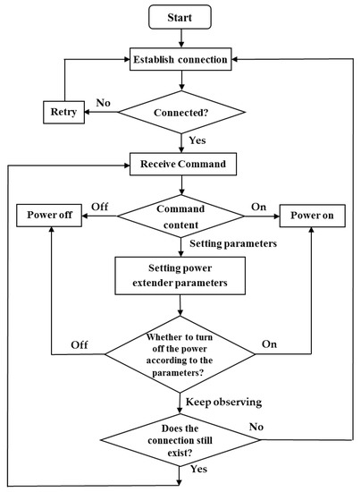
Figure 2.
Flowchart of the system process.
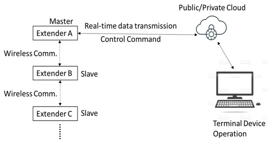
Figure 3.
System architecture.
The proposed IoT-based temperature control power extender can upload real-time temperature information, as well as the switch status and master–slave mode control. These related data can be collected in the cloud through Wi-Fi wireless transmission. The terminal device can perform under manual, semi-automatic or fully automatic parameter settings. The terminal device can be a mobile phone, a tablet or a computer. When master power extender A receives the command information from the public or private cloud server, it will immediately forward the command to other slave power extenders via Wi-Fi wireless transmission.
3.2. Hardware Implementation
Figure 4 shows the hardware block diagram of the proposed IoT-based temperature control power extender. The power supply module is a 110 V/220 V universal voltage. The microcontroller unit (MCU), according to the set temperature information and the current temperature, sends commands to the control circuit to determine whether the extender should be powered to the output terminal. The rules of deciding whether to supply power are shown in Table 1. The communication module is a Wi-Fi 2.4G wireless transmission module responsible for data transmission with the cloud and transmission between extenders, as shown in Figure 4.
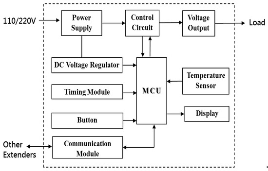
Figure 4.
Hardware block diagram of the proposed Internet of Things (IoT)-based temperature control extender.

Table 1.
Power supply rules for the cooling and heating modes.
In this article, the high temperature value is marked as the Max, and the low temperature value is marked as the Min. When the temperature rises above the set high temperature value in cooling mode, the temperature control extension cord will supply power to the cooling device connected to the socket. At this time, the target object will start to cool down. When the temperature is lower than the set low temperature value, the temperature control extension cord will stop supplying power. Conversely, when the temperature drops below the set low temperature value in heating mode, the temperature control extension cord will supply power to the heating device connected to the socket. At this time, the target will start to raise the temperature. When the high temperature is higher than the set value, the temperature control extension cord will stop supplying power. A photograph of the hardware prototype of this work can be seen in Figure 5.
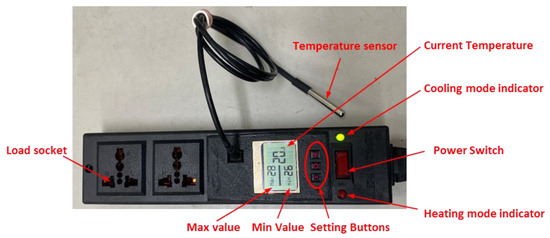
Figure 5.
Photograph of the hardware prototype of the proposed extender.
The setting buttons can set the extender’s heating or cooling mode, high temperature value, low temperature value and other information. The temperature setting button increases or decreases the temperature. Taking Figure 6 as an example, it is currently set to cooling mode, where the high temperature value is 26 °C, the low temperature value is 24 °C and the current temperature is 20.6 °C. If the temperature rises to 26 °C, the proposed extender will supply power to the load (such as an electric fan) when the temperature drops to 24 °C, and the proposed extender’s sockets stop supplying power (power off).
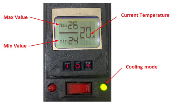
Figure 6.
Cooling mode example. It is currently set to cooling mode. The high temperature value is 26 °C, the low temperature value is 24 °C and the current temperature is 20.6 °C.
Figure 7 demonstrates an example of the heating mode, where the high temperature value is 24 °C, the low temperature value is 21 °C and the current temperature is 20.7 °C. If the temperature is lower than 21 °C (currently lower than 21 °C), the sockets of the proposed extender will supply power to the load (such as an electric heater), and when the temperature rises to 24 °C, the sockets of the proposed extender will stop supplying power (power off). In addition to setting these parameters through the setting buttons of the proposed IoT-based temperature control extender, the proposed extender can also be set via the mobile device application, as shown in Figure 8.
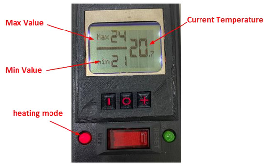
Figure 7.
Heating mode example. It is currently set to heating mode, where the high temperature value is 24 °C, the low temperature value is 21 °C and the current temperature is 20.7 °C.
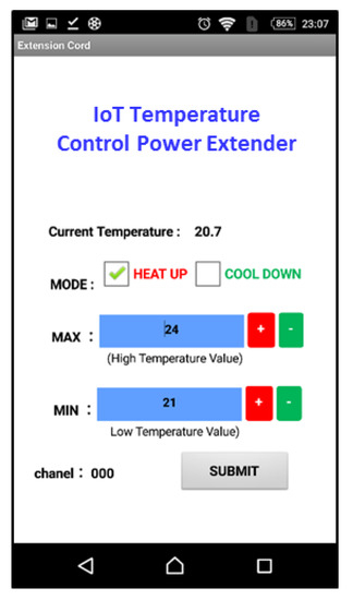
Figure 8.
Screen of the mobile device application. The parameters of the proposed extender can also be set via the mobile device application.
In addition to the heating or cooling modes, high temperature value and low temperature value of the proposed extender, we can also see the channel value of the proposed extender. This function is designed for large application fields because the number of proposed extenders may be as many as hundreds in a large application field. It is a vast project to establish such a large number of extenders. Therefore, the proposed extender with the same channel value can be set to the same parameter value simultaneously, which can save a lot of effort. For example, suppose the master extender in Figure 9 is set to 000 (i.e., the dip switch is set to 000). In that case, the set parameters can be transferred to other channels through Wi-Fi wireless transmission and assigned to the slave extender of 000 for the slave sockets of different channels. As a result, this setting cannot be received.
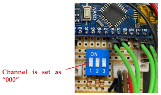
Figure 9.
Channel setting example. The channel of the master extender is set to 000.
Finally, the adopted electronic components and their specifications for this work are shown in Table 2. The relay module is a 5 V/10 A two-channel relay board. Each channel requires approximately 15–20 mA of driver current and can be safely connected to loads with up to 250 V and 10 A AC voltage and a 30 V and 10 A DC voltage. The relay is very useful in most control applications because it can directly control the relay by the 3.3 V or 5 V signal of the PIC, DSP, AVR, Arduino or other microcontrollers.

Table 2.
Adopted electronic components and their specifications in this work.
In this article, the communication transmission adopts the message queuing telemetry transport (MQTT) protocol architecture [43]. Hence, the system can synchronize the time with the central server every minute, avoiding the related problems caused by an unsynchronized time and data delays as follows:
- We use the finite element machine architecture to write programs, and the device will automatically ignore it to avoid errors when assisting with false data injection [44];
- We use the timestamp as the judgment of data approval, so the same timestamp will only approve one piece of data. Hence, data with errors due to delay can be ignored;
- Because of the solution to the first two problems, system resources can be prevented from being exhausted due to heavy occupation.
4. Energy-Saving Analysis and Discussion
4.1. Energy Comsunption Calculation
When the temperature of the environment and the electrical appliance power are different, the proposed extender’s calculated energy-saving effect could be different. Even in the same environment with the same electrical appliances, the Max and Min values are set by the proposed extender. When the value is different, the energy-saving effect obtained is different. For example, in a livestock farm, the temperature of a particular day falls between 28 °C and 23 °C. If the Max value is set to 27 °C, the Min is set to 26 °C and the energy-saving effect obtained by the other set of Max values is set to 28 °C, the Min value is set to 27 °C, which is absolutely different.
It is more complicated to calculate electrical appliances’ power consumption when connected to the proposed extender. Unlike ordinary electrical appliances, which consume pure power, the factors that affect power consumption include the temperature setting, ambient temperature and electrical appliance type, among other factors. For the convenience of deriving the formula, we take the industrial electric fan of a livestock farm as an example. Moreover, the calculation method of electric energy consumption is referred to in [1]. The electric energy consumed is calculated for every hour of the industrial electric fan using the proposed extender and the unused extender. Industrial electric fans are used to calculate the energy-saving rate (ESR). Figure 10 shows the hourly power consumption curve of an industrial fan with the proposed extender. In other words, Figure 10 illustrates how to calculate an industrial fan’s hourly power consumption with the proposed extender.
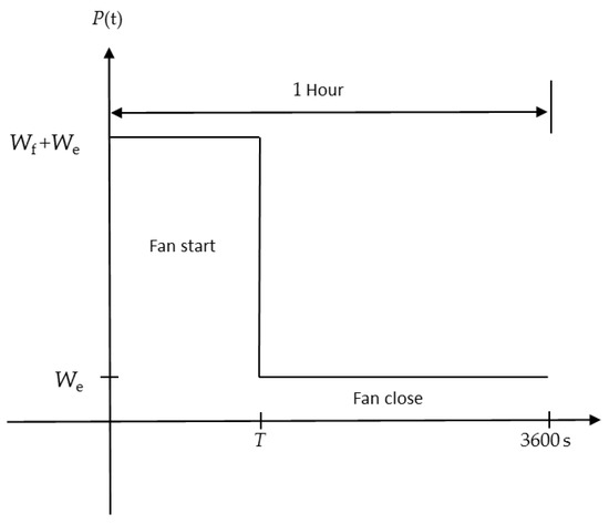
Figure 10.
Hourly power consumption curve.
Please note that P(t) is the hourly power consumption change of the industrial electric fans with recombined temperature control extension cords. The meanings of the other parameters are as follows: T is the cumulative number of seconds to start an industrial fan per hour; Wf is the power when the industrial electric fan starts, with the power consumption of the general industrial electric fan mostly falling between 150 W and 400 W; and We is the power of the proposed extender. The actual measured power of the prototype of the proposed extender is 0.7 W.
As shown in Figure 10, the industrial electric fan using the proposed extender has T seconds per hour to maintain the starting state (the cumulative total of T seconds is the starting state, not 0-T seconds) of 3600-T seconds. This is to maintain the closed state and calculate the electric energy Eph consumed by the industrial fan per hour by calculating the area:
Besides that, we assume that in the livestock farm, the industrial fans are turned on 24 h a day and a total of 24 × 365 = 8760 h in a year. Therefore, the annual electric energy Epy of each industrial fan is
Compared with industrial fans that do not use the proposed extender cords, because industrial fans are always in the starting state, the electric energy consumed by each fan per year is Fpy = (Wf/1000) × 8760 = 8.76 × Wf kw h. Thus, we can calculate the ESR and the annual saving of each fan if the general industrial electric fan in the livestock farm is changed to an industrial electric fan using the proposed extender. The annual electricity consumption Dpy, the annual cost Mpy (assuming 4 NT$ per kilowatt-hour of electricity) and the annual carbon emission reduction Cpy are calculated as follows (each kilowatt-hour (kw h) can generate 0.623 kgCO2e carbon emissions):
ESR = ((Wf/1000) − Eph)/(Wf/1000) × 100% = (Wf − 1000 × Eph)/Wf
Dpy = Fpy − Epy = 8.76 × (Wf − 1000 × Eph) kw h
Mpy = (Fpy − Epy) kw h × 4 NT dollar / kw h
Cpy = (Fpy − Epy) kw h × 0.623 kgCO2e / kw h
4.2. ESR Calculation
Since the ESR of industrial electric fans using the proposed extender is closely related to the average hourly industrial electric fan’s cumulative start-up seconds T, this subsection discusses the relationship between the ESR and the average hourly start-up seconds T of an industrial electric fan. Moreover, we calculate the maximum and minimum ESR.
First, from Equation (3), it can be seen that the ESR is inversely proportional to the electric energy consumed by an industrial fan per hour Eph using the proposed extender. From Equation (1), it can be seen that Eph is proportional to T. It can be seen that the ESR is inversely proportional to T. As a result, the longer the startup time, the worse the ESR is.
Next, to actually calculate the energy-saving rate, We and Wf must be brought into the actual power value. The real power measured by We was 0.7 W, and the power of the general industrial fans was mostly between 150 W and 400 W, so we took the middle value of approximately 280 W to calculate Equation (1). Then, we brought different T values into the Eph formula to calculate the Epy, ESR, Dpy, Mpy and Cpy values of each industrial fan (using the proposed extender) for different T values (not using the proposed extender.) For comparison with industrial fans with extension cords, Table 3 lists the critical parts (the T value is listed at 180 s intervals).

Table 3.
Electric energy (Eph), annual electric energy (Epy), energy-saving rate (ESR), annual electricity consumption (Dpy), annual cost (Mpy) and annual carbon emission reduction (Cpy) values of each fan with different average hourly start-up (T) values.
Table 3 shows that an ESR of 99.75% occurred when T = 0 (indicating that the industrial fan had not been started within 1 h). The same was true for other Dpy, Mpy and Cpy values. The ESR increased with the T value and decreased linearly. When T = 3600 s (indicating that the industrial fans were all activated within 1 h), the ESR dropped to −0.25%, but this was unlikely to happen because if the proposed extender were adjusted to the appropriate Max or Min value, this situation would not occur. Figure 11 shows the relationship between the ESR and the T value, which is drawn based on the T and ESR columns in Table 3. It can be seen from Equation (3) that the ESR is inversely proportional to the electric energy consumed by an industrial fan per hour Eph using the proposed power extender. From Equation (1), Eph is proportional to T, so it can be seen that the ESR is inversely proportional to T. The longer the startup time, the worse the ESR will be. As a result, this is a linear relationship.
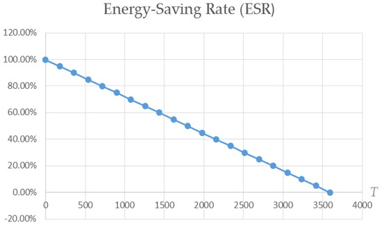
Figure 11.
The relationship between the ESR and T.
4.3. Case Study for ESR Calculation
We used a livestock farm as an example to do energy-saving analysis. We assumed that there were 80 of the proposed extenders on the farm and 80 industrial fans. The proposed extender could transmit wirelessly via a Wi-Fi 2.4G wireless communication module. We could uniformly set each of the farm’s temperature settings for the sockets without wasting human resources by selecting them individually.
The farms bred pigs. In the hot summer, the pig farms face the challenge of high temperatures. Hence, large industrial fans must be used to cool down. The fan model was FS-50, the voltage was 220 V and the rated power was 280 W. For the 1400 RPM industrial fans, if the proposed extender was not used, each fan’s annual power consumption would be as high as 8760 × 0.28 = 2452.8 kw h.
In this application field, through actual measurement and adjustment of the Max (high temperature) and Min (low temperature) values of the proposed extender, we found that when the Max value was 22 °C and the Min value was 20 °C (i.e., the proposed extender was in cooling mode), it was more suitable for pigs weighing 5–40 kg. After actual measurement by the power meter, it was found that the average cumulative start-up seconds T of an industrial fan in an hour was about 900 s. We illustrated its energy-saving effects through the reduced electricity consumption over the same period of one year. Hence, we can directly refer to Table 3 to calculate the related values (now using the Epy, Dpy, Mpy and Cpy values of T = 900 s) as follows.:
- The power consumption of 80 industrial fans using the proposed extender (Epy value of T = 900 is 619.332):
- 619.332 × 80 = 49,546.56 kw⋅h;
- The power consumption of 80 general industrial fans (without using the proposed extender, when can only be fully activated within 24 h):
- 8760 × 0.28 × 80 = 196,224 kw⋅h;
- The reduced power consumption in a year (Dpy value of T = 900 s is 1833.468):
- 1833.468 × 80 = 146,677.44 kw⋅h;
- The cost reduction in one year (Mpy value of T = 900 s is 733.872):
- 7333.872 × 80 = 586,709.76 NT$ (yuan);
- The carbon emissions reduced in one year (Cpy value of T = 900 s is 1142.251):
- 1142.251 × 80 = 91,380.08 kgCO2e.
Therefore, we only needed to add 80 industrial electric fans to the farm and 80 of the proposed extenders to get the expected results, as can be seen in Table 4. We assumed that the fan operated 24 h a day and that the cost was calculated at four yuan per unit (degree). The power consumption of the proposed extender was 0.7 W. The power consumption of the industrial electric fan was 280 W (T = 900 s).

Table 4.
Reduced electricity consumption, cost and carbon emissions of a farm during the same year.
5. User Satisfaction Analysis
We divided satisfaction into three aspects for discussion: whole, home and farm. In this article, there were 249 people in the questionnaire survey, of which 47% were male and 53% were female. The analysis results are shown in Table 5. The average ranking of overall satisfaction found that the top three satisfaction ratings for the IoT-based temperature control power extender settings were “2. I think this IoT-based temperature control power extender can keep the space at a certain temperature without wasting electricity (m = 4.85).” The highest score was “3. I think the function of the IoT-based temperature control power extender’s cooling mode is useful (m = 4.76),” followed by “I think this IoT-based temperature control power extender has an excellent energy-saving effect (m = 4.70).”

Table 5.
Satisfaction analysis form.
In terms of home satisfaction, “When this IoT-based temperature control power extender is used in the home, I think it is very suitable for use when the air conditioner stops and the room temperature rises. The cooling mode is used to start the fan to cool down automatically (m = 4.40),” which was the most-satisfied response by consumers.
Finally, according to the above results, it was found that the satisfaction degree of the proposed IoT-based temperature control power extender used in different areas was farm > home. Moreover, it was found that consumers favored the cooling mode more than the heating mode. From the satisfaction analysis in Table 5, it can be seen that the operating interface scores were all biased to be low. Among them, “I think the temperature setting unit of this IoT-based temperature control power extender is appropriate (currently, the smallest temperature unit that can be set is 1 °C)” was the most important point for review. It may be that consumers wanted the temperature setting unit to be smaller, such as 0.50 °C. In summary, the proposed IoT-based temperature control power extender could keep the space at a certain temperature without wasting electricity so that consumers could be satisfied.
6. Conclusions
The expandable master–slave IoT temperature control extender proposed in this article has been equipped with two working modes: cooling and heating. The power supply can be turned on or off accurately and in a timely manner through the temperature-sensing component, thereby avoiding unnecessary power consumption. It can also be controlled through Wi-Fi 2.4G wireless transmission, uploading real-time temperature information, the switch status, the master–slave mode and other collected data to the cloud server. The terminal device performs parameter settings.
When we used the proposed power extender in large-scale breeding farms, it was found that there were different temperature requirements for pigs of various sizes in the breeding farm. Even the Max and Min values that needed to be set at night and during the day were different. In practice, each area must be adjusted frequently. Fortunately, the proposed power extender can first select the master extender parameters and then immediately transmit the commands to other slave extenders through Wi-Fi 2.4G wireless transmission. Therefore, no human resources are wasted to go to the site and set each power extender.
Recently, many smart machines and pieces of equipment have been dedicated to reducing power consumption. Still, as long as machines and equipment are equipped with smart technology, their prices are usually high, and the existing old machines and equipment do not have smart power-saving functions, so they need to be set manually. This is why IoT-based power extenders have been developed in recent years. Old appliances and equipment can have smart functions through this temperature control extension cord or be remotely controlled through a mobile device. As long as the old devices and equipment are connected to the proposed power extender, they can instantly become intelligent machines and equipment. In future works, we will consider and design cybersecurity with the proposed power extender to avoid network attacks such as false data injection attacks [44], replay attacks [45] and denial of service attacks [46].
Author Contributions
Conceptualization, H.-M.C. and C.-T.L.; methodology, C.-T.L. and L.-B.C.; software, L.-B.C.; validation, C.-T.L., L.-B.C. and Y.-Y.L.; formal analysis, H.-M.C.; investigation, C.-T.L. and L.-B.C.; resources, Y.-Y.L.; data curation, C.-T.L.; writing—original draft preparation, H.-M.C. and C.-T.L.; writing—review and editing, H.-M.C., C.-T.L. and L.-B.C.; visualization, C.-T.L. and L.-B.C.; supervision, L.-B.C.; project administration, C.-T.L. and Y.-Y.L.; funding acquisition, L.-B.C. All authors have read and agreed to the published version of the manuscript.
Funding
This work also was supported in part by the Ministry of Science and Technology (MoST), Taiwan, under Grant MOST 109-2222-E-346-001.
Conflicts of Interest
The authors declare no conflict of interest.
References
- Lee, C.-T.; Ho, P.-T. Energy-saving research on new type of led sensor lamp with low-light mode. Electronics 2020, 9, 1649. [Google Scholar] [CrossRef]
- Lee, C.-T.; Ho, P.-T.; Lee, Y.-Y.; Chen, L.-B. A research on the 4th generation intelligent energy-saving solar water heating tank. Electronics 2020, 9, 1941. [Google Scholar] [CrossRef]
- Karanchery, S.; Rakesh, N. Smart power socket using Internet of Things. In Proceedings of the 2020 International Conference on Inventive Computation Technologies (ICICT), Coimbatore, India, 26–28 February 2020; pp. 1060–1064. [Google Scholar]
- Musleh, A.S.; Debouza, M.; Farook, M. Design and implementation of smart plug: An Internet of Things (IoT) approach. In Proceedings of the 2017 International Conference on Electrical and Computing Technologies and Applications (ICECTA), Ras Al Khaimah, United Arab Emirates, 21–23 November 2017; pp. 1–4. [Google Scholar]
- Thongkhao, Y.; Pora, W. A low-cost Wi-Fi smart plug with on-off and energy metering functions. In Proceedings of the 13th International Conference on Electrical Engineering/Electronics, Computer, Telecommunications Information Technology (ECTI-CON), Chiang Mai, Thailand, 28 June–1 July 2016; p. 15. [Google Scholar]
- Patil, K.; Metan, J.; Kumaran, T.S.; Mathapatil, M. IoT based power management and controlled socket. In Proceedings of the 2017 International Conference on Electrical, Electronics, Communication, Computer, and Optimization Techniques (ICEECCOT), Mysuru, India, 15–16 December 2017; pp. 243–247. [Google Scholar]
- Horvat, I.; Lukac, N.; Pavlovic, R.; Starcevic, D. Smart plug solution based on Bluetooth low energy. In Proceedings of the IEEE 5th International Conference Consumer Electronics-Berlin (ICCE-Berlin), Berlin, Germany, 6–9 September 2015; pp. 435–437. [Google Scholar]
- Lin, Y.-B.; Huang, C.-M.; Chen, L.-K.; Sung, G.-N.; Yang, C.-C. MorSocket: An Expandable IoT-Based Smart Socket System. IEEE Access 2018, 6, 53123–53132. [Google Scholar] [CrossRef]
- Ramavarapu, V.P.; Sowers, R.; Sreenivas, R.S. A smart power outlet for electric devices that can benefit from Real-Time Pricing. In Proceedings of the 2017 International Conference on Control, Electronics, Renewable Energy and Communications (ICCREC), Yogyakarta, Indonesia, 26–28 September 2017; pp. 11–17. [Google Scholar]
- Zhai, S.; Wang, Z.; Yan, X.; He, G. Appliance exibility analysis considering user’s behavior in home energy management system using smart plugs. IEEE Trans. Ind. Electron. 2019, 66, 1391–1401. [Google Scholar] [CrossRef]
- Nurelmadina, N.; Hasan, M.K.; Memon, I.; Saeed, R.A.; Zainol Ariffin, K.A.; Ali, E.S.; Mokhtar, R.A.; Islam, S.; Hossain, E.; Hassan, M.A. A Systematic Review on Cognitive Radio in Low Power Wide Area Network for Industrial IoT Applications. Sustainability 2021, 13, 338. [Google Scholar] [CrossRef]
- Park, M.; Paek, J. On-Demand Scheduling of Command and Responses for Low-Power Multihop Wireless Networks. Sensors 2021, 21, 738. [Google Scholar] [CrossRef]
- DeLucia, D.; Obraczka, K. Multicast feedback suppression using representatives. In Proceedings of the INFOCOM’97, Kobe, Japan, 7–11 April 1997; pp. 463–470. [Google Scholar]
- Ferrari, F.; Zimmerling, M.; Thiele, L.; Saukh, O. Efficient network flooding and time synchronization with glossy. In Proceedings of the 10th ACM/IEEE International Conference on Information Processing in Sensor Networks, Chicago, IL, USA, 12–14 April 2011. [Google Scholar]
- Bedewy, A.M.; Sun, Y.; Shroff, N.B. Age-optimal information updates in multihop networks. In Proceedings of the 2017 IEEE International Symposium on Information Theory (ISIT), Aachen, Germany, 25–30 June 2017; pp. 576–580. [Google Scholar]
- Lu, J.; Whitehouse, K. Flash Flooding: Exploiting the Capture Effect for Rapid Flooding in Wireless Sensor Networks. In Proceedings of the IEEE INFOCOM 2009, Rio de Janeiro, Brazil, 19–25 April 2009. [Google Scholar]
- Ye, F.; Luo, H.; Cheng, J.; Lu, S.; Zhang, L. Hexagonal Two Tier Data Dissemination model for large scale wireless sensor networks. In Proceedings of the 2012 Japan-Egypt Conference on Electronics, Communications and Computers, Alexandria, Egypt, 6–9 March 2012. [Google Scholar]
- Shu, T.; Liu, W.; Wang, T.; Deng, Q.; Zhao, M.; Xiong, N.N.; Li, X.; Liu, A. Broadcast Based Code Dissemination Scheme for Duty Cycle BasedWireless Sensor Networks. IEEE Access 2019, 7, 105258–105286. [Google Scholar] [CrossRef]
- Jeong, G.; Park, M.; Paek, J. A2-Trickle: Adaptive & Aligned Trickle for Rapid and Reliable Dissemination in Low-Power Wireless Networks. IEEE Access 2020, 8, 214374–214382. [Google Scholar]
- Gnawali, O.; Fonseca, R.; Jamieson, K.; Moss, D.; Levis, P. Collection Tree Protocol. In Proceedings of the 7th ACM Conference on Embedded Networked Sensor Systems, Berkeley, CA, USA, 4–6 November 2009; pp. 1–14. [Google Scholar]
- Winter, T.; Thubert, P.; Brandt, A.; Hui, J.; Kelsey, R.; Levis, P.; Pister, K.; Struik, R.; Vasseur, J.; Alexander, R. RPL: IPv6 Routing Protocol for Low-Power and Lossy Networks. Available online: https://tools.ietf.org/id/draft-ietf-roll-rpl-13.html (accessed on 21 January 2021).
- Kim, H.S.; Paek, J.; Bahk, S. QU-RPL: Queue Utilization based RPL for Load Balancing in Large Scale Industrial Applications. In Proceedings of the 2015 12th Annual IEEE International Conference on Sensing, Communication, and Networking (SECON), Seattle, WA, USA, 22–25 June 2015. [Google Scholar]
- Jeong, S.; Paek, J.; Kim, H.S.; Bahk, S. TESLA: Traffic-aware Elastic Slotframe Adjustment in TSCH Networks. IEEE Access 2019, 7, 130468–130483. [Google Scholar] [CrossRef]
- Kim, H.S.; Paek, J.; Culler, D.E.; Bahk, S. PC-RPL: Joint Control of Routing Topology and Transmission Power in Real Low-Power Lossy Network. ACM Trans. Sens. Netw. 2020, 16, 1–32. [Google Scholar] [CrossRef]
- Jeong, S.; Park, E.; Woo, D.; Kim, H.S.; Paek, J.; Bahk, S. MAPLE: Mobility Support using Asymmetric Transmit Power in Low-power and Lossy Networks. J. Commun. Netw. 2018, 20, 414–424. [Google Scholar] [CrossRef]
- Hao, S.; Zhang, H. MAC Performance Analysis for Reliable Power-Line Communication Networks with ARQ Scheme. Sensors 2021, 21, 196. [Google Scholar] [CrossRef] [PubMed]
- Saban, M.; Medus, L.D.; Casans, S.; Aghzout, O.; Rosado, A. Sensor Node Network for Remote Moisture Measurement in Timber Based on Bluetooth Low Energy and Web-Based Monitoring System. Sensors 2021, 21, 491. [Google Scholar] [CrossRef] [PubMed]
- Režek Jambrak, A.; Nutrizio, M.; Djekić, I.; Pleslić, S.; Chemat, F. Internet of Nonthermal Food Processing Technologies (IoNTP): Food Industry 4.0 and Sustainability. Appl. Sci. 2021, 11, 686. [Google Scholar] [CrossRef]
- Baire, M.; Melis, A.; Lodi, M.B.; Dachena, C.; Fanti, A.; Farris, S.; Pisanu, T.; Mazzarella, G. WSN Hardware for Automotive Applications: Preliminary Results for the Case of Public Transportation. Electronics 2019, 8, 1483. [Google Scholar] [CrossRef]
- Wu, D.; Ren, J.; Davies, H.; Shang, J.; Haas, O. Intelligent Hydrogen Fuel Cell Range Extender for Battery Electric Vehicles. World Electr. Veh. J. 2019, 10, 29. [Google Scholar] [CrossRef]
- Lee, C.-Y.; Chen, C.-H.; Lee, T.-J.; Cheong, J.-S.; Liu, Y.-C.; Chen, Y.-C. Flexible Five-in-One Microsensor for Real-Time Wireless Microscopic Diagnosis inside Electric Motorcycle Fuel Cell Stack Range Extender. Micromachines 2021, 12, 103. [Google Scholar] [CrossRef]
- Kalia, A.V.; Fabien, B.C. On Implementing Optimal Energy Management for EREV Using Distance Constrained Adaptive Real-Time Dynamic Programming. Electronics 2020, 9, 228. [Google Scholar] [CrossRef]
- Guan, J.-C.; Chen, B.-C.; Wu, Y.-Y. Design of an Adaptive Power Management Strategy for Range Extended Electric Vehicles. Energies 2019, 12, 1610. [Google Scholar] [CrossRef]
- Xi, L.; Zhang, X.; Sun, C.; Wang, Z.; Hou, X.; Zhang, J. Intelligent Energy Management Control for Extended Range Electric Vehicles Based on Dynamic Programming and Neural Network. Energies 2017, 10, 1871. [Google Scholar] [CrossRef]
- Shadoul, M.; Yousef, H.; Abri, R.A.; Al-Hinai, A. Adaptive Fuzzy Approximation Control of PV Grid-Connected Inverters. Energies 2021, 14, 942. [Google Scholar] [CrossRef]
- Wang, X.; Lv, H.; Sun, Q.; Mi, Y.; Gao, P. A Proportional Resonant Control Strategy for Efficiency Improvement in Extended Range Electric Vehicles. Energies 2017, 10, 204. [Google Scholar] [CrossRef]
- Ali, M.N.; Mahmoud, K.; Lehtonen, M.; Darwish, M.M.F. Promising MPPT Methods Combining Metaheuristic, Fuzzy-Logic and ANN Techniques for Grid-Connected Photovoltaic. Sensors 2021, 21, 1244. [Google Scholar] [CrossRef]
- Richter, F.; Niemann, P.; Schuck, M.; Grabe, J.; Schmitz, G. Comparison of Conventional and Variable Borehole Heat Exchangers for Use in a Desiccant Assisted Air Conditioning System. Energies 2021, 14, 926. [Google Scholar] [CrossRef]
- Zhou, Y.; Qi, B.; Zheng, M.; Cong, B. A Novel DC Bias Suppression Strategy for Single-Phase Full-Bridge DC-DC Arc Welding Converter. Electronics 2021, 10, 428. [Google Scholar] [CrossRef]
- Kang, L.; Zhang, J.; Zhou, H.; Zhao, Z.; Duan, X. Model Predictive Current Control with Fixed Switching Frequency and Dead-Time Compensation for Single-Phase PWM Rectifier. Electronics 2021, 10, 426. [Google Scholar] [CrossRef]
- Corti, F.; Reatti, A.; Wu, Y.-H.; Czarkowski, D.; Musumeci, S. Zero Voltage Switching Condition in Class-E Inverter for Capacitive Wireless Power Transfer Applications. Energies 2021, 14, 911. [Google Scholar] [CrossRef]
- Benoit-Cattin, T.; Velasco-Montero, D.; Fernández-Berni, J. Impact of Thermal Throttling on Long-Term Visual Inference in a CPU-Based Edge Device. Electronics 2020, 9, 2106. [Google Scholar] [CrossRef]
- Al-Fuqaha, A.; Guizani, M.; Mohammadi, M.; Aledhari, M.; Ayyash, M. Internet of Things: A survey on enabling technologies protocols and applications. IEEE Commun. Surv. Tutor. 2015, 17, 2347–2376. [Google Scholar] [CrossRef]
- Zhu, S.; Setia, S.; Jajodia, S.; Ning, P. Interleaved hop-by-hop authentication against false data injection attacks in sensor networks. ACM Trans. Sens. Netw. 2007, 3, 14. [Google Scholar] [CrossRef]
- Hosseinzadeh, M.; Sinopoli, B.; Garone, E. Feasibility and Detection of Replay Attack in Networked Constrained Cyber-Physical Systems. In Proceedings of the 2019 57th Annual Allerton Conference on Communication, Control, and Computing (Allerton), Monticello, IL, USA, 24–27 September 2019; pp. 712–717. [Google Scholar]
- Pelechrinis, K.; Iliofotou, M.; Krishnamurthy, S.V. Denial of Service Attacks in Wireless Networks: The Case of Jammers. IEEE Commun. Surv. Tutor. 2011, 13, 245–257. [Google Scholar] [CrossRef]
Publisher’s Note: MDPI stays neutral with regard to jurisdictional claims in published maps and institutional affiliations. |
© 2021 by the authors. Licensee MDPI, Basel, Switzerland. This article is an open access article distributed under the terms and conditions of the Creative Commons Attribution (CC BY) license (http://creativecommons.org/licenses/by/4.0/).