1. Introduction
The Polynesian voyaging canoe was the historical vessel of exploration, discovery, and communication for Pacific Islanders. Inspired by this, the CyberCANOE is the Cyber-enabled “vessel” of Collaboration, Analysis, Navigation, and Observation for University of Hawaiʻi (UH) researchers and students in the era of data-intensive science. The CyberCANOE project seeks to construct display rich environments to support collaborative science, engineering, and education in the Hawaiian Islands. Since 2014, there have been 14 CyberCANOEs deployed in Hawaiʻi and are used in numerous disciplines in Science, Engineering, Medicine, and the Arts. CyberCANOEs come in a variety of configurations (or “classes”) which vary in total display resolution and capabilities, such as, stereoscopic 3D and six degrees of freedom (DOF) tracking.
Table 1 shows the varying configurations of CyberCANOEs in Hawaiʻi.
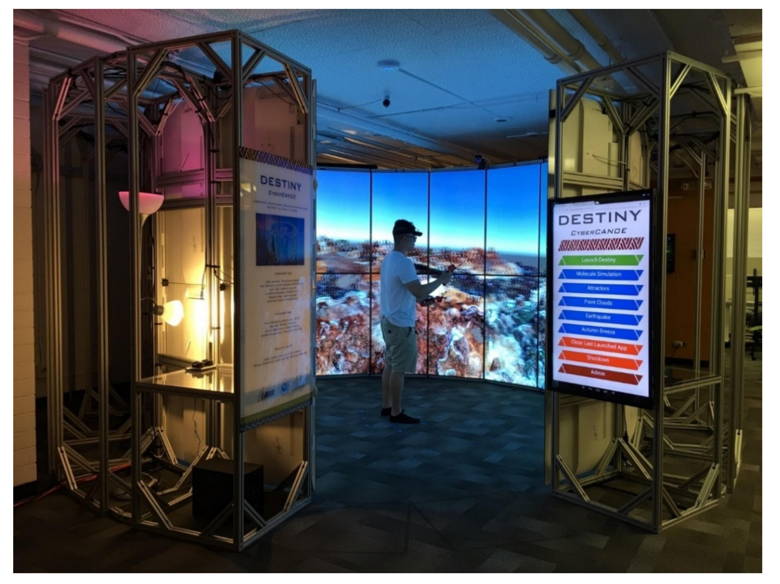
This paper describes the Destiny-class CyberCANOE,
Figure 1 which is a Hybrid Reality environment consisting of a 320-degree tiling of displays, shown in
Figure 2, similar to CAVE2 [
1]. However, Destiny differs from CAVE2 and other similar systems [
2], such as the TourCAVE and WAVE [
3] in a number of important ways: Destiny has higher total resolution, uses off-the-shelf OLED 4K displays, and is constructed at 1/3 the cost of CAVE2 but with 3.6 × the resolution. The technology improvements of off-the-shelf consumer grade displays enabled Destiny to be constructed at a fraction of the cost since it did not depend on commercial grade equipment. Destiny is intended as a system that can provide close to 20/20 acuity that overcomes the resolution limitations of current low-cost head mounted displays, such as the HTC Vive and Oculus Rift. Most importantly, Destiny uses a software-based approach to mitigate off-axis stereo crosstalk, which significantly reduces overall cost of the system when compared to CAVE2′s physically based crosstalk mitigation solution, which uses custom LCD panels.
The primary contribution of this paper is to chronicle the non-trivial engineering research and attention-to-detail that is needed to develop a production quality Hybrid Reality environment. We believe this degree of detail will be useful to virtual reality (VR) practitioners who wish to develop similar environments in the future. This paper will therefore endeavor to: (1) provide a detailed account of how a Hybrid Reality system is designed and constructed from the ground up to help VR researchers and developers understand the engineering complexity of developing such systems, (2) describe the issues involved in the use of newly emerging organic light-emitting diode displays (OLED) rather than liquid crystal displays (LCD), (3) explore the use of an augmented reality (AR) device as part of the design and construction process, (4) the use of a software-based approach to mitigate off-axis stereoscopic crosstalk.
2. Physical Design and Construction
The goal was to build a system capable of providing nearly 20/20 acuity, so the viewer would not be able to see the individual pixels as on the HTC Vive [
4] or Oculus Rift [
5]. Consequently, emphasis on image quality (brightness, contrast, acuity) over other existing VR systems was paramount.
Current Hybrid Reality Systems such as CAVE2 are constructed with tiled LCDs. All pixels within an LCD are illuminated by a backlight, while pixels within an OLED display are self-illuminated. This allows the off state of an OLED display pixel to produce perfect image blacks resulting in an infinite contrast ratio and an infinite dynamic range [
6], which provides a superior image brightness and contrast compared to LCDs.
Destiny is intended for use in scientific, engineering, medical, and art visualizations that can benefit from high resolution 2D and 3D environments. The system should provide an image that can fully envelop a user’s field of view. Lastly, and perhaps most importantly, the system must be comfortable to use for long periods of time which is possible through minimal encumbrance.
3. Implementation of the Physical Structure
Destiny’s physical implementation was influenced by available technologies, off-axis field of view (FOV) limitations, and targeted acuity. OLED active stereo displays are not commercially available resulting in the decision to use OLED passive stereo displays. While 65″ displays were available, 55″ displays provided greater pixel density which allowing us to achieve near 20/20 visual acuity. LG displays were used over others due to their ease of tiling and their minimal bezel. Consequently, Destiny was built using passive stereo 55″ LG OLED 4K televisions (model number 55EF9500).
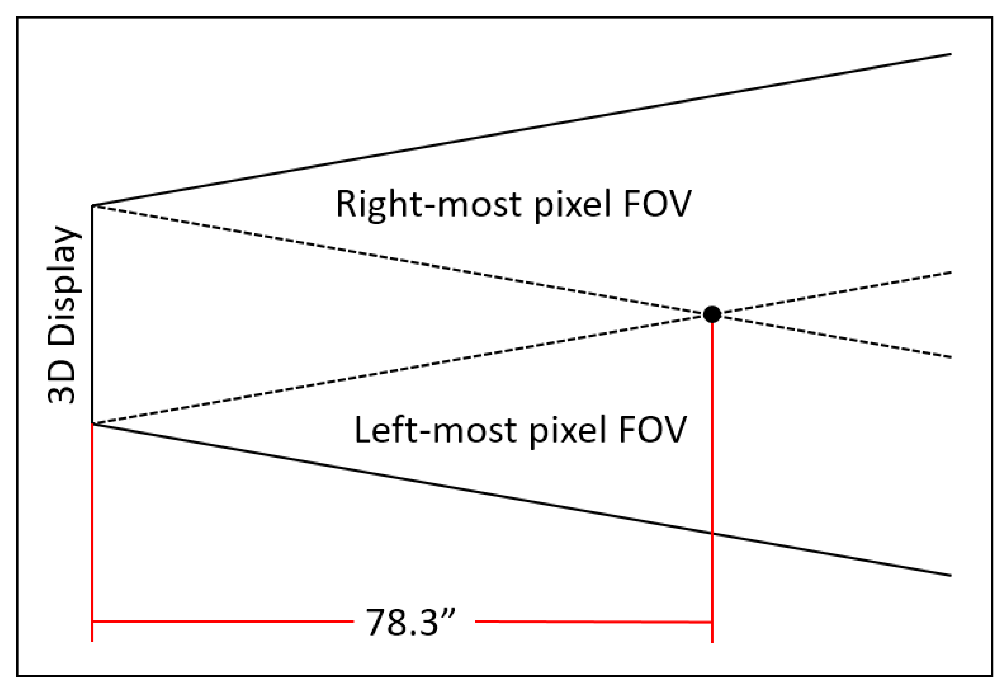
The OLED displays (in portrait orientation) have a height and width of 48.25 × 27.625 inches. Passive stereo-enabled LCDs have a vertical 3D FOV of 20 degrees when placed in the landscape orientation [
1,
2]. The OLED displays in Destiny were found to have approximately the same FOV. The minimum viewing distance of the entire display can be calculated at the intersection of the leftmost and rightmost pixel FOV lines, Minimum 3D Viewing Distance = (Display Width)/(2 (tan(10°)))
Any given display in Destiny has a minimum viewing distance of 78.335-inches,
Figure 3. Stereoscopic acuity can be calculated using the minimum viewing distance and the display’s technical specifications,
Table 2.
The number of necessary display columns can be calculated using this equation, number of columns = (π/tan−1) (display width/(2 (minimum viewing distance))), yielding 18 sides. Two columns are absent to provide a gap for entry and exit, with a width of 55.2-inches, making Destiny wheelchair accessible.
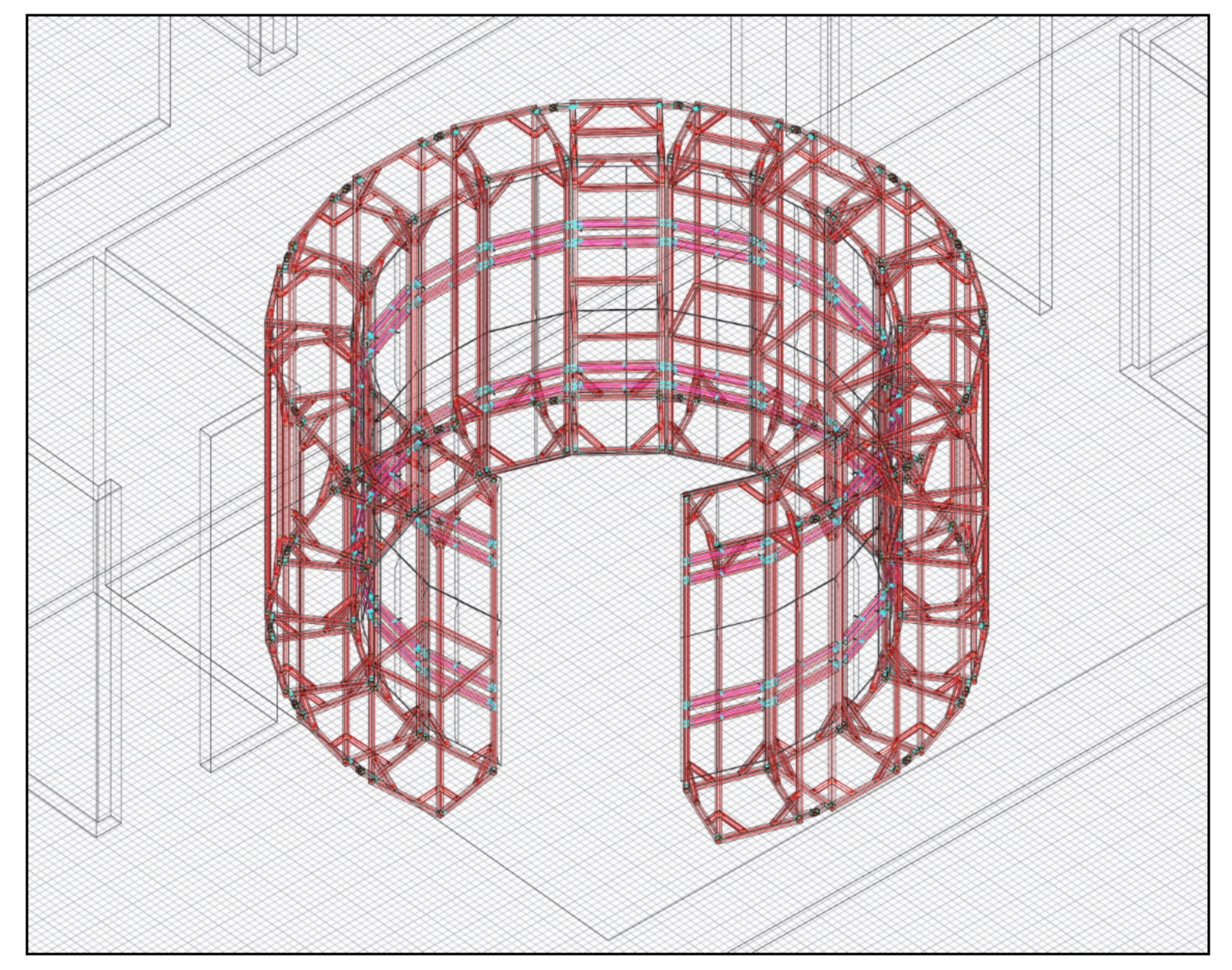
Destiny was constructed with extruded aluminum from 80/20 Inc. and designed in AutoCAD using 80/20′s plugin (
Figure 4). Each column’s base matches the width dimension of the displays (27.625-inches). The vertical structure was designed as a rectangular prism which provided stability and easy linkage to adjacent columns. 45-degree angle extrusions secure the vertical pillars and are used to support the video and power cables. In addition to providing stability, the extra column space is used as a shelving for the computer cluster. The 80/20 Inc. build design required no custom parts, therefore reducing the cost and assembly time required for the system.
4. Use of the HoloLens
The PARIS paper inspired us to utilize recently released VR or AR technologies to aid us in the development of Destiny [
7]. The HoloLens [
8] was used in the initial design and construction of Destiny. After the 80/20 Inc. [
9] plan was completed in AutoCAD [
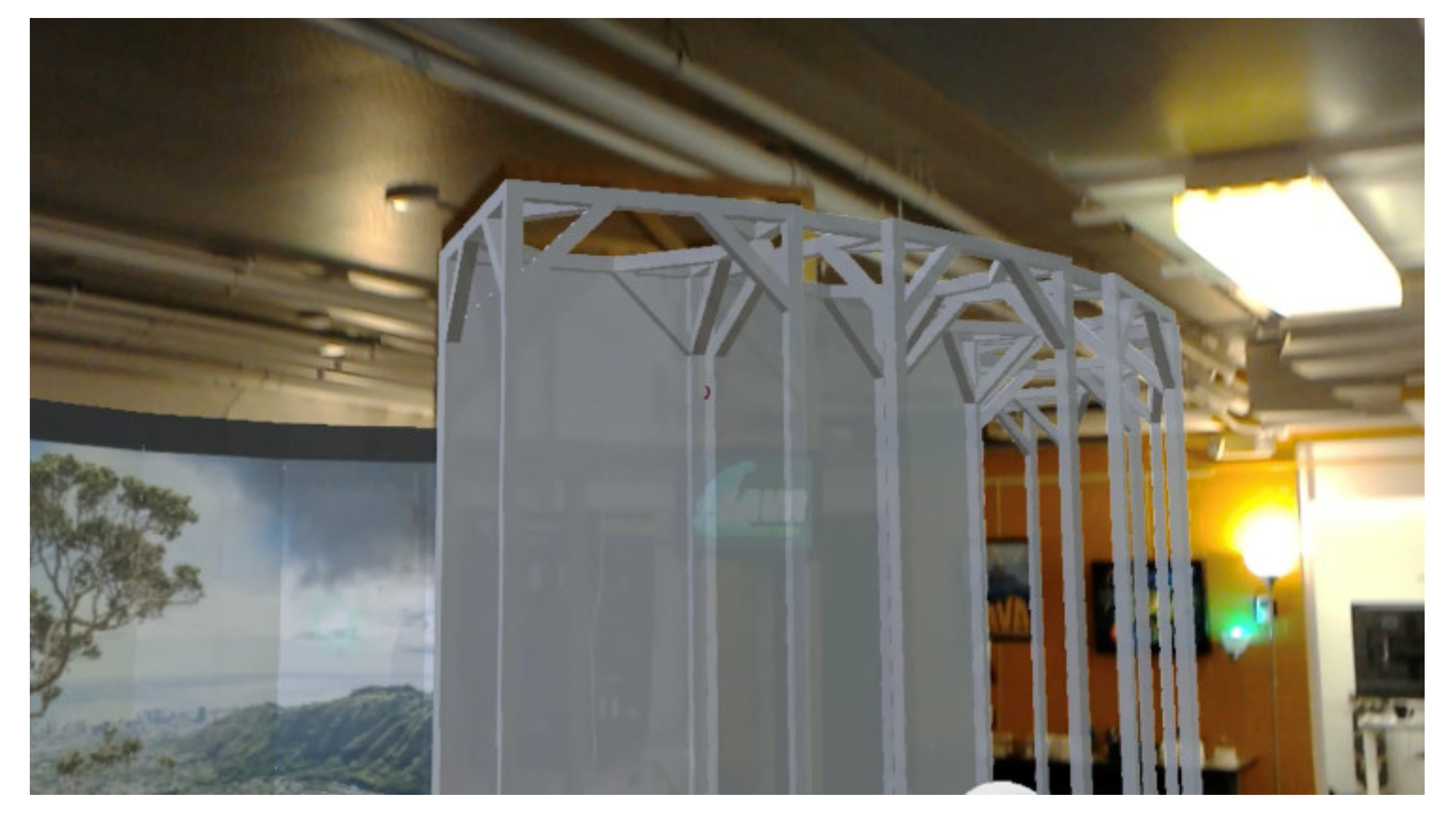
10], the model was imported into Unity for use in the HoloLens. Utilizing the HoloLens, it was possible to superimpose a one-to-one scale model of Destiny within the physical space designated for its installation,
Figure 5. This allowed for the determination of proper placement, orientation, and whether the design could clear physical constraints such as ventilation ducts and electrical conduits that existed in the room.
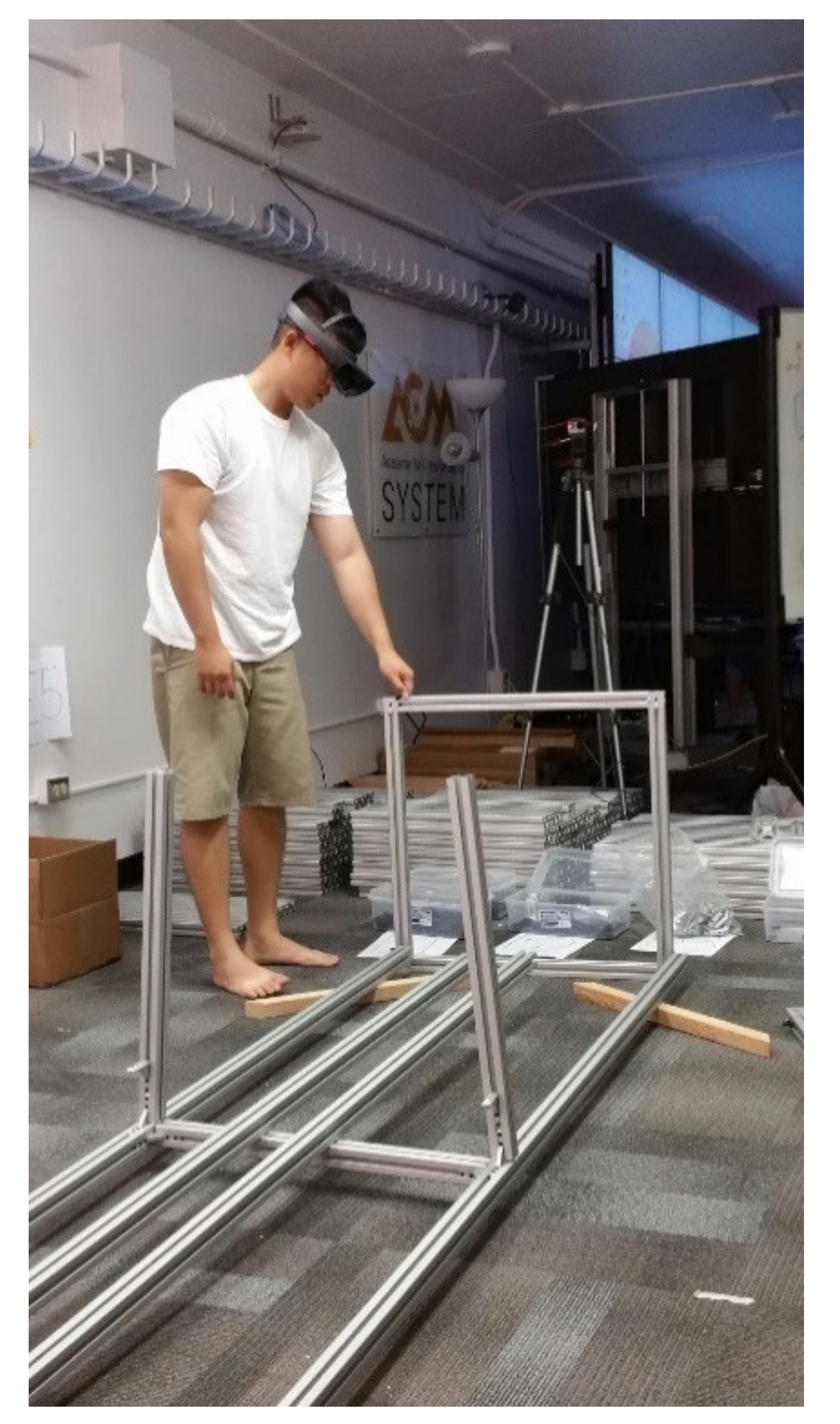
Destiny was constructed entirely by students unfamiliar with the build process, therefore training was required. We took this opportunity to conduct a brief user-study with six participants to compare two training approaches. In the first approach, three participants used the HoloLens, which presented a one-to-one scale AR representation of the parts and assembly steps that were superimposed on top of the physical parts for the same column construction process,
Figure 6.
The second approach involved three participants given a traditional paper instruction manual consisting of 2.5D orthographic diagrams,
Figure 7.
HoloLens users reported a variety of issues during the assembly process. The small FOV requires head movement, as opposed to eye movement, in order to see a full scene. The HoloLens also had a tendency to enter sleep mode when not interacted with for a brief period of time. This resulted in the need to frequently relaunch and recalibrate the Destiny construction application. Users trained with the HoloLens took twice as long to complete their construction than those using the paper manual. However, by comparison to those given the paper manual, the HoloLens group reported greater confidence that they would not require any reference material for further construction tasks. More rigorous studies are needed to determine whether this greater confidence is a result of users having spent more time with the HoloLens or whether the augmented reality presentation was the primary contributor. We did not repeat the experiment as construction time constraints did not allow us to disassemble and reassemble the structure. However, despite the challenges in using the HoloLens for the assembly process, it proved very useful during the design phase to evaluate the fit of Destiny within the constraints of the physical space.
5. 3D Printed Parts for Display Support and 6-Degree of Freedom Tracking
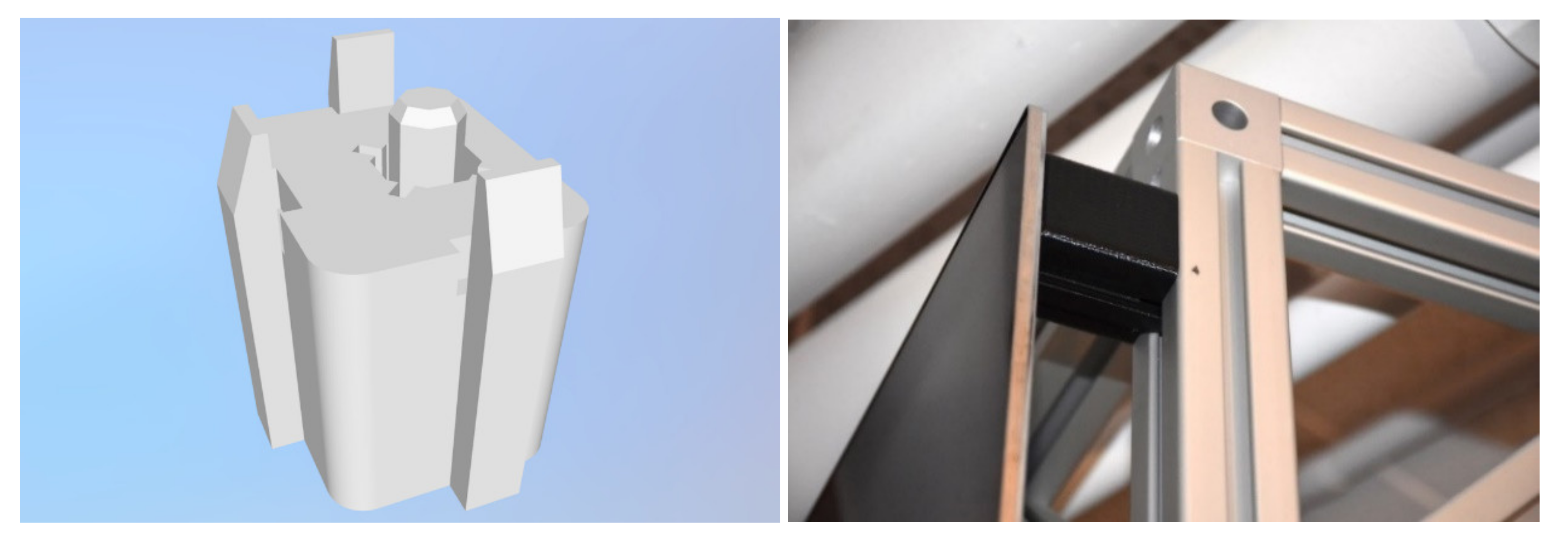
As the OLED TVs were so thin, additional support was needed to prevent bowing. Hence 3D printed spacers were designed and created (using AutoDesk Inventor and Makergear M2 3D Printers). The spacers are mounted between the corners of the displays and columns ensuring that each display-maintained rigidity.
Figure 8 shows one of the spacers and its respective CAD design.
In order to capture hand and head movement of the user, a series of four OptiTrack Prime 13W [
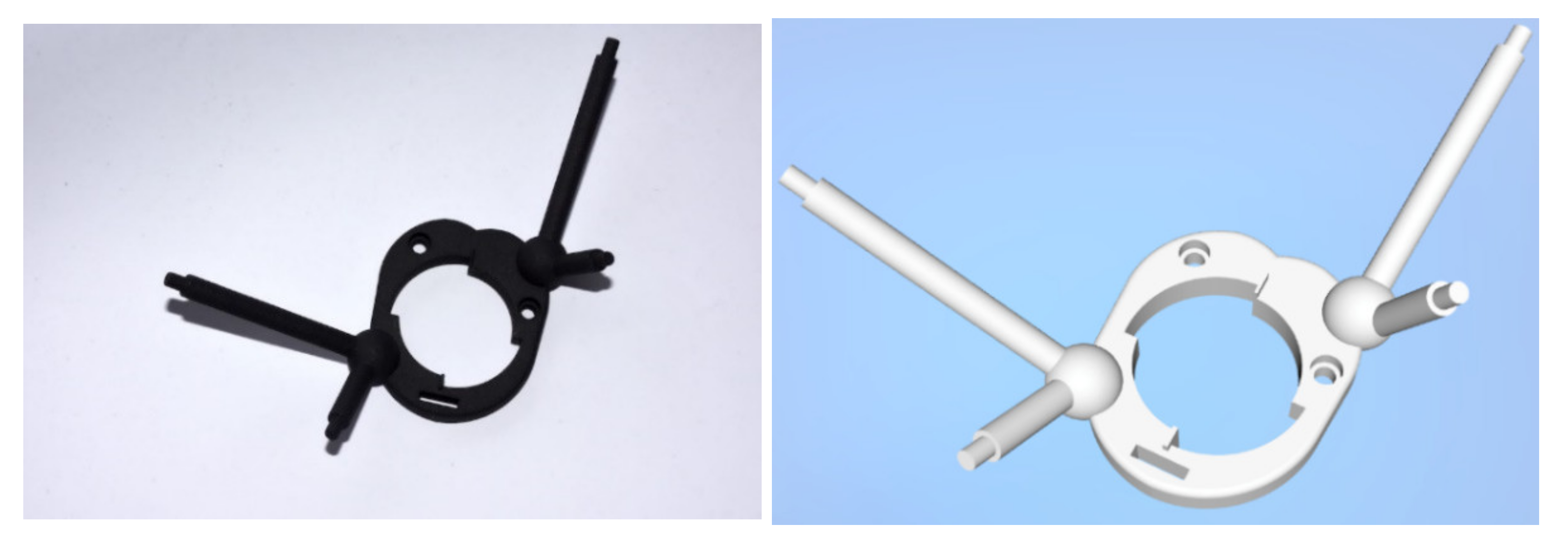
11] cameras were mounted around the Destiny frame above the displays. Unique 3D printed rigid body bases were created,
Figure 9, to hold the retroreflective markers required for motion tracking. The wands are created from half of a dreamGEAR PS3 Move Equalizer shotgun holster, to which a PlayStation Move controller and the custom 3D printed motion capture base was attached. Four motion capture markers were deemed sufficient for tracking each wand, shown in
Figure 10. Another motion capture base of a slightly differing arrangement of tracking markers were designed to support a second wand to permit two-handed interaction. For tracking the user’s head, we utilized OptiTrack’s provided rigid body base attached to a head visor using Velcro. The head visor has four motion capture markers.
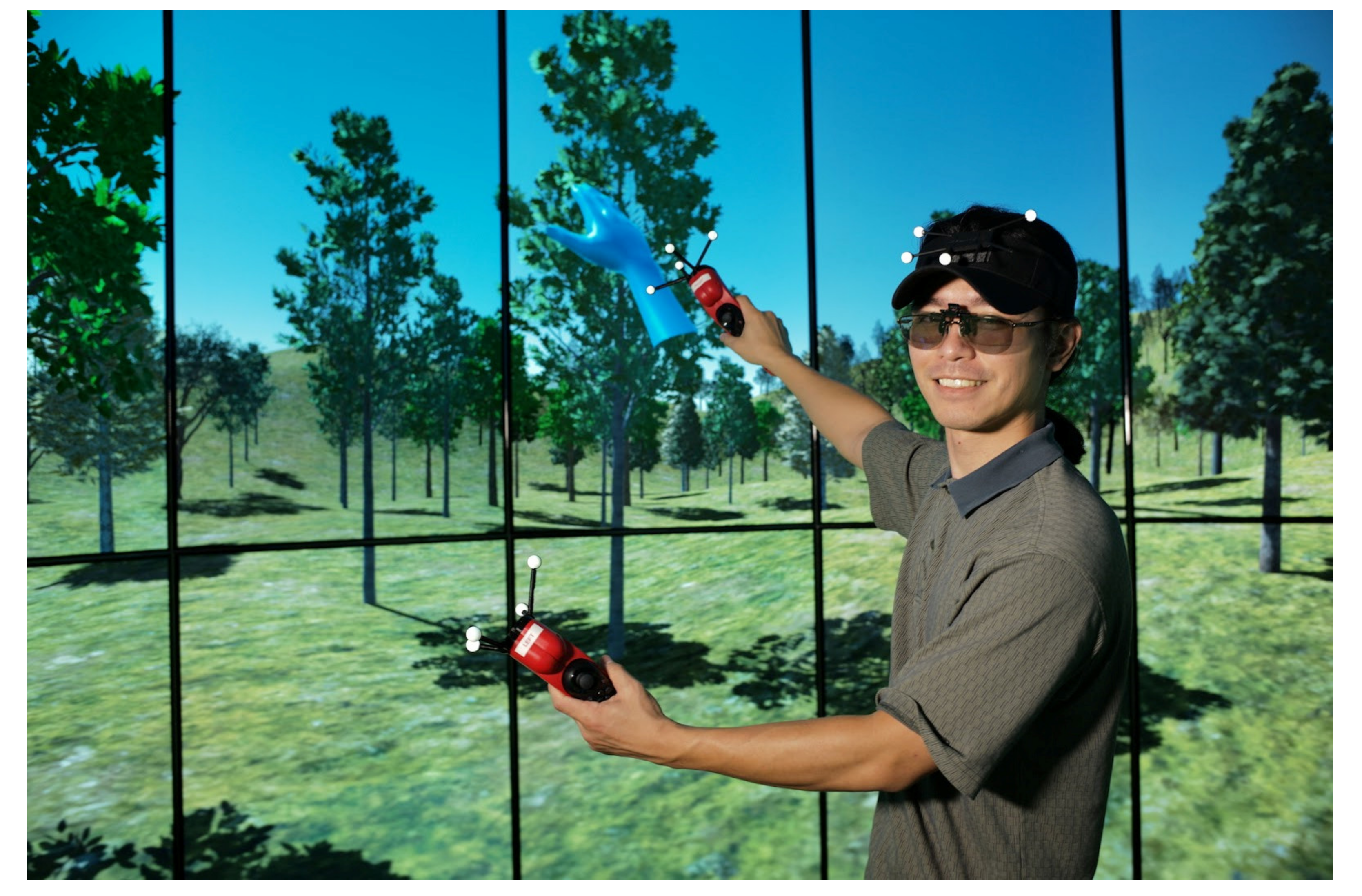
Figure 11 shows a student wearing the tracked devices in Destiny.
6. Computing Hardware Implementation
Destiny’s display capabilities require a large amount of graphic rendering power. The classic approach to driving a high-resolution multi-display system is via a cluster of computers [
12,
13,
14]. The ultimate “dream” is to be able to drive the entire system with a single computer eliminating state synchronization issues between instances running on individual cluster nodes. As PCI Express bandwidth and graphics power has dramatically improved since the original CAVE in 1992 [
15,
16], and most of the CyberCANOEs deployed in the past four years are driven by a single PC, we decided to conduct an experiment to determine the maximum resolution one could drive in a modern high-end PC, while achieving a reasonable frame rate for a prototypical VR data set that runs at 60 Hz in the CAVE2.
Our PC consisted of an Intel Core i7 5960X 3.0GHz (Intel, Santa Clara, CA, USA), 64GB DDR4 2400MHz RAM, 1TB Samsung 850 Evo SSD (Samsung, Seoul, South Korea), 4 Nvidia GTX 980 (Nvidia, Santa Clara, CA, USA), running under Windows 10 64-bit (Microsoft, Redmond, WA, USA).
Omegalib [
17], a Hybrid Reality visualization framework, was used for the system validation. A point cloud of the island of Oʻahu in Hawai’i, several asteroids, and a 3D model of the International Space Station, served as the test scene as it was typical of the type and complexity of the datasets we worked with. Varied numbers of Omegalib instances at different resolutions were used in order to find the optimal number of computing nodes to efficiently display screen resolution at the desired acuity and refresh rate.
Initial testing with a 16-display configuration at 61,440 × 2160 resolution showed that the system would not boot into Windows in a timely manner and even the Windows explorer would not respond correctly. After some troubleshooting Omegalib was able to start. However, OmegaLib crashed upon initial load of the data sets. We then systematically continued to scale down the number of displays to eventually four at a resolution of 15,360 × 2160 without further success— each time Windows became more responsive but Omegalib continued to fail. We decided that perhaps it was not possible for Omegalib to launch windows of such a high resolution, so we configured Omegalib to render multiple windows/graphics instances with an aggregate resolution that reached the target resolution. By doing so we were able to drive as many as eight displays with four graphics instances/windows as well as eight displays and eight instances, however both operating at no more than 15 frames-per-second. At four displays with one instance per display we managed to double the frame rate to 30 fps.
7. Comparison to Other Hybrid Reality Systems
Table 3 summarizes Destiny’s capabilities using similar comparison metrics from Ponto [
2], while also comparing to other Hybrid Reality systems [
1,
15]. In addition to providing significantly better contrast and color gamut, due to its use of OLED displays, Destiny also has 3.6 × the resolution of CAVE2, the former best-in-class Hybrid Reality system. Furthermore, while CAVE2 cost over
$900 K to build, Destiny only cost
$250 K.
8. Display Matrix Communication
A common problem when using consumer TVs as compared to digital signage displays is that consumer TVs were never intended to be used in a matrix. It is impractical to use the provided infrared TV remote to attempt to power on control individual displays and configure them without interfering with other displays. In order to simultaneously control multiple displays, we explored two methods: 1. WebOS Mobile [
18] TV ON feature and 2. serial port communication.
According to LG’s display specifications, the Mobile TV ON function would allow a Wake-On-LAN packet to power on the display through its network card. However, on actual testing we found that the LG model (55EF9500) (LG, Seoul, South Korea) does not support this feature. Our second method was to use the service port on the displays to access the controls. The difficulty of this method was finding the correct serial communication method needed to communicate with the displays and the custom wiring to the serial port.
The service port method required the use of a USB to RS-232 and a RS-232 to 3.5 mm stereo (TRS) converter cable. Our initial testing with this configuration failed to control the displays. Further research in the LG serial communication manual found that the wiring configuration needed a custom setup. Rewiring the two converter cables resulted in the complete control of the display settings. Later work was done to add additional converter cables to safely direct the connections in the correct configuration.
The communication parameters and the transmission messages between displays and computer are shown in
Table 4:
This was tested and confirmed to work in the command prompt of the connected computer. To make it easier for the end user, a batch (.bat) file was created that sets the communication parameters and transmits the power ON signal to the displays. A separate but similar .bat file was created for display shutdown.
9. Supporting Turnkey Control of Destiny
To streamline the process of application installation, launching, closing, powering on and off the entire system, and adjusting settings for Destiny, a web server-based control system was developed. Application deployment on Destiny is done through a control computer apart from the eight compute nodes. A Node.js [
19] server application was created to support all the required tasks. The choice to use Node.js was to avoid complications from Remote Desktop Protocols, enable easy access through a browser, create interfaces with HTML, and avoid making specific versions for each node. Node.js enables access to the file system, ability to run executables, and establish WebSocket communication from the control computer to the compute nodes. The control computer manages launching of applications, controls power on/off, and controls the displays.
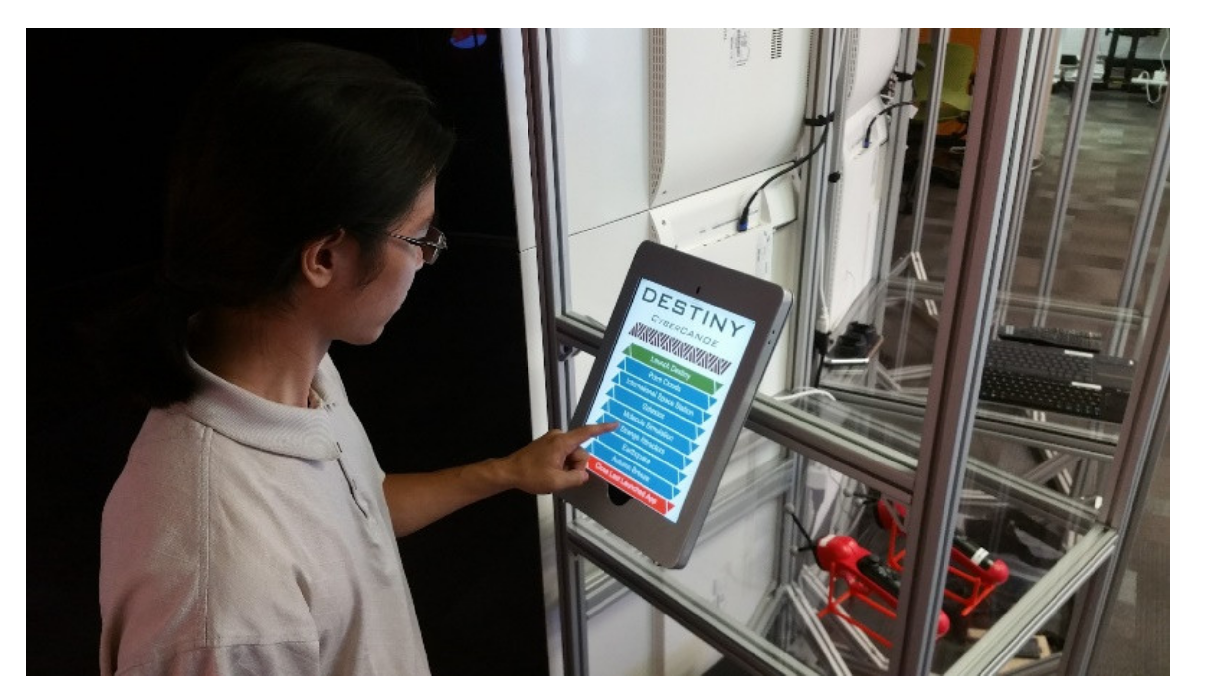
Using Node.js allows any user on the network to control Destiny with a browser; be it on desktop, laptop, or mobile device. A touch screen display powered by an Android mini-PC with a web browser directed at the control page is mounted at the entrance of Destiny. Webpage functionality and layout was designed with consideration to this touch screen. The touch screen is a 55″ 4 K Seiki TV (Seiki Digital, Diamond Bar, CA, USA) with an infrared overlay sensor from PQ Labs. The sensor is PQ Labs’ G5 Multi-Touch Ultimate series [
20]. As of writing, the TV has been replaced with a more responsive Apple iPad Pro 12.9-inch in
Figure 12.
Initial design of the user interface was one main page that read a JSON configuration file that populated the buttons being displayed. Those unfamiliar with HTML or JavaScript were able to update the main page by modifying an entry in the configuration file. Button functionality included powering on Destiny, launching applications, closing the current application, and powering off Destiny. Currently there are three pages in use: main page (
Figure 13), launched application page (
Figure 14), and an admin page (
Figure 15). The other two pages were necessary for cases when someone unfamiliar with the system interacts with the main page and during times of high application turn over. The main page still retains the functionality as described before but also shows node connection status. The Node.js server will start with the operating system and connect to the control computer. In addition, when a node goes down (normally or abnormally), this breaks the connection, and the control computer will immediately know.
When all eight nodes have connected or when an application is closed, the control computer will issue a command to the cluster nodes to launch a full screen Chrome browser that randomly moves our laboratory’s logos over a black background. This prevents burn-in on the OLED displays and give a visual notification when the system is ready. Currently, all applications for Destiny are built in Unity. When an application is launched, the nodes may show the desktop for a few seconds or wait at the Unity logo screen due to resources being loaded for the application. The launched application page was necessary to prevent unnecessary additional launches or cancellation when a user is impatient. After launching an application, the browser would be redirected to the application launched page that has a dynamic loading screen. The page contains a close app button with two stages located towards the top. First click will reveal a second confirm button that needs to be pressed within three seconds. This is to prevent accidental application closure from other users waiting at the entrance.
The admin page performs a variety of other actions in addition to launching applications specified in the configuration file. An entry in the configuration file is necessary to show up on the main page. For quick testing, editing the configuration file is a hindrance and the developers will usually not want incomplete apps shown on the main page. All applications must be fully contained in a folder with the same name as the executable. A designated application folder holds all applications. After a user accesses the admin page, the control computer generates a list of applications by checking the application folder. This list is then used to allow launching of any uploaded application through the admin page.
The control computer has mapped network drives to each of the compute nodes. This enables the admin page to check what applications are available and easy adding and removing of applications by hand. The process to add and remove applications was also automated with a C# program. The interface allows users to select an application folder on the control computer to upload to Destiny or select an application folder on Destiny nodes for removal.
Commands issued through the control computer typically activate a .bat file. The message dispatch system was designed such that the configuration file specifies what messages are available and a path to a .bat file which the message activates. The .bat files also accept parameters for generic usage between the nodes. This allows configuration file edits to easily and quickly alter what buttons are available without needing to alter the core of the system. Apps launched on the different nodes need to know their physical positioning in Destiny to correctly show their viewport. Rather than have node specific changes in the message system or .bat files, instead the message system will have the nodes pass their hostname or IP address as a parameter.
This works well for actions needed once the system is online. However, to start the system the control computer must take a different approach. As mentioned in the previous section, the control computer connects to each of the display’s service port through a direct USB to RS-232 line. This allows the control computer to dispatch display commands regardless of the corresponding node being online.
A power on command dispatched to Destiny takes two main actions. Starting with the first node, the control computer will begin by sending a power on message (one at a time) to each of its displays’ service port over RS-232. After each of a node’s displays have been issued a power on, the control computer will wait briefly before sending the node a Wake-On-LAN packet. This process is repeated for each node. Displays are powered on before the computer to avoid accidental detection of a different display configuration. If a different display configuration is detected, all display settings must be corrected. As part of Window’s startup procedure, each node launches Node.js to check in with the control computer through a WebSocket. The power on process is shown in
Figure 16.
Once a node has checked in, the control computer can dispatch commands as shown in
Figure 17. Each node has a fixed IP address and hostname. Hostnames are suffixed with number 1 to 8 indicating which section of Destiny they correspond to. During check in, the control computer is able to detect node IP address and hostname to determine when Destiny is fully connected.
Code was constantly in flux throughout the development of the of the controller. Alterations required redeployment across all of Destiny’s nodes and restarting the server. This motivated having each node run the same software through generic command handling. Git is used for version control. With each node running the same software, updating can be done through a Git pull from an online repository as shown in
Figure 18. Automated updating is done through two .bat files. Two are necessary because, any process started with Node.js will be terminated when the Node.js server goes down. The first .bat file launches a separate Command Prompt window with the start command to run the second .bat file. Using the start command will launch a separate process that enables it to continue running even if the originating process terminates. The second .bat file will wait while Node.js closes, then perform a Git update, and finally restart the Node.js server.
10. Unity Virtual Reality Development Package
Unity [
21] is used for application development due to its gradual learning curve, cross platform development support, and highly supportive community. Unity provides a cluster rendering solution which allows multiple machines to simulate the same scene in-sync with each other on multiple computers. The master node syncs all worker nodes through a synchronization method called frame locking. Input, time, and random number seed are synced between all nodes.
While Unity provides a cluster rendering solution, the solution is not sufficient for VR application development. Following in the footsteps of our predecessors [
22,
23,
24], we recognized the need to provide an easy-to-use application program interface (API) to support VR application development for use in Destiny. The CyberCANOE API allows developers to focus on creating their applications rather than configuring Unity to work with Destiny. The API provides the following:
Multi-camera configuration
GPU shader stereo interleaving
Head and wand tracking within the Unity scene
User controller input
Each of Destiny’s eight computers output to four displays with a total resolution of 4320 × 8192. Each computer’s four displays span two columns as shown in
Figure 19.
Within Unity we use four different cameras per computer to account for the angle between each column and the bezel between each display. To allow for off-axis projection we follow Kooima’s example [
25]. Each camera has two child cameras that represent the left and right eye. These cameras are separated by 55 mm to account for interpupillary distance. All cameras output to an individual RenderTexture which are passed into a fragment shader. The fragment shader stitches and interlaces all the cameras’ render textures together to form one final RenderTexture. This final RenderTexture is then rendered to the displays.
The API retrieves head and wand tracking information over Virtual Reality Peripheral Network (VRPN) [
26] and translates the designated game objects to their correct real world position and orientation. Developers are able to retrieve each tracked object’s position and rotation through the API.
Destiny uses two Sony PS3 Move controllers for user input. These controllers have no native support on Windows. To circumvent this problem we use an open source driver, ScpToolkit [
27]. This driver enables Sony Dualshock controllers to connect to Windows over a Bluetooth connection and their input to be seen as standard XInput. A VRPN server then hosts these inputs to allow developers to interface with them through our API.
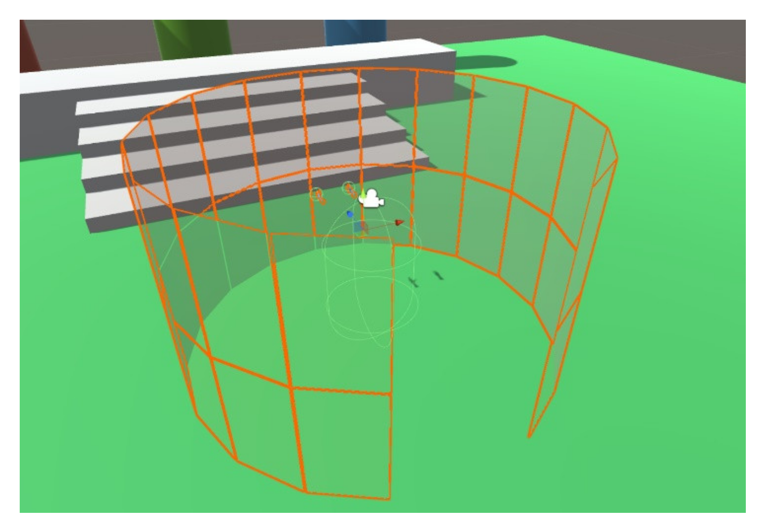
Another key aspect of the API is the ability to simulate controlling the wand controllers on a computer during development (
Figure 20). This gives developers the ability to develop and test their applications without having to physically use Destiny. Below is the diagram of the simulator controls. Much of it was inspired by the original CAVElib simulator developed in 1992 [
28], including the display of projection planes of Destiny within the simulator to help developers gauge whether a virtual object is inside or outside Destiny’s physical volume (
Figure 21). In addition to Destiny’s cylindrical configuration, the CyberCANOE API is also able to support flat wall matrix configurations.
11. Mitigating Stereoscopic Crosstalk
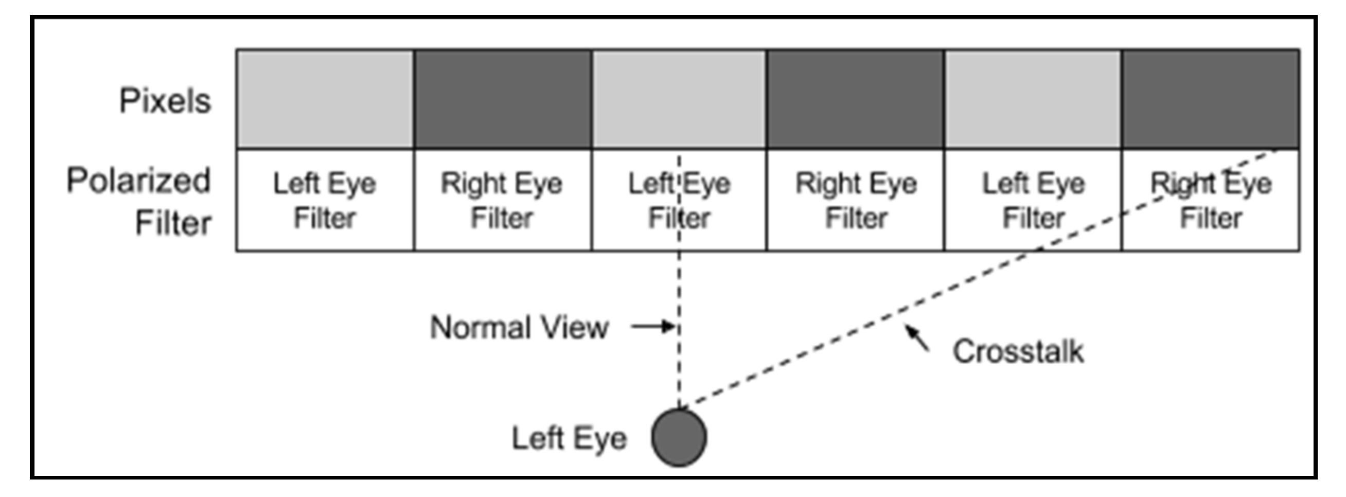
Stereoscopic crosstalk is defined as the incomplete isolation of the left and right image channels so that one image “leaks” or “bleeds” into the other” [
29]. In passive stereo displays, this occurs when a viewer moves off-axis, potentially looking at a pixel through a polarizer intended for the opposite eye as shown in
Figure 22. As the displays in Destiny are oriented in portrait mode, they have excellent vertical off-axis performance but inferior horizontal off-axis performance. CAVE2, using displays in landscape format, mitigates crosstalk via an expensive custom polarizing filter [
30]. The top and bottom rows of the filter are slightly shifted to accommodate a greater vertical off-axis field of view [
1]. It was possible instead to develop an equivalent solution entirely in software, hence significantly reducing cost. A Graphics Processing Unit (GPU) shader was developed to use the location of the viewer’s head in real-time to adjust the pixel color which mitigated the perception of crosstalk.
The GPU shader solution is based on the assumption that crosstalk starts at the intersection of the 3D horizontal FOV and the display column. At this intersection, the user is viewing the intended pixel color, but also the unintended color of the neighboring pixel. Increasing the RGB value of intended pixel color and subtracting the RGB value of the unintended color can potentially counteract the crosstalk effect. However, limitations exist due to using color subtraction. For example, given these pixels:
This technique would not be able to counteract crosstalk as it cannot subtract green from the intended pixel color due to its green channel value being 0.
The following describes the procedure for one display column within Destiny. There are sixteen display columns and each column is calculated separately.
Perpendicular distance (PD) is calculated between the display column and the user’s head. The off-center distance (OCD) is calculated from the display column’s center and the user’s head as shown in
Figure 23.
Given the 3D horizontal FOV is 20 degrees for each display column, it is necessary to calculate which column of pixels the 3D horizontal FOV intersects on the display column and label these left crosstalk starting pixels (LCS) and right crosstalk starting pixels (RCS) (
Figure 24). These two values are passed into a GPU fragment shader.
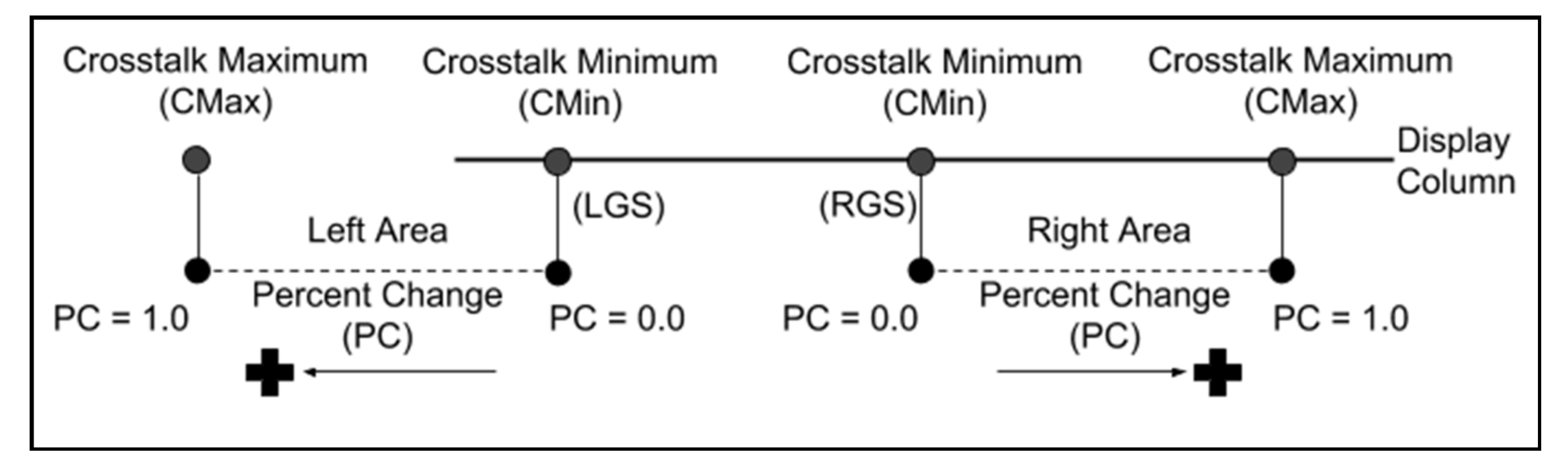
Within the fragment shader the LCS and RCS are used to calculate where the crosstalk starts (CMin) and where the crosstalk stops (CMax). At CMax the user will view a clear picture with no crosstalk but the stereo has been reversed. Pixels closer to CMin will have a smaller percent change (PC) than those closer to CMax. Traversing from CMin to CMax, PC is linearly increased as shown in
Figure 25.
The GPU shader samples intended pixel color (IPC) and the neighbor pixel, which is contributing to the crosstalk pixel color (CPC). The GPU shader then changes the pixel color using one of the following experimental formulas:
Formula 1 (F1)
Formula 2 (F2)
PixelColor.R = ((1 + (PC⋅0.2126))⋅IPC) − ((PC⋅0.2126)⋅CPC)
PixelColor.G = ((1 + (PC⋅0.7152))⋅IPC) − ((PC⋅0.7152)⋅CPC)
PixelColor.B = ((1 + (PC⋅0.0722))⋅IPC) − ((PC⋅0.0722)⋅CPC)
Formula 1 applies the percent change uniformly over the RGB channels while Formula 2 accounts for relative luminance; green light contributing the most to color perceived by humans and blue light the least [
31]. The entire technique is described here, step by step and the two approaches are compared in a subsequent experiment:
- 2.
Calculate the column’s normal with respect to the front.
CN = Normal( (C2 − C1) • (C3 − C1))
- 3.
Obtain the user’s head vector within Destiny.
HL
- 4.
Calculate the perpendicular distance (PD) from the user’s head to the column.
PD = |(HL − CC) • CN|
- 5.
Obtain the column’s rotation and rotate it −90 degrees on the column’s vertical axis.
CR
- 6.
Obtain the vectors of the three corners of the column after rotation.
CR1, CR2, CR3
- 7.
Calculate the column’s normal after rotation.
CRN = Normal ((CR2 − CR1) • (CR3 − CR1))
- 8.
Calculate the off center distance (OCD) from the user’s head to the column’s center.
OCD = (HL − CC) • CRN
- 9.
Calculate the view width.
VW = 2 • (PD) • tan (view angle/2)
- 10.
Obtain the column’s width.
CW
- 11.
Calculate the Left Crosstalk Starting Pixel (LCS).
LCS = ((CW/2) − (VW/2) + OCD)/CW
- 12.
Calculate the Right Crosstalk Starting Pixel (RCS).
RCS = ((CW/2) − (VW/2) + OCD)/CW
- 13.
Within the fragment shader determine if pixel is within left or right crosstalk area.
- 14.
Left area
CMin = LCS − (RCS − LCS)
CMax = LCS
PercentChange = (Pixel.x − CMin)/(CMax − Cmin)
PercentChange = min (MaxPercentChange, 1 − PercentChange)
IPC: Intended Pixel Color
CPC: Crosstalk Pixel Color
- 15.
Apply formula 1 or formula 2 discussed above
- 16.
Right area
- i.
CMin = RCS
- ii.
CMax = RCS + (RCS − LCS)
- iii.
PercentChange = (Pixel.x − CMin)/(CMax − CMin)
- iv.
PercentChange = min (MaxPercentChange, PercentChange)
- v.
IPC: Intended Pixel Color
- vi.
CPC: Crosstalk Pixel Color
- 17.
Apply formula 1 or formula 2 discussed above.
12. Evaluation of Anti-Crosstalk Approaches
The previous section detailed two approaches for mitigating crosstalk. To evaluate these approaches, we conducted an experiment consisting of seven users (aged between 24 and 30). The participants were students in computer science or engineering. All participants reported they had at least 20/20 visual acuity and experience in Hybrid Reality environments.
Each participant wore 3D stereoscopic glasses, a single motion tracked wand, and the motion tracked head visor. All ceiling lights were turned off in the room to reduce distraction and potential interference with the participant.
The experiment involved having each participant standing at a series of 13 locations within Destiny,
Figure 26, and viewing the scene with and without the anti-crosstalk solutions enabled. At each location, the participants were allowed to freely switch between the two options. However, the participants were not informed which of the two options they were viewing. The participants were asked to choose which of the two options they preferred or if they could not decide on a preference. The two options are randomly chosen as the initial choice at random when moving from one location to the next.
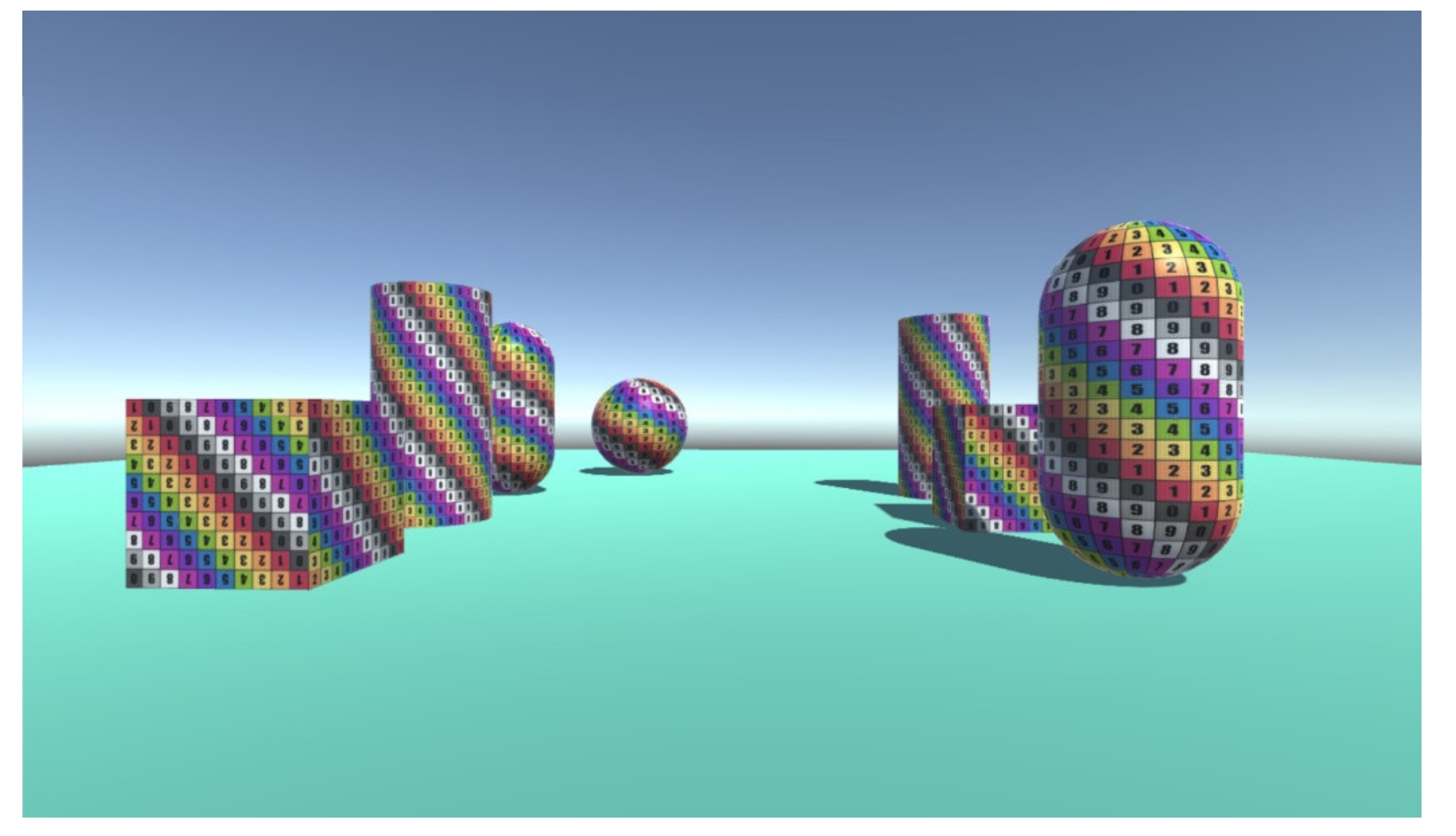
Two different scenes were used. The first scene consisted of simple geometric shapes as shown in
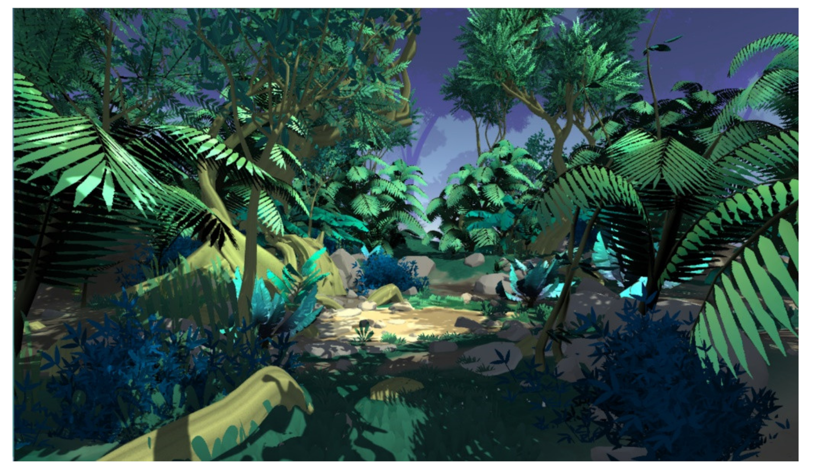
Figure 27 and the second scene consisted of a more naturalistic jungle environment as shown in
Figure 28. The participants performed the test of the first crosstalk formula on the first scene at all 13 locations before proceeding to the second scene. After completing the second scene for the first formula, the participants proceeded to repeat the experiment with the second crosstalk formula.
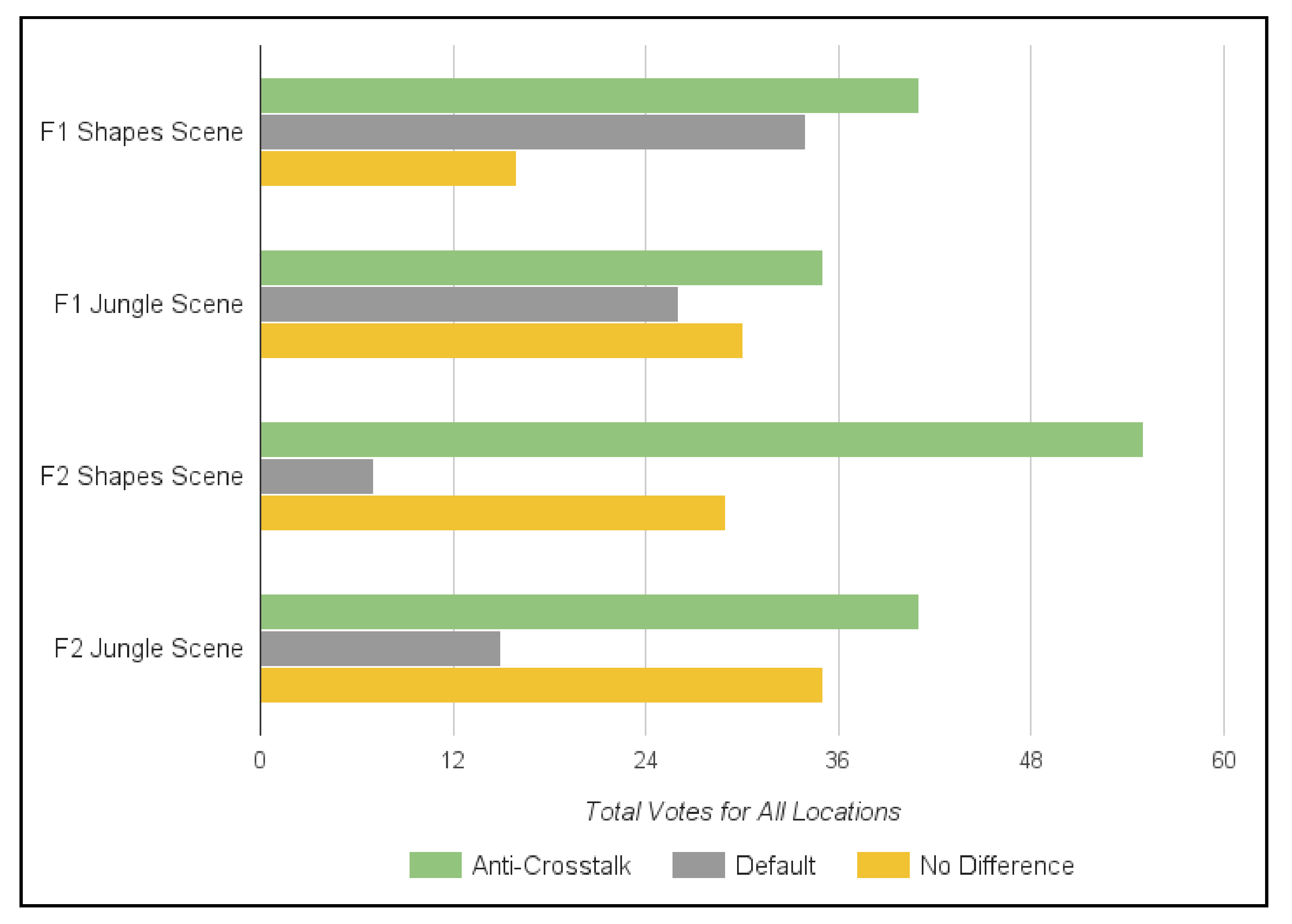
Figure 29 totals the preferences (votes) for the different locations. The results suggest the anti-crosstalk options were preferred over no crosstalk solution in all four tests. Formula 2 (F2) was favored over Formula 1 (F1) for both scenes.
Our results show that having a software-based approach on reducing crosstalk may be a viable alternative to a hardware solution. However, due to the small number of participants, further evaluation is required.
13. Conclusions
This paper’s main contribution is in detailing the design, construction, and evaluation of an OLED-based Hybrid Reality environment with visual acuity approaching 20/20. The HoloLens was found to be useful in its initial design, although its use for construction training needs further study.
The GPU shader approach to crosstalk mitigation was found to be beneficial in a subjective experiment, with the approach that took relative luminance into account yielding better results. Additional experiments similar to the approach by Ponto [
2] are underway to provide a more objective measure of improvement. Plans are also underway to extend the shader approach to resolve pseudo-stereo that occurs at severe off-axis viewing angles.
Author Contributions
Conceptualization, D.K., N.K., R.T., J.L. (Jack Lam) and J.L. (Jason Leigh); methodology, R.T., N.K., and J.L. (Jason Leigh); software, R.T., D.K., E.W., and J.L. (Jack Lam); validation, J.L. (Jason Leigh); formal analysis, R.T. and J.L. (Jason Leigh); investigation, D.K., R.T., T.S.-M. and A.G. (Alberto Gonzalez).; resources, K.N., D.K., R.T., K.U., E.W., and J.L. (Jack Lam); data curation, D.K., N.K., R.T., J.L. (Jack Lam) and J.L. (Jason Leigh); writing—original draft preparation, D.K., T.S.-M., J.L. (Jack Lam) and A.G. (Andrew Guagliardo); writing—review and editing, D.K., R.T. and J.L. (Jason Leigh); visualization, R.T., N.K., and D.K.; supervision, J.L. (Jason Leigh); project administration, J.L. (Jason Leigh); funding acquisition, J.L. (Jason Leigh). All authors have read and agreed to the published version of the manuscript.
Funding
The project is funded in part by the National Science Foundation awards 1456638 and 1530873, and the Academy for Creative Media System (ACM) of the University of Hawai’i.
Informed Consent Statement
Ethical review and approval were waived for this study, due to all subjects being included as authors of the paper.
Conflicts of Interest
The authors declare no conflict of interest.
References
- Febretti, A.; Nishimoto, A.; Thigpen, T.; Talandis, J.; Long, L.; Pirtle, J.D.; Sandin, D. CAVE2: A Hybrid Reality Environment for Immersive Simulation and Information Analysis. Proc. Spie 2013, 8649. [Google Scholar] [CrossRef]
- Ponto, K.; Kohlmann, J.; Tredinnick, R. DSCVR Designing a Commodity Hybrid Virtual Reality System. Virtual Real. 2015, 19, 57–70. [Google Scholar] [CrossRef]
- Knabb, K.A.; Schulze, J.P.; Kuester, F.; DeFanti, T.A.; Levy, T.E. Scientific Visualization, 3D Immersive Virtual Reality Environments, and Archaeology in Jordan and the Near East. Near East. Archaeol. 2014, 77, 228–232. [Google Scholar] [CrossRef]
- HTC Vive. HTC, Vive. Available online: https://www.vive.com/us/ (accessed on 2 December 2020).
- Oculus Rift. Oculus VR, Facebook Inc. Available online: https://www.oculus.com/ (accessed on 2 December 2020).
- Flagship OLED and LCD TV Display Technology Shoot-Out. Available online: https://www.displaymate.com/TV_OLED_LCD_ShootOut_1.htm (accessed on 2 December 2020).
- Johnson, A.; Sandin, D.; Dawe, G.; DeFanti, T.; Pape, D.; Qiu, Z.; Thongrong, S.; Plepys, D. Developing the PARIS: Using the CAVE to Prototype a New VR Display. In Proceedings of the CDROM Proceedings of IPT 2000: Immersive Projection Technology Workshop, Ames, IA, USA, 19–20 June 2000; pp. 19–20. [Google Scholar]
- HoloLens. Microsoft. Available online: https://www.microsoft.com/en-us/hololens (accessed on 2 December 2020).
- 80/20 Inc. Available online: https://8020.net/ (accessed on 2 December 2020).
- AutoCAD. Autodesk. Available online: https://www.autodesk.com/products/autocad (accessed on 2 December 2020).
- OptiTrack Prime 13W. Optitrack. Available online: https://optitrack.com/cameras/prime-13/ (accessed on 2 December 2020).
- DeFanti, T.; Acevedo, D.; Ainsworth, R.; Brown, M.; Cutchin, S.; Dawe, G.; Doerr, K.; Johnson, A.; Knox, C.; Kooima, R. The Future of the CAVE. Open Eng. 2011, 1, 16–37. [Google Scholar] [CrossRef]
- Shi, S.; Hsu, C.-H. A Survey of Interactive Remote Rendering Systems. Acm Comput. Surv. 2015, 47, 1–29. [Google Scholar] [CrossRef]
- Leigh, J.; Johson, A.; Renambot, L.; Peterka, T.; Jeong, B.; Sandin, D.; Talandis, J.; Jagodic, R.; Nam, S.; Hur, H.; et al. Scalable Resolution Display Walls. Proc. IEEE 2013, 101, 115–129. [Google Scholar] [CrossRef]
- Cruz-Neira, C.; Sandin, D.J.; Defanti, T.A. Surround-screen projection-based virtual reality: The design and implementation of the CAVE. In Proceedings of the 20th Annual Conference on Computer Graphics and Interactive Techniques, Anaheim, CA, USA, 2–6 August 1993; pp. 135–142. [Google Scholar] [CrossRef]
- Crus-Neira, C.; Sandin, D.; Defanti, T.; Kenyon, R.V.; Hart, J.C. The CAVE: Audio visual experience. Commun. ACM 1992, 35, 64–73. [Google Scholar] [CrossRef]
- Febretti, A.; Nishimoto, A.; Mateevitsi, V.; Renambot, L.; Johson, A.; Leigh, J. Omegalib: A multi-view application framework for hybrid reality display environments. Virtual Real. IEEE 2014, 9–14. [Google Scholar] [CrossRef]
- Vahdat, A.; Anderson, T.; Dahlin, M.; Belani, E.; Culler, D.; Eastham, P.; Yoshikawa, C. WebOS: Operating system services for wid area applications. In Proceedings of the Seventh International Symposium on High Performance Distributed Computing, Chicago, IL, USA, 28–31 July 1998; pp. 52–63. [Google Scholar]
- Node.js. OpenJS Foundation. Available online: https://nodejs.org/en/ (accessed on 2 December 2020).
- G5 Multi-Touch Screen. PQ Labs. Available online: https://www.pqlabs.com/g5-spec.html (accessed on 2 December 2020).
- Unity. Unity Technologies. Available online: https://unity.com/ (accessed on 2 December 2020).
- Shaw, S.; Green, M.; Liang, J.; Sun, Y. Decoupled simulation in virtual reality with the MR toolkit. ACM Trans. Inf. Syst. 1993, 11, 287–317. [Google Scholar] [CrossRef]
- Park, K.S.; Cho, Y.J.; Krishnaprasad, N.K.; Scharver, C.; Lewis, M.J.; Leigh, J.; Johnson, A.E. CAVERNsoft G2: A toolkit for high performance tele-immersive collaboration. In Proceedings of the ACM Symposium on Virtual Reality Software and Technology (VRST), Hong Kong, China, 11–13 November 2000; pp. 8–15. [Google Scholar] [CrossRef]
- Cruz-Neira, C.; Bierbaum, A.; Hartling, P.; Just, C.; Meinert, K. VR Juggler—An Open Source Platform for Virtual Reality Applications. Virtual Real. IEEE 2001, 89–96. [Google Scholar] [CrossRef]
- Kooima, R. Generalized Perspective Projection. J. Sch. Electron. Eng. Comput. Sci. 2009, 6. [Google Scholar]
- Taylor, R.M., II; Hudson, T.C.; Seeger, A.; Weber, H.; Juliano, J.; Helser, A.T. VRPN: A Device-Independent, Network-Transparent VR Peripheral System. ACM Symp. Virtual Real. Softw. Technol. 2001, 55–61. [Google Scholar] [CrossRef]
- ScpToolKit. Benjamin Höglinger-Stelzer. Available online: https://github.com/nefarius/ScpToolkit (accessed on 2 December 2020).
- Pape, D. A hardware-independent virtual reality development system. IEEE Comput. Graph. Appl. 1996, 16, 44–47. [Google Scholar] [CrossRef]
- Woods, A.J. Understanding Crosstalk in Stereoscopic Displays. In Proceedings of the Keynote Presentation at the Three-Dimensional Systems and Applications Conference, Tokyo, Japan, 19–21 May 2010; pp. 19–21. [Google Scholar]
- Sandin, D.J.; Peterka, T.; Talandis, J.; Leigh, J.; Long, L.; Renambot, L.; Johnson, A.; Brown, M. System and Methods for Visualizing Information (CAVE2). U.S. Patent US 9,800,862B2, 23 October 2017. [Google Scholar]
- Gonzalez, R.C.; Woods, R.E. Digital Image Processing. In Digital Image Processing, 3rd ed.; Prentice Hall: Upper Saddle, NJ, USA, 2007; pp. 352–357. [Google Scholar]
Figure 1.
External view of the Destiny-class CyberCANOE.
Figure 1.
External view of the Destiny-class CyberCANOE.
Figure 2.
The Destiny-class CyberCANOE showing a visualization of coral reef data from the Hawai’i Institute of Marine Biology (data courtesy of John Burns).
Figure 2.
The Destiny-class CyberCANOE showing a visualization of coral reef data from the Hawai’i Institute of Marine Biology (data courtesy of John Burns).
Figure 3.
Top-down view of a portrait-oriented display with 3D 20-degree FOV lines for the left-most and right-most pixel. Minimum 3D viewing distance occurs at the intersection of the two dotted lines.
Figure 3.
Top-down view of a portrait-oriented display with 3D 20-degree FOV lines for the left-most and right-most pixel. Minimum 3D viewing distance occurs at the intersection of the two dotted lines.
Figure 4.
Wireframe design of Destiny in AutoCAD.
Figure 4.
Wireframe design of Destiny in AutoCAD.
Figure 5.
Hologram of the Destiny model as seen through a HoloLens to evaluate its fit within the room’s constraints.
Figure 5.
Hologram of the Destiny model as seen through a HoloLens to evaluate its fit within the room’s constraints.
Figure 6.
A student constructing a column of Destiny utilizing the HoloLens.
Figure 6.
A student constructing a column of Destiny utilizing the HoloLens.
Figure 7.
Step 6 of the Destiny construction manual depicted in the HoloLens on the left, and as a traditional orthographic drawing on the right.
Figure 7.
Step 6 of the Destiny construction manual depicted in the HoloLens on the left, and as a traditional orthographic drawing on the right.
Figure 8.
The 3D printed spacer for supporting the displays.
Figure 8.
The 3D printed spacer for supporting the displays.
Figure 9.
Design of the 3D printed model in AutoDesk Inventor.
Figure 9.
Design of the 3D printed model in AutoDesk Inventor.
Figure 10.
To the left is the dreamGEAR PS3 Move Equalizer shotgun holster. On the right are the Destiny controllers which have replaced the barrel portion with a 3D printed tracking constellation.
Figure 10.
To the left is the dreamGEAR PS3 Move Equalizer shotgun holster. On the right are the Destiny controllers which have replaced the barrel portion with a 3D printed tracking constellation.
Figure 11.
A student using the wands and head tracker in Destiny. A student wearing the three tracked devices (2 wands and head).
Figure 11.
A student using the wands and head tracker in Destiny. A student wearing the three tracked devices (2 wands and head).
Figure 12.
Destiny’s control interface.
Figure 12.
Destiny’s control interface.
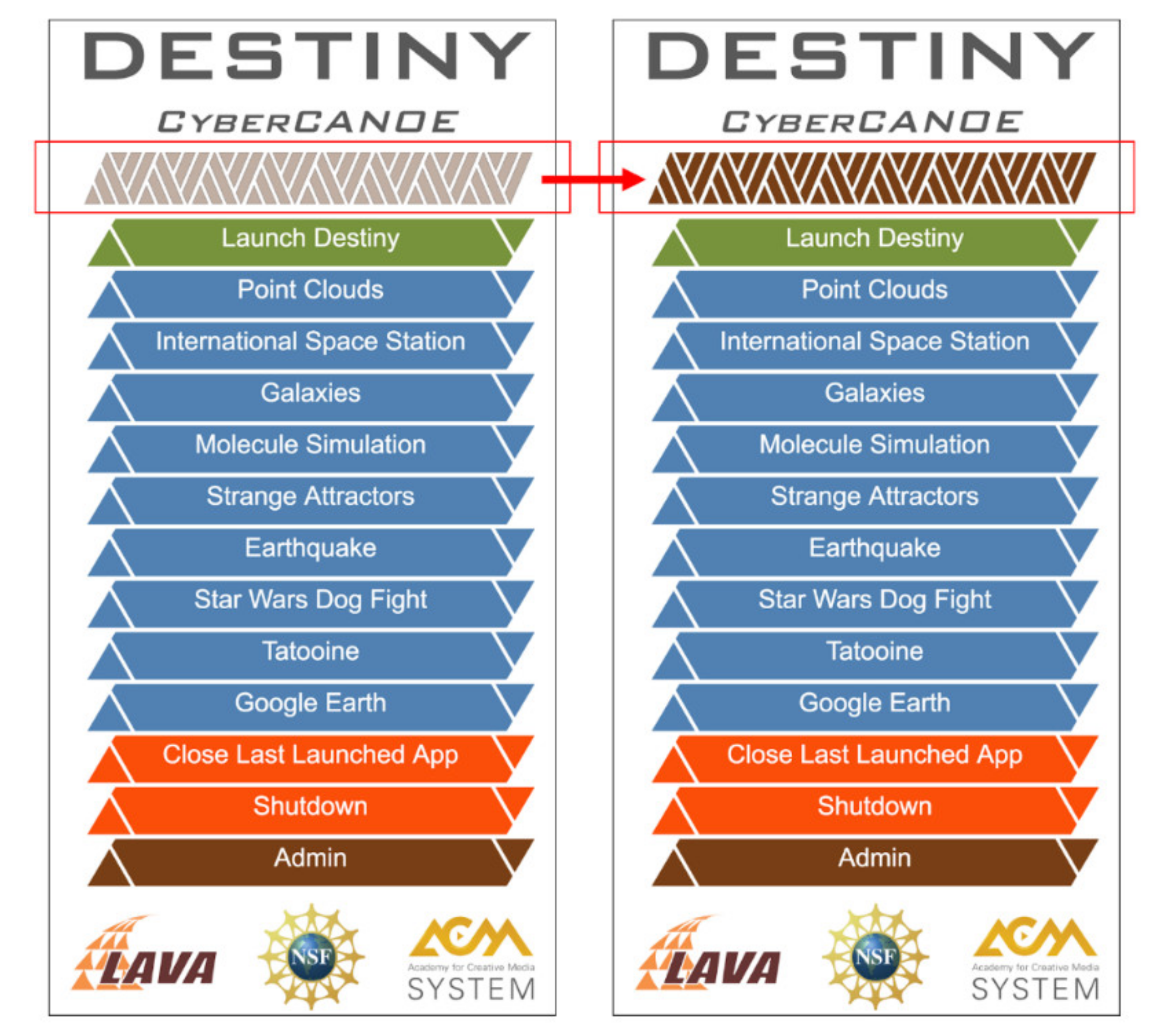
Figure 13.
The glyphs will light up as nodes check into the control computer.
Figure 13.
The glyphs will light up as nodes check into the control computer.
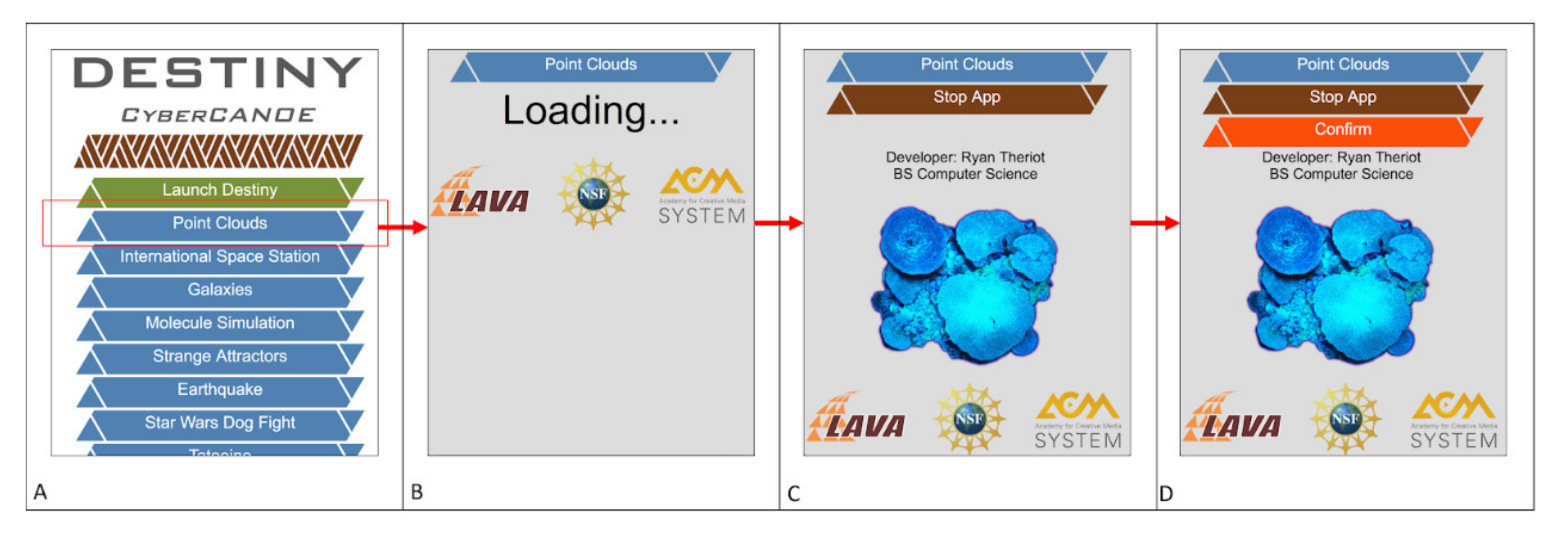
Figure 14.
From the main page, all blue buttons represent applications that can be launched (A). After pressing the Point Clouds button, a loading page will display (B). Once Loaded, some information about the application will be presented and show the button to stop the app (C). To stop the app, first press the Stop App button, to reveal a Confirm button. Pressing the Confirm button will stop the app and return to the main screen (D).
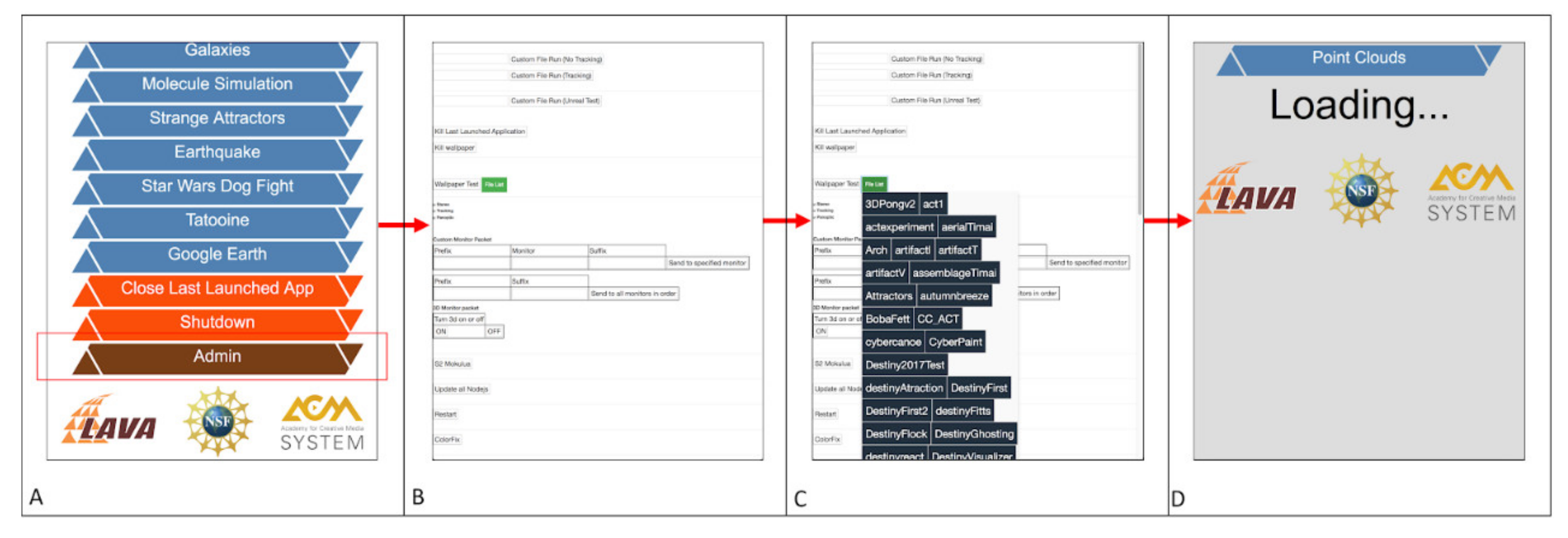
Figure 15.
On the bottom of the main page is the Admin button (A). The admin page presents additional options for launching and sending messages (B). Pressing the File List button will show a list of all apps that have been uploaded (C). Clicking on any of them will swap to the loading screen (D).
Figure 15.
On the bottom of the main page is the Admin button (A). The admin page presents additional options for launching and sending messages (B). Pressing the File List button will show a list of all apps that have been uploaded (C). Clicking on any of them will swap to the loading screen (D).
Figure 16.
To power on Destiny, the following process is repeated for each node. (1) First, the control computer sends a power on signal to each of that node’s displays service port over RS-232. (2) Second, a Wake-On-LAN is sent for that node over Ethernet. (3) Node.js will launch as part of Windows startup, when it will check in with the control computer over WebSocket.
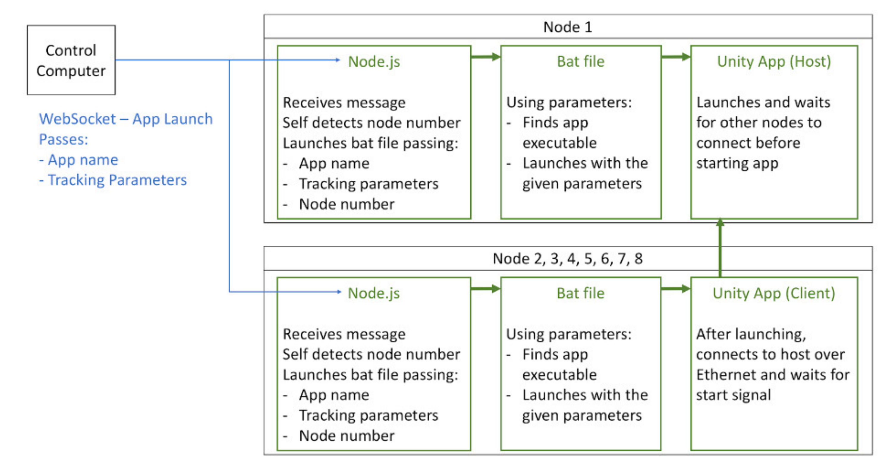
Figure 17.
To launch an application, the control computer sends a message over WebSocket to each node. After receiving the node, they will start the app launching .bat file and pass in the given parameters along with their own node number.
Figure 17.
To launch an application, the control computer sends a message over WebSocket to each node. After receiving the node, they will start the app launching .bat file and pass in the given parameters along with their own node number.
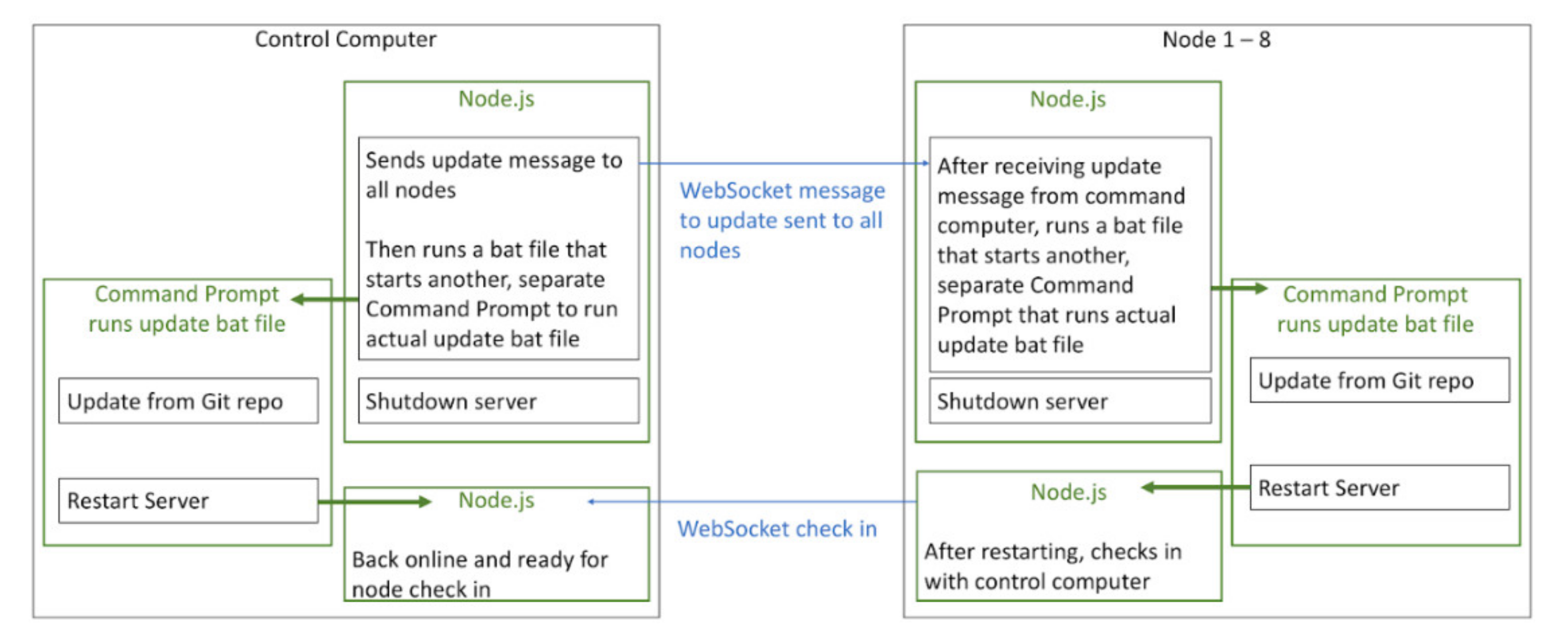
Figure 18.
To update the control system, first the command is initiated through the admin page. After the control computer receives the command, it notifies all other nodes, activates the update .bat file, then shuts itself down. The activated .bat file spawns a separate Command Prompt window to run the real update .bat file. That Command Prompt stays active even after Node.js shuts down. A Git pull is performed from the online repo, and after the pull restarts Nodejs.
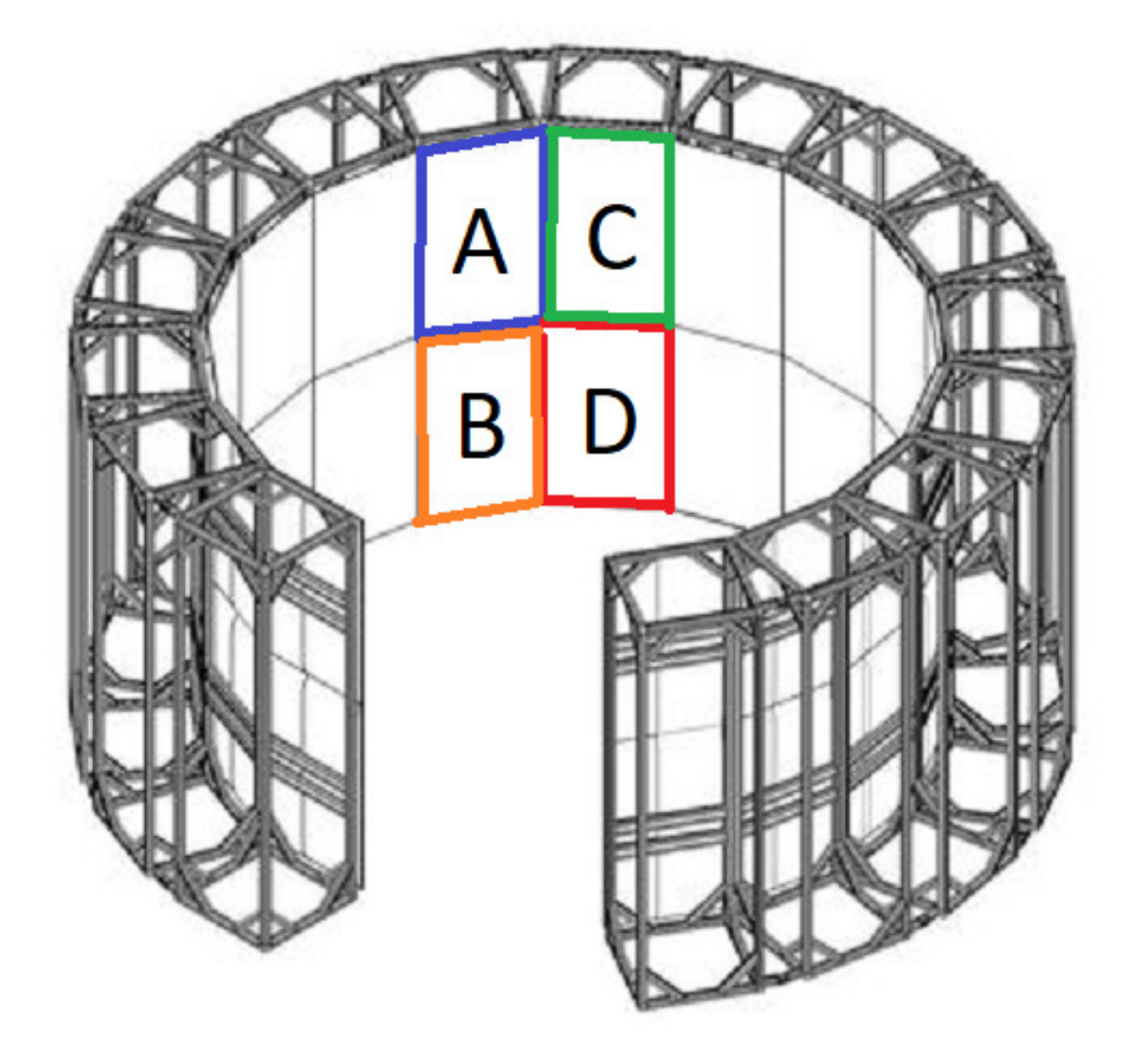
Figure 19.
3D model of Destiny showing four displays (A–D), which are powered by one computer.
Figure 19.
3D model of Destiny showing four displays (A–D), which are powered by one computer.
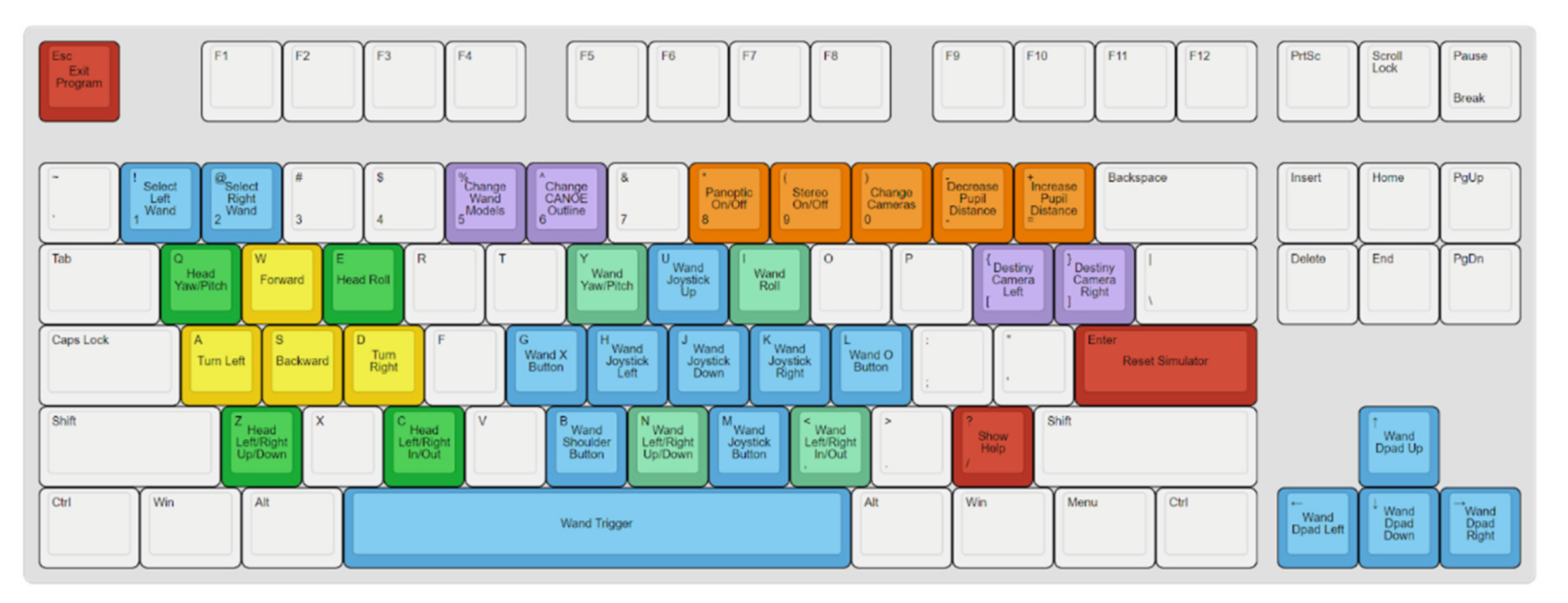
Figure 20.
Controls for manipulating the simulation.
Figure 20.
Controls for manipulating the simulation.
Figure 21.
The API provides highlighting within Unity to show Destiny’s orientation within the scene.
Figure 21.
The API provides highlighting within Unity to show Destiny’s orientation within the scene.
Figure 22.
Off-axis crosstalk.
Figure 22.
Off-axis crosstalk.
Figure 23.
Perpendicular and Off-Center Distance.
Figure 23.
Perpendicular and Off-Center Distance.
Figure 24.
Left and right starting pixel determination.
Figure 24.
Left and right starting pixel determination.
Figure 25.
Crosstalk minimum and maximum within fragment shader.
Figure 25.
Crosstalk minimum and maximum within fragment shader.
Figure 26.
Top-down view of Destiny and the positions used for each evaluation.
Figure 26.
Top-down view of Destiny and the positions used for each evaluation.
Figure 27.
Geometric Shapes Scene.
Figure 27.
Geometric Shapes Scene.
Figure 29.
Comparison of the two anti-crosstalk approaches (F1 and F2) under two different scenes (Shapes Scene and Jungle Scene).
Figure 29.
Comparison of the two anti-crosstalk approaches (F1 and F2) under two different scenes (Shapes Scene and Jungle Scene).
Table 1.
CyberCANOE Class Identification Table.
Table 1.
CyberCANOE Class Identification Table.
| Location | Year | 3D | Megapixels | 6DOF Tracking |
|---|
| UH West Oʻahu | 2014 | Y | 24 | N |
| UHM iLab | 2015 | N | 24 | N |
| UHM LAVA | 2015 | Y | 16 | Y |
| ‘Imiloa Astronomy Center | 2016 | Y | 24 | Y |
| UH Hilo (CS Dept) | 2016 | Y | 24 | N |
| UH Hilo (Art dept) | 2016 | Y | 24 | N |
| UHM LAVA | 2016 | Y | 256 | Y |
| Kamehameha Schools | 2016 | Y | 24 | N |
| Hawaii State Energy Office | 2017 | N | 16 | N |
| UH Hilo (EPSCoR Class) | 2017 | N | 18 | N |
| UHM EPSCoR Laboratory | 2017 | N | 31 | N |
| UH West Oʻahu ‘Ulu’ulu | 2017 | N | 31 | N |
| Chaminade University | 2017 | N | 24 | N |
| Applied Research Lab at UH | 2018 | N | 16 | N |
Table 2.
Acuity Calculator for an LG Model 55EF9500.
Table 2.
Acuity Calculator for an LG Model 55EF9500.
| | Vertical | Horizonal |
|---|
| Screen Dimension | 48.2″ | 27.6″ |
| Stereo Resolution 1 | 3840 | 1080 |
| Angular Resolution 2 | 0.009 | 0.019 |
| Arc Minutes 3 | 0.540 | 1.123 |
| Snellen Notation 4 | 20/11 | 20/22 |
Table 3.
The Destiny System Comparison.
Table 3.
The Destiny System Comparison.
| System | CAVE | CAVE2 | DSCVR | Destiny |
|---|
| Stereo Resolution (MP) 1 | 22.1 | 36.2 | 20.7 | 132.7 |
| Viewable 3D Resolution (MP) 2 | 10.8 | 19.7 | 20.1 | 72.6 |
| FOV Horizontal Coverage (%) 3 | 100 | 100 | 100 | 100 |
| FOV Vertical Coverage (%) 4 | 100 | 27 | 62 | 46.7 |
| Immersive Resolution (MP) 5 | 10.8 | 5.4 | 12.5 | 33.9 |
| Refresh Per Eye (Hz) 6 | 35 | 60 | 60 | 30 |
| Immersive Bandwidth (MP/s) 7 | 378 | 319 | 750 | 1016 |
Table 4.
Communication Parameters.
Table 4.
Communication Parameters.
| Name | Value |
|---|
| Baud Rate | 9600 bps (UART) |
| Stop bit | 1 bit |
| Data length | 8 bits |
| Communication Code | ACSII code |
| Parity | None |
| Transmission | [k][a][ ][Set ID][ ][Data][Cr] |
| Power Off | Data 00 |
| Power On | Data 01 |
| Publisher’s Note: MDPI stays neutral with regard to jurisdictional claims in published maps and institutional affiliations. |
© 2021 by the authors. Licensee MDPI, Basel, Switzerland. This article is an open access article distributed under the terms and conditions of the Creative Commons Attribution (CC BY) license (http://creativecommons.org/licenses/by/4.0/).


