
Review of Electric Vehicle Converter Configurations, Control Schemes and Optimizations: Challenges and Suggestions

 ,
,  , , , ,
  and
and 
Abstract
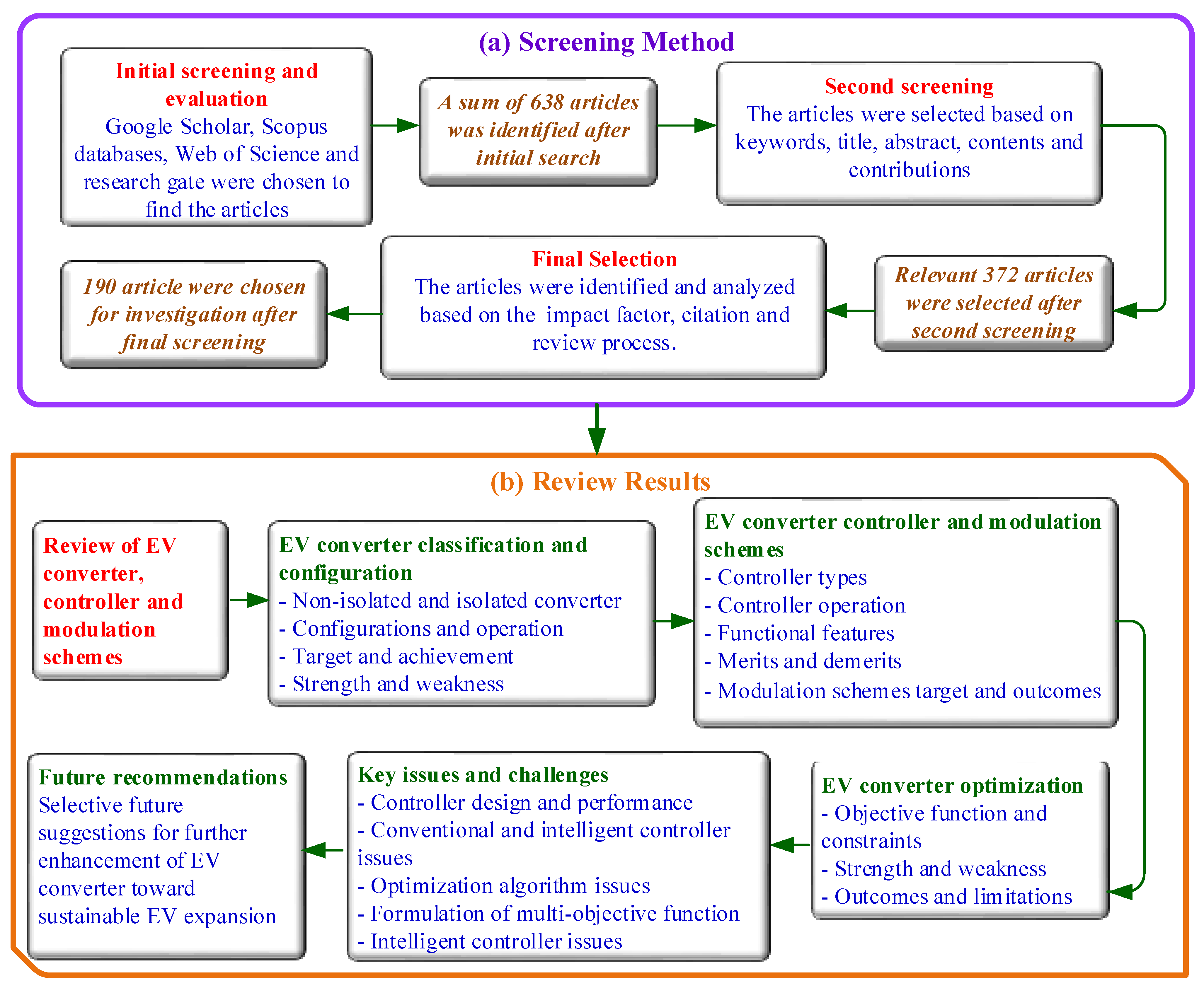
1. Introduction
- A comprehensive explanation of various DC-DC converters for EVs is delivered. In line with that, the classification of EV converters along with their structure, execution process, purpose, achievements, benefits and drawbacks are provided.
- The categories of EV converter controllers, including linear controllers and intelligent controllers, are reported. Besides, the various functional features, control operation, target, contributions, merits and demerits are discussed thoroughly.
- The modulation schemes employed in various controllers in EVs are outlined concerning the target and outcomes.
- The EV converter optimization algorithms with respect to objective functions, constraints, pros and cons are highlighted.
- The existing issues and challenges of EV converters, controllers, modulation and optimization approaches with regard to design, implementation, computational complexity, objective function and performance are explained rigorously.
- Selective future proposals for the design and progress of an efficient converter are delivered.
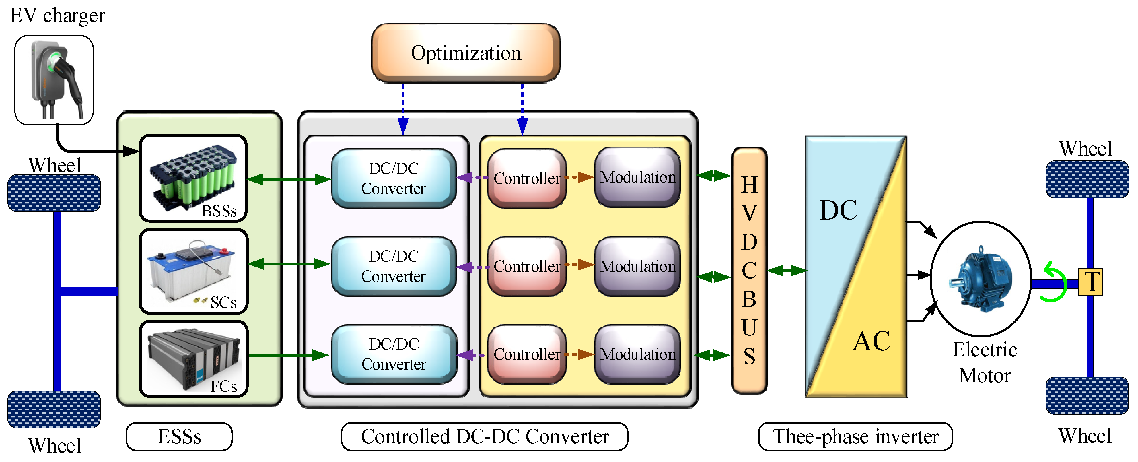
2. Overview of EV Converter Controllers, Modulations and Optimizations
3. EV Converter Types and Configurations
3.1. Non-Isolated Converter
3.1.1. Cuk Converter
3.1.2. Switched-Capacitor Bidirectional Converter
3.1.3. Coupled Inductor Bidirectional Converter
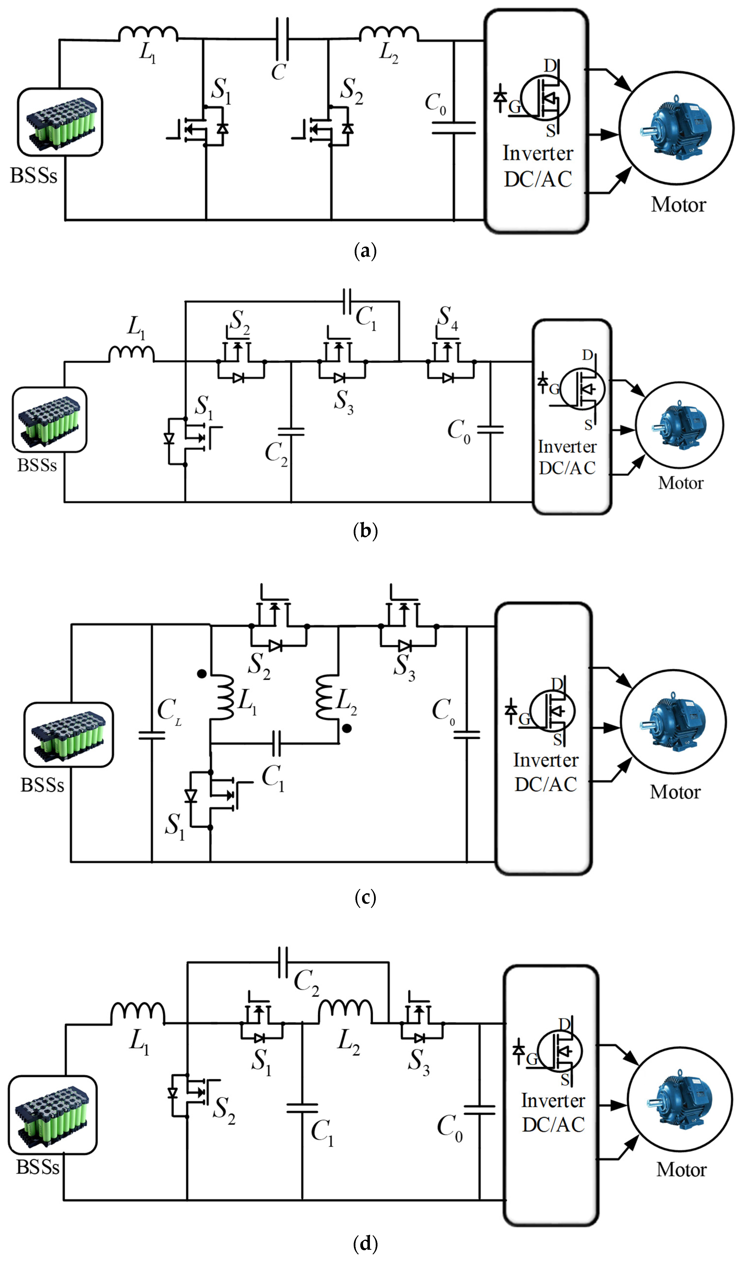
3.1.4. Quasi-Z-Source Bidirectional Converter
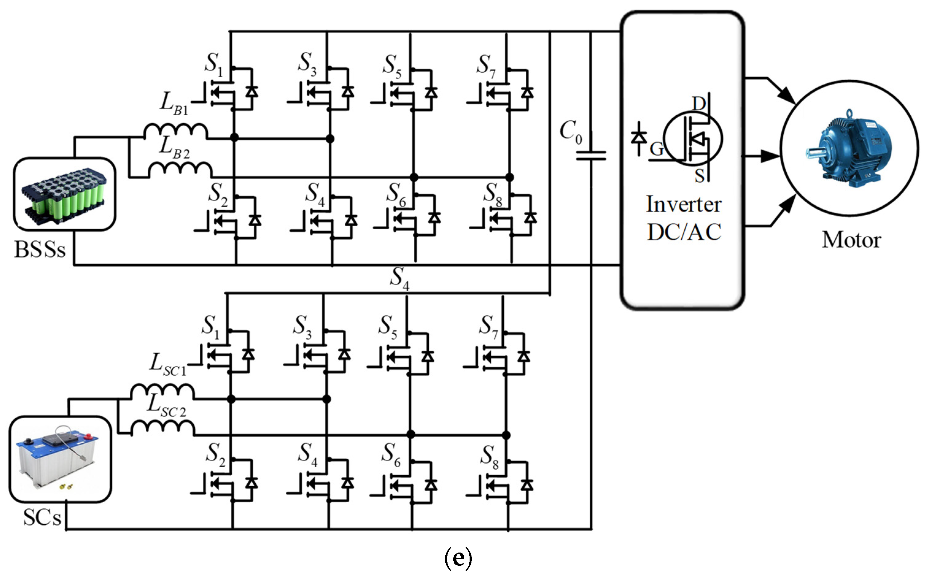
3.1.5. Multi-Device Interleaved Bidirectional Converter
3.2. Isolated Converter
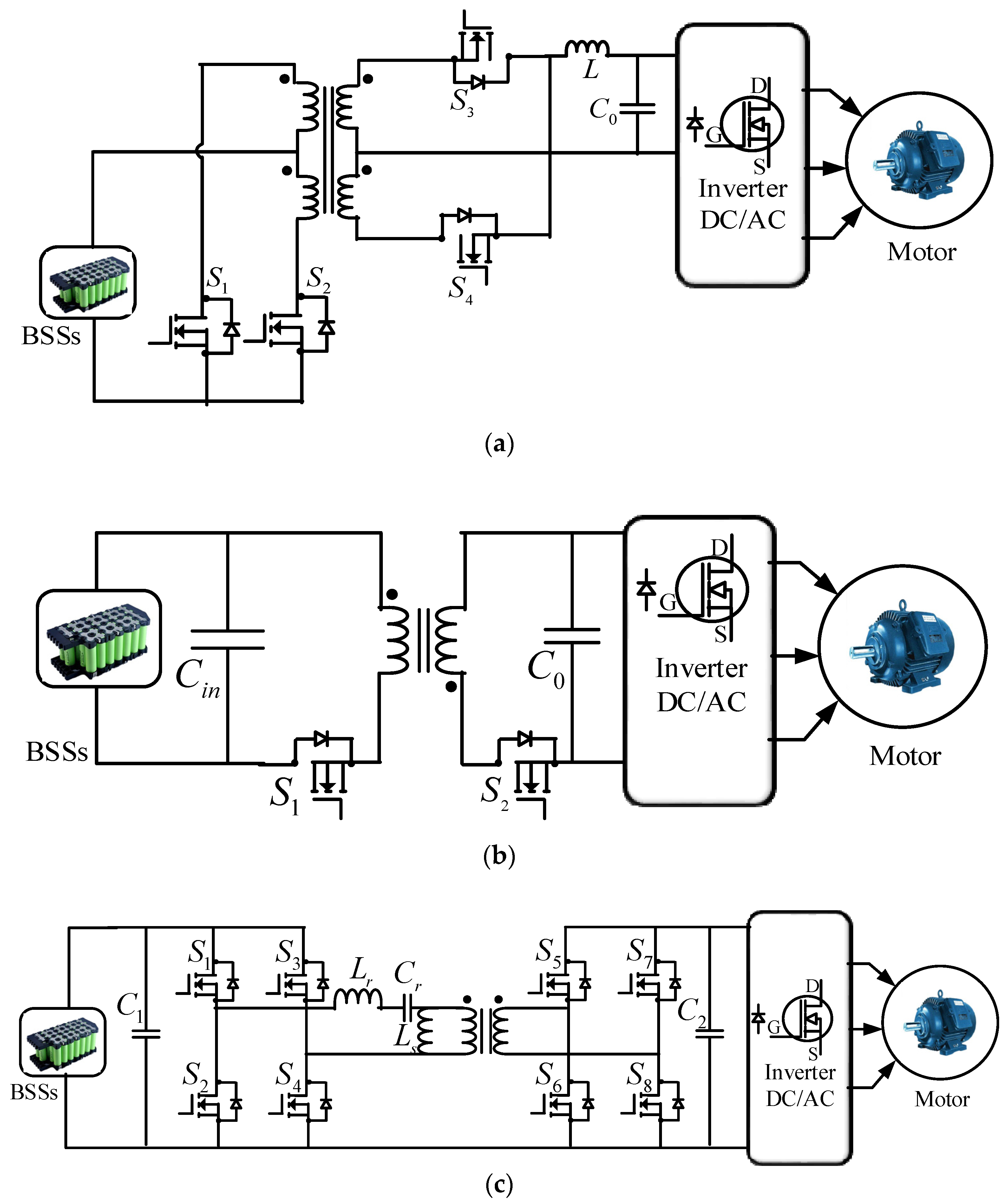
3.2.1. Push–Pull Converter
3.2.2. Flyback Converter
3.2.3. Resonant Converter
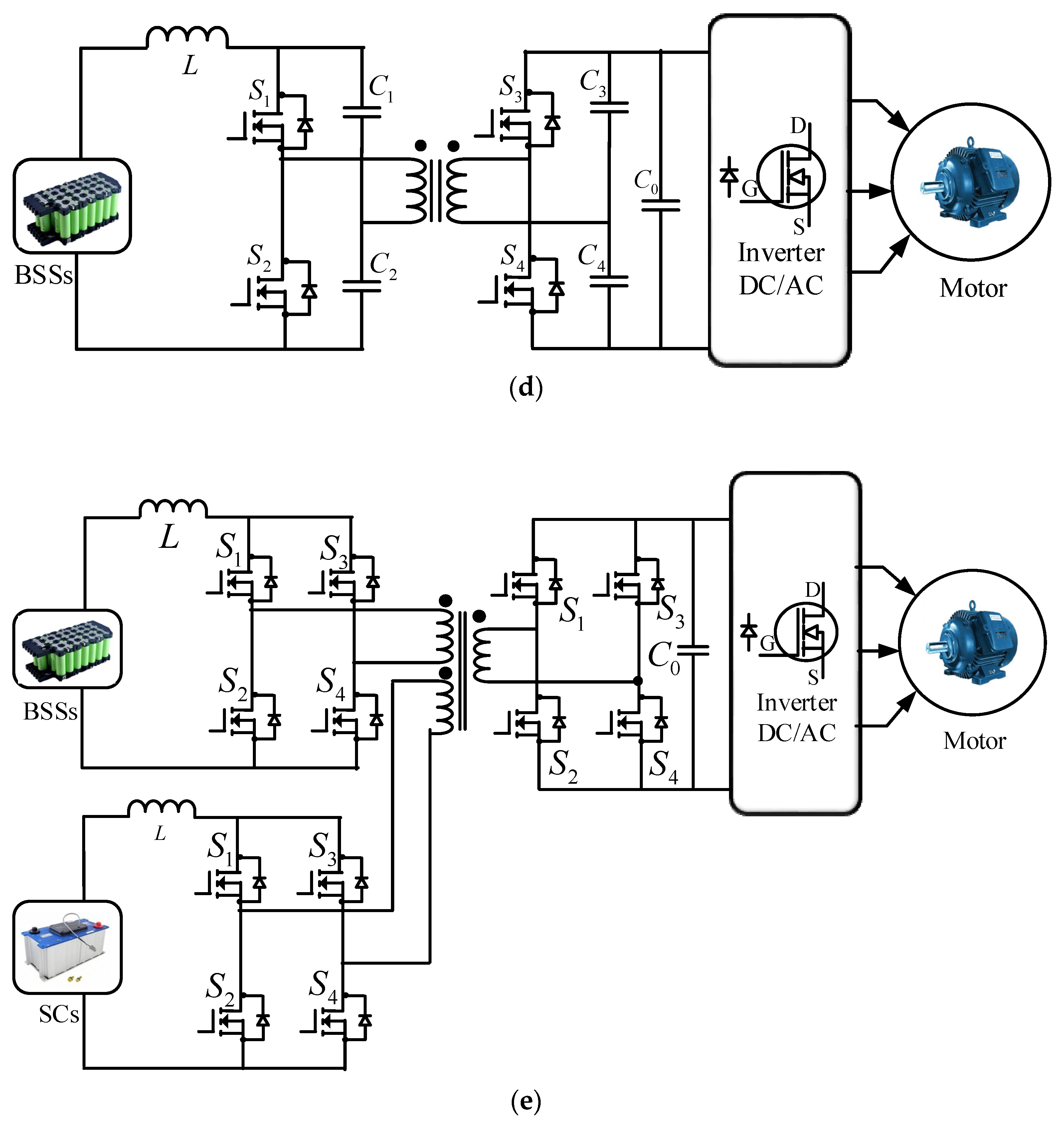
3.2.4. Zero-Voltage Switching Converter
3.2.5. Multi-Port Isolated Converter
4. EV Converter Controller Schemes
4.1. Proportional–Integral Control
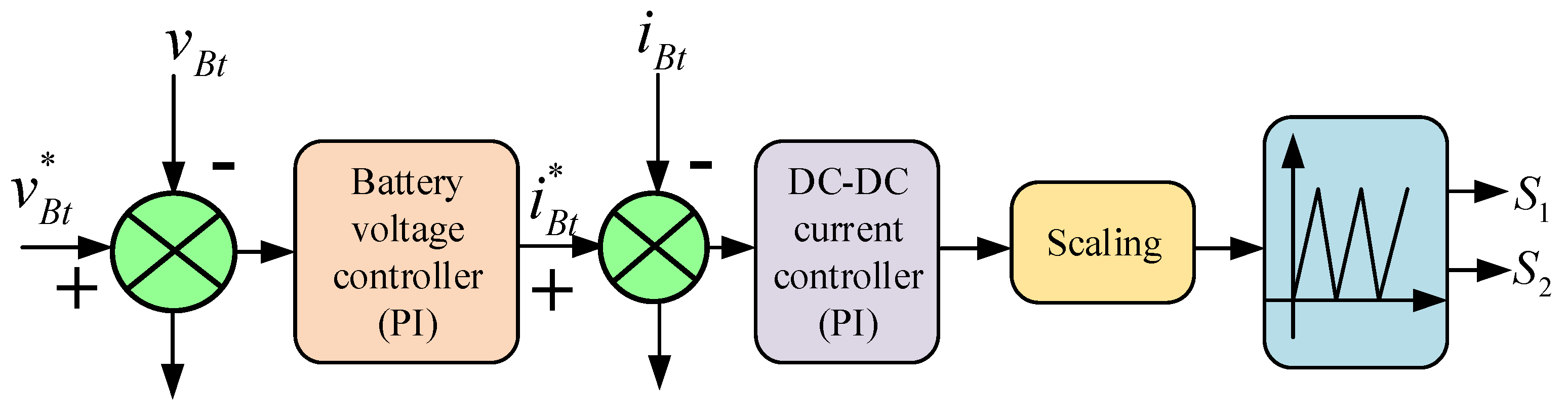
4.1.1. PI Controller in Battery Lifespan Improvement
4.1.2. PI Controller in Stability Improvement of an Integrated Charging System
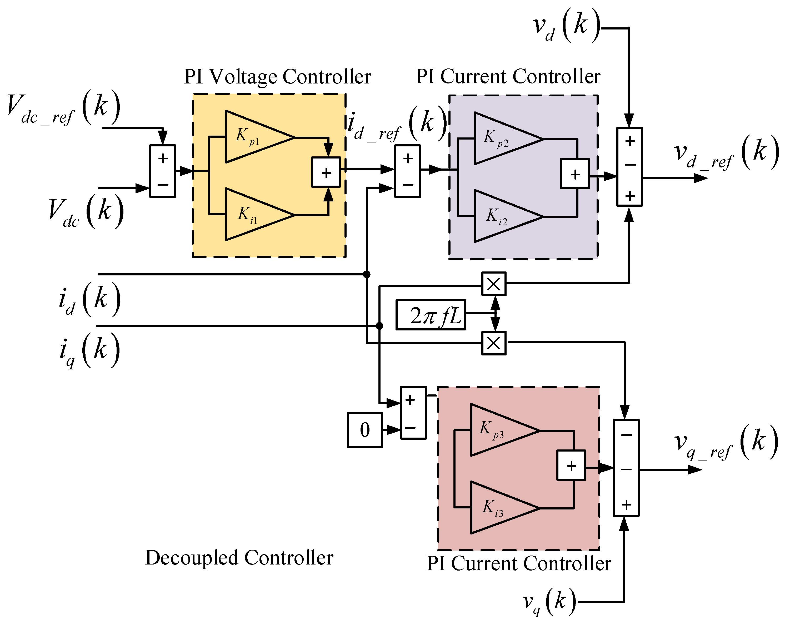
4.1.3. PI Controller in Universal Three-Level Bridge Converter
4.1.4. PI Controller in a Bidirectional Interleaved Hybrid Converter
4.2. Rule-Based Control
4.2.1. Fuzzy Logic Control
4.2.2. Neuro-Fuzzy Logic Control
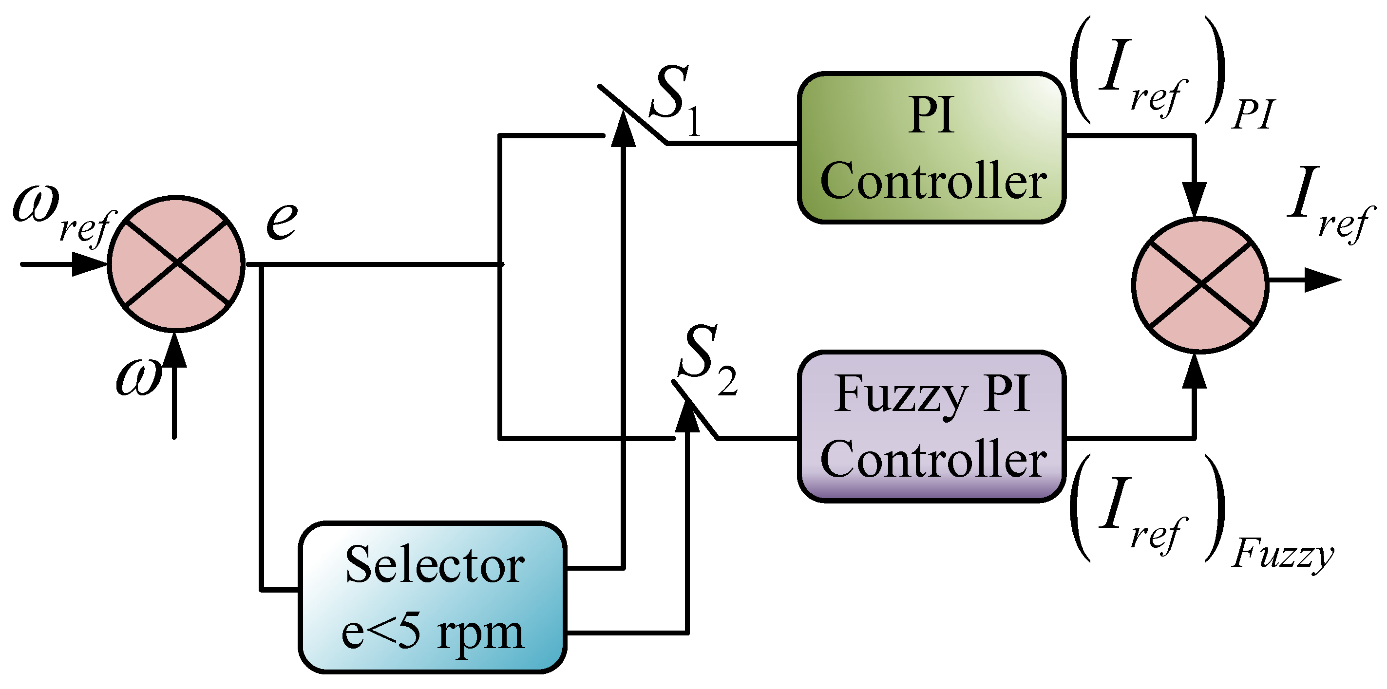
4.2.3. Fuzzy PI Control
4.3. Artificial Neural Network Control
4.4. Sliding Mode Control
4.5. Modulation Techniques in EV Converters
5. EV Converter Optimization Algorithms
5.1. Gradient Algorithms
5.2. Metaheuristic Algorithms
6. Issues and Challenges
6.1. Converter Design and Performance
6.2. Conventional Controller Issues
6.3. Intelligent Controller Issues
6.4. Optimization Algorithm Issues
6.5. Formulation of Multi-Objective Function
6.6. Implementation of the Metaheuristic Algorithm
6.7. Optimized Controller Design
7. Conclusions and Suggestions
- Generally, the converter exhibits high switching loss and power loss in the passive components. Currently, semiconductor materials including silicon carbide (SiC) and gallium nitride (GaN) have become increasingly popular due to their ability to handle high voltage and high current as well as provide high power density with low heat dissipation. However, they have issues of reliability and cost. Thus, future research works should be conducted on the appropriate material selection of the converter that can deliver cost-effective components with a high switching frequency, high reliability and low thermal loss.
- The topologies of the existing converters face problems such as high ripple current, low impedance, low voltage and current stress and sensitive duty cycle. Hence, further exploration is required on electrical design optimization to achieve high frequency and low converter loss under high-temperature conditions. In line with that, further investigation of mechanical design optimization of the converter is required to obtain high reliability, modularity, power density and efficiency.
- The multi-level multi-phase bidirectional converters have drawn attention due to their low current stress, simple control approach and high efficiency. Nonetheless, they need high component counts and complex analysis under steady-state and transient conditions. Besides, the duty cycle is very sensitive under load variation. Thus, it is recommended to focus on building a modular design framework to enable scalability, multi-functionality and high fidelity.
- Intelligent control techniques are useful to control the DC-link voltage and load current as well as achieve bidirectional power management, proper co-ordination of ESSs, fast tracking, fewer steady-state errors and high efficiency. However, they have drawbacks in terms of data integrity, long training operations, expensive processing devices and the need for suitable parameter selection and hyperparameter tuning. Therefore, further investigation is required to address the computational complexity.
- Although optimization algorithms are advantageous toward reducing converter loss, the number of components and cost, their execution in EV converters has been very limited. To date, only GAs and PSO have made decent progress to optimize the design and cost of the converter. Hence, it is suggested to utilize the advanced optimization algorithms in EV converter design.
Author Contributions
Funding
Conflicts of Interest
References
- Hannan, M.A.; Lipu, M.S.H.; Hussain, A.; Mohamed, A. A review of lithium-ion battery state of charge estimation and management system in electric vehicle applications: Challenges and recommendations. Renew. Sustain. Energy Rev. 2017, 78, 834–854. [Google Scholar] [CrossRef]
- Hou, F.; Chen, X.; Chen, X.; Yang, F.; Ma, Z.; Zhang, S.; Liu, C.; Zhao, Y.; Guo, F. Comprehensive analysis method of determining global long-term GHG mitigation potential of passenger battery electric vehicles. J. Clean. Prod. 2020, 125137. [Google Scholar] [CrossRef]
- Ameyaw, B.; Yao, L.; Oppong, A.; Agyeman, J.K. Investigating, forecasting and proposing emission mitigation pathways for CO2 emissions from fossil fuel combustion only: A case study of selected countries. Energy Policy 2019, 130, 7–21. [Google Scholar] [CrossRef]
- Lipu, M.S.H.; Hannan, M.A.; Hussain, A.; Hoque, M.M.; Ker, P.J.; Saad, M.H.M.; Ayob, A. A review of state of health and remaining useful life estimation methods for lithium-ion battery in electric vehicles: Challenges and recommendations. J. Clean. Prod. 2018, 205, 115–133. [Google Scholar] [CrossRef]
- IEA. Tracking Transport 2020. Available online: https://www.iea.org/reports/tracking-transport-2020/electric-vehicles (accessed on 12 September 2020).
- EEA. Greenhouse Gas Emissions from Transport in Europe—European Environment Agency. Available online: https://www.eea.europa.eu/data-and-maps/indicators/transport-emissions-of-greenhouse-gases/transport-emissions-of-greenhouse-gases-12 (accessed on 15 May 2020).
- Hu, Y.; Wang, Z.; Li, X. Impact of policies on electric vehicle diffusion: An evolutionary game of small world network analysis. J. Clean. Prod. 2020, 265, 121703. [Google Scholar] [CrossRef]
- Xue, M.; Lin, B.-L.; Tsunemi, K. Emission implications of electric vehicles in Japan considering energy structure transition and penetration uncertainty. J. Clean. Prod. 2021, 280, 124402. [Google Scholar] [CrossRef]
- Asadi, S.; Nilashi, M.; Samad, S.; Abdullah, R.; Mahmoud, M.; Alkinani, M.H.; Yadegaridehkordi, E. Factors impacting consumers’ intention toward adoption of electric vehicles in Malaysia. J. Clean. Prod. 2020, 282, 124474. [Google Scholar] [CrossRef]
- Feng, S.; An, H.; Li, H.; Qi, Y.; Wang, Z.; Guan, Q.; Li, Y.; Qi, Y. The technology convergence of electric vehicles: Exploring promising and potential technology convergence relationships and topics. J. Clean. Prod. 2020, 260, 120992. [Google Scholar] [CrossRef]
- Chakraborty, S.; Mazuela, M.; Tran, D.D.; Corea-Araujo, J.A.; Lan, Y.; Loiti, A.A.; Garmier, P.; Aizpuru, I.; Hegazy, O. Scalable Modeling Approach and Robust Hardware-in-the-Loop Testing of an Optimized Interleaved Bidirectional HV DC/DC Converter for Electric Vehicle Drivetrains. IEEE Access 2020, 8, 115515–115536. [Google Scholar] [CrossRef]
- Cao, C.; Chen, B. Generalized Nash equilibrium problem based electric vehicle charging management in distribution networks. Int. J. Energy Res. 2018, 42, 4584–4596. [Google Scholar] [CrossRef]
- Ding, X.; Wang, Z.; Zhang, L.; Wang, C. Longitudinal Vehicle Speed Estimation for Four-Wheel-Independently-Actuated Electric Vehicles Based on Multi-Sensor Fusion. IEEE Trans. Veh. Technol. 2020, 69, 12797–12806. [Google Scholar] [CrossRef]
- Zhang, L.; Wang, Y.; Wang, Z. Robust Lateral Motion Control for In-Wheel-Motor-Drive Electric Vehicles with Network Induced Delays. IEEE Trans. Veh. Technol. 2019, 68, 10585–10593. [Google Scholar] [CrossRef]
- Hannan, M.A.; Lipu, M.S.H.; Ker, P.J.; Begum, R.A.; Agelidis, V.G.; Blaabjerg, F. Power electronics contribution to renewable energy conversion addressing emission reduction: Applications, issues, and recommendations. Appl. Energy 2019, 251, 113404. [Google Scholar] [CrossRef]
- Miri, I.; Fotouhi, A.; Ewin, N. Electric vehicle energy consumption modelling and estimation—A case study. Int. J. Energy Res. 2020, 5700. [Google Scholar] [CrossRef]
- Javorski Eckert, J.; Corrêa de Alkmin e Silva, L.; Mazzariol Santiciolli, F.; dos Santos Costa, E.; Corrêa, F.C.; Giuseppe Dedini, F. Energy storage and control optimization for an electric vehicle. Int. J. Energy Res. 2018, 42, 3506–3523. [Google Scholar] [CrossRef]
- Wu, J.; Wu, Z.; Wu, F.; Mao, X. A power balancing method of distributed generation and electric vehicle charging for minimizing operation cost of distribution systems with uncertainties. Energy Sci. Eng. 2017, 5, 167–179. [Google Scholar] [CrossRef]
- Manzetti, S.; Mariasiu, F. Electric vehicle battery technologies: From present state to future systems. Renew. Sustain. Energy Rev. 2015, 51, 1004–1012. [Google Scholar] [CrossRef]
- Pollet, B.G.; Staffell, I.; Shang, J.L. Current status of hybrid, battery and fuel cell electric vehicles: From electrochemistry to market prospects. Electrochim. Acta 2012, 84, 235–249. [Google Scholar] [CrossRef]
- Moura, S.J.; Fathy, H.K.; Callaway, D.S.; Stein, J.L. A stochastic optimal control approach for power management in plug-in hybrid electric vehicles. IEEE Trans. Control. Syst. Technol. 2011, 19, 545–555. [Google Scholar] [CrossRef]
- Zhai, L.; Hu, G.; Lv, M.; Zhang, T.; Hou, R. Comparison of Two Design Methods of EMI Filter for High Voltage Power Supply in DC-DC Converter of Electric Vehicle. IEEE Access 2020, 8, 66564–66577. [Google Scholar] [CrossRef]
- Gomez Navarro, F.J.; Yebra, L.J.; Gomez Medina, F.J.; Gimenez-Fernandez, A. DC-DC Linearized Converter Model for Faster Simulation of Lightweight Urban Electric Vehicles. IEEE Access 2020, 8, 85380–85394. [Google Scholar] [CrossRef]
- Elsayad, N.; Moradisizkoohi, H.; Mohammed, O.A. A New Hybrid Structure of a Bidirectional DC-DC Converter with High Conversion Ratios for Electric Vehicles. IEEE Trans. Veh. Technol. 2020, 69, 194–206. [Google Scholar] [CrossRef]
- Zhang, L.; Hu, X.; Wang, Z.; Ruan, J.; Ma, C.; Song, Z.; Dorrell, D.G.; Pecht, M.G. Hybrid electrochemical energy storage systems: An overview for smart grid and electrified vehicle applications. Renew. Sustain. Energy Rev. 2020, 110581. [Google Scholar] [CrossRef]
- Lai, C.M.; Cheng, Y.H.; Hsieh, M.H.; Lin, Y.C. Development of a Bidirectional DC/DC Converter with Dual-Battery Energy Storage for Hybrid Electric Vehicle System. IEEE Trans. Veh. Technol. 2018, 67, 1036–1052. [Google Scholar] [CrossRef]
- Kanamarlapudi, V.R.K.; Wang, B.; Kandasamy, N.K.; So, P.L. A New ZVS Full-Bridge DC-DC Converter for Battery Charging with Reduced Losses Over Full-Load Range. IEEE Trans. Ind. Appl. 2018, 54, 571–579. [Google Scholar] [CrossRef]
- Fardahar, S.M.; Sabahi, M. New Expandable Switched-Capacitor/Switched-Inductor High-Voltage Conversion Ratio Bidirectional DC-DC Converter. IEEE Trans. Power Electron. 2020, 35, 2480–2487. [Google Scholar] [CrossRef]
- Sayed, K. Zero-voltage soft-switching DC-DC converterbased charger for LV battery in hybrid electric vehicles. IET Power Electron. 2019, 12, 3389–3396. [Google Scholar] [CrossRef]
- Moradisizkoohi, H.; Elsayad, N.; Mohammed, O.A. Experimental Verification of a Double-Input Soft-Switched DC-DC Converter for Fuel Cell Electric Vehicle with Hybrid Energy Storage System. IEEE Trans. Ind. Appl. 2019, 55, 6451–6465. [Google Scholar] [CrossRef]
- Lei, J.; Zhou, B.; Wei, J.; Bian, J.; Zhu, Y.; Yu, J.; Yang, Y. Predictive Power Control of Matrix Converter with Active Damping Function. IEEE Trans. Ind. Electron. 2016, 63, 4550–4559. [Google Scholar] [CrossRef]
- Thirumalaivasan, R.; Xu, Y.; Janaki, M. Power control with z-source converter based unified power flow controller. IEEE Trans. Power Electron. 2017, 32, 9413–9423. [Google Scholar] [CrossRef]
- Pedroso, M.D.; Nascimento, C.B.; Tusset, A.M.; Kaster, M.D.S. Performance comparison between nonlinear and linear controllers with weighted adaptive control applied to a buck converter using poles placement design. In Proceedings of the International Symposium on Industrial Electronics, Taiwan, China, 28–31 May 2013; Institute of Electrical and Electronics Engineers Inc.: New York, NY, USA; pp. 1–6. [Google Scholar]
- Bhat, V.S.; Kumar, V.; Dayanand, N.; Shettigar, A.; Nikhitha. Comparative study of PID control algorithms for an electric vehicle. In Proceedings of the AIP Conference Proceedings, Jaipur, India, 5–6 March 2020; American Institute of Physics Inc.: College Park, MD, USA, 2020; Volume 2236, p. 80001. [Google Scholar]
- Babaei, F.; Lashkari, Z.B.; Safari, A.; Farrokhifar, M.; Salehi, J. Salp swarm algorithm-based fractional-order PID controller for LFC systems in the presence of delayed EV aggregators. IET Electr. Syst. Transp. 2020, 10, 259–267. [Google Scholar] [CrossRef]
- Hannan, M.A.; Ali, J.A.; Ker, P.J.; Mohamed, A.; Lipu, M.S.H.; Hussain, A. Switching Techniques and Intelligent Controllers for Induction Motor Drive: Issues and Recommendations. IEEE Access 2018, 6, 47489–47510. [Google Scholar] [CrossRef]
- Hannan, M.A.; Islam, N.N.; Mohamed, A.; Lipu, M.S.H.; Ker, P.J.; Rashid, M.M.; Shareef, H. Artificial Intelligent Based Damping Controller Optimization for the Multi-Machine Power System: A Review. IEEE Access 2018, 6, 39574–39594. [Google Scholar] [CrossRef]
- Parra, A.; Zubizarreta, A.; Pérez, J.; Dendaluce, M. Intelligent Torque Vectoring Approach for Electric Vehicles with Per-Wheel Motors. Complexity 2018, 2018, 1–15. [Google Scholar] [CrossRef]
- Hassan, S.; Kamal, T.; Riaz, M.; Shah, S.; Ali, H.; Riaz, M.; Sarmad, M.; Zahoor, A.; Khan, M.; Miqueleiz, J. Intelligent Control of Wind-Assisted PHEVs Smart Charging Station. Energies 2019, 12, 909. [Google Scholar] [CrossRef]
- Pérez-Pimentel, Y.; Osuna-Galán, I.; Avilés-Cruz, C.; Villegas-Cortez, J. Power supply management for an electric vehicle using fuzzy logic. Appl. Comput. Intell. Soft Comput. 2018, 2018, 1–9. [Google Scholar] [CrossRef]
- Yao, E.; Liu, T.; Lu, T.; Yang, Y. Optimization of electric vehicle scheduling with multiple vehicle types in public transport. Sustain. Cities Soc. 2020, 52, 101862. [Google Scholar] [CrossRef]
- Shen, Z.J.M.; Feng, B.; Mao, C.; Ran, L. Optimization models for electric vehicle service operations: A literature review. Transp. Res. Part. B Methodol. 2019, 128, 462–477. [Google Scholar] [CrossRef]
- Nguyen, D.-D.; Bui, N.-T.; Yukita, K. Design and optimization of three-phase dual-active-bridge converters for electric vehicle charging stations. Energies 2020, 13, 150. [Google Scholar] [CrossRef]
- Aymen, F.; Mahmoudi, C. A novel energy optimization approach for electrical vehicles in a smart city. Energies 2019, 12, 929. [Google Scholar] [CrossRef]
- Chakraborty, S.; Vu, H.-N.; Hasan, M.M.; Tran, D.-D.; Baghdadi, M.E.; Hegazy, O. DC-DC Converter Topologies for Electric Vehicles, Plug-in Hybrid Electric Vehicles and Fast Charging Stations: State of the Art and Future Trends. Energies 2019, 12, 1569. [Google Scholar] [CrossRef]
- Jagadeesh, I.; Indragandhi, V. Review and comparative analysis on dc-dc converters used in electric vehicle applications. In Proceedings of the IOP Conference Series: Materials Science and Engineering, Bangkok, Thailand, 17–19 May 2019; Institute of Physics Publishing: Bristol, UK, 2019; Volume 623, p. 12005. [Google Scholar]
- Bellur, D.M.; Kazimierczuk, M.K. DC-DC converters for electric vehicle applications. In Proceedings of the 2007 Electrical Insulation Conference and Electrical Manufacturing Expo, Nashville, TN, USA, 22–24 October 2007; pp. 286–293. [Google Scholar]
- Anbazhagan, L.; Ramiah, J.; Krishnaswamy, V.; Jayachandran, D.N. A comprehensive Review on Bidirectional Traction Converter for Electric Vehicles. Int. J. Electron. Telecommun. 2019, 65, 635–649. [Google Scholar] [CrossRef]
- Krithika, V.; Subramani, C. A comprehensive review on choice of hybrid vehicles and power converters, control strategies for hybrid electric vehicles. Int. J. Energy Res. 2018, 42, 1789–1812. [Google Scholar] [CrossRef]
- Kumar, D.; Nema, R.K.; Gupta, S. A comparative review on power conversion topologies and energy storage system for electric vehicles. Int. J. Energy Res. 2020, 44, 7863–7885. [Google Scholar] [CrossRef]
- Lipu, M.S.H.; Hannan, M.A.; Hussain, A.; Saad, M.H.M.; Ayob, A.; Uddin, M. Extreme Learning Machine Model for State of Charge Estimation of Lithium-ion battery Using Gravitational Search Algorithm. IEEE Trans. Ind. Appl. 2019, 55, 4225–4234. [Google Scholar] [CrossRef]
- Liu, Y.; Huang, Z.; Liao, H.; Lyu, C.; Zhou, Y.; Jiao, Y.; Li, H.; Hu, C.; Peng, J. A Temperature-Suppression Charging Strategy for Supercapacitor Stack with Lifetime Maximization. IEEE Trans. Ind. Appl. 2019, 55, 6173–6183. [Google Scholar] [CrossRef]
- Mukherjee, N.; Strickland, D. Control of Cascaded DC-DC Converter-Based Hybrid Battery Energy Storage Systems-Part I: Stability Issue. IEEE Trans. Ind. Electron. 2016, 63, 2340–2349. [Google Scholar] [CrossRef]
- Wang, Y.X.; Yu, D.H.; Chen, S.A.; Kim, Y.B. Robust DC/DC converter control for polymer electrolyte membrane fuel cell application. J. Power Sources 2014, 261, 292–305. [Google Scholar] [CrossRef]
- Ma, X.; Wang, P.; Bi, H.; Wang, Z. A Bidirectional LLCL Resonant DC-DC Converter with Reduced Resonant Tank Currents and Reduced Voltage Stress of the Resonant Capacitor. IEEE Access 2020, 8, 125549–125564. [Google Scholar] [CrossRef]
- Fardoun, A.A.; Ismail, E.H.; Sabzali, A.J.; Al-Saffar, M.A. Bidirectional converter for high-efficiency fuel cell powertrain. J. Power Sources 2014, 249, 470–482. [Google Scholar] [CrossRef]
- Dotelli, G.; Ferrero, R.; Gallo Stampino, P.; Latorrata, S.; Toscani, S. Supercapacitor Sizing for Fast Power Dips in a Hybrid Supercapacitor-PEM Fuel Cell System. IEEE Trans. Instrum. Meas. 2016, 65, 2196–2203. [Google Scholar] [CrossRef]
- Kasicheyanula, S.; John, V. Adaptive Control Strategy for Ultracapacitor Based Bidirectional DC-DC Converters. IEEE Trans. Ind. Appl. 2019, 55, 1717–1728. [Google Scholar] [CrossRef]
- Gorji, S.A.; Sahebi, H.G.; Ektesabi, M.; Rad, A.B. Topologies and control schemes of bidirectional DC–DC power converters: An overview. IEEE Access 2019, 7, 117997–118019. [Google Scholar] [CrossRef]
- Maroti, P.K.; Padmanaban, S.; Blaabjerg, F.; Fedák, V.; Siano, P.; Ramachandaramurthy, V.K. A novel switched inductor configuration for modified SEPIC DC-to-DC converter for renewable energy application. In Proceedings of the IEEE Conference on Energy Conversion, Kuala Lumpur, Malaysia, 30–31 October 2017; Institute of Electrical and Electronics Engineers Inc.: New York, NY, USA, 2017; pp. 218–223. [Google Scholar]
- Liu, H.; Dahidah, M.S.A.; Yu, J.; Naayagi, R.T.; Armstrong, M. Design and Control of Unidirectional DC-DC Modular Multilevel Converter for Offshore DC Collection Point: Theoretical Analysis and Experimental Validation. IEEE Trans. Power Electron. 2019, 34, 5191–5208. [Google Scholar] [CrossRef]
- Zahid, Z.U.; Dalala, Z.M.; Chen, R.; Chen, B.; Lai, J.S. Design of bidirectional DC-DC resonant converter for Vehicle-to-Grid (V2G) applications. IEEE Trans. Transp. Electrif. 2015, 1, 232–244. [Google Scholar] [CrossRef]
- Ananthapadmanabha, B.R.; Maurya, R.; Arya, S.R. Improved Power Quality Switched Inductor Cuk Converter for Battery Charging Applications. IEEE Trans. Power Electron. 2018, 33, 9412–9423. [Google Scholar] [CrossRef]
- Shaneh, M.; Adib, E.; Niroomand, M. An Ultrahigh Step-Up Nonisolated Interleaved Converter with Low Input Current Ripple. IEEE J. Emerg. Sel. Top. Power Electron. 2020, 8, 1584–1592. [Google Scholar] [CrossRef]
- Hu, X.; Ma, P.; Wang, J.; Tan, G. A Hybrid Cascaded DC-DC Boost Converter with Ripple Reduction and Large Conversion Ratio. IEEE J. Emerg. Sel. Top. Power Electron. 2020, 8, 761–770. [Google Scholar] [CrossRef]
- Ardi, H.; Ajami, A. Study on a High Voltage Gain SEPIC-Based DC-DC Converter with Continuous Input Current for Sustainable Energy Applications. IEEE Trans. Power Electron. 2018, 33, 10403–10409. [Google Scholar] [CrossRef]
- Azizkandi, M.E.; Sedaghati, F.; Shayeghi, H.; Blaabjerg, F. A High Voltage Gain DC-DC Converter Based on Three Winding Coupled Inductor and Voltage Multiplier Cell. IEEE Trans. Power Electron. 2020, 35, 4558–4567. [Google Scholar] [CrossRef]
- Shreelakshmi, M.P.; Das, M.; Agarwal, V. Design and Development of a Novel High Voltage Gain, High-Efficiency Bidirectional DC-DC Converter for Storage Interface. IEEE Trans. Ind. Electron. 2019, 66, 4490–4501. [Google Scholar] [CrossRef]
- Li, W.; Jiang, Q.; Mei, Y.; Li, C.; Deng, Y.; He, X. Modular multilevel DC/DC converters with phase-shift control scheme for high-voltage DC-based systems. IEEE Trans. Power Electron. 2015, 30, 99–107. [Google Scholar] [CrossRef]
- Jin, K.; Liu, C. A Novel PWM High Voltage Conversion Ratio Bidirectional Three-Phase DC/DC Converter with Y-Δ Connected Transformer. IEEE Trans. Power Electron. 2016, 31, 81–88. [Google Scholar] [CrossRef]
- Bandeira, D.G.; Lazzarin, T.B.; Barbi, I. High Voltage Power Supply Using a T-Type Parallel Resonant DC-DC Converter. IEEE Trans. Ind. Appl. 2018, 54, 2459–2470. [Google Scholar] [CrossRef]
- Turksoy, A.; Teke, A.; Alkaya, A. A comprehensive overview of the dc-dc converter-based battery charge balancing methods in electric vehicles. Renew. Sustain. Energy Rev. 2020, 133, 110274. [Google Scholar] [CrossRef]
- Affam, A.; Buswig, Y.M.; Othman, A.K.B.H.; Julai, N.B.; Qays, O. A review of multiple input DC-DC converter topologies linked with hybrid electric vehicles and renewable energy systems. Renew. Sustain. Energy Rev. 2021, 135, 110186. [Google Scholar] [CrossRef]
- Hossain, M.Z.; Rahim, N.A.; Selvaraj, J. a/l Recent progress and development on power DC-DC converter topology, control, design and applications: A review. Renew. Sustain. Energy Rev. 2018, 81, 205–230. [Google Scholar] [CrossRef]
- Sivakumar, S.; Sathik, M.J.; Manoj, P.S.; Sundararajan, G. An assessment on performance of DC-DC converters for renewable energy applications. Renew. Sustain. Energy Rev. 2016, 58, 1475–1485. [Google Scholar] [CrossRef]
- Ahmed, O.A.; Bleijs, J.A.M. An overview of DC-DC converter topologies for fuel cell-ultracapacitor hybrid distribution system. Renew. Sustain. Energy Rev. 2015, 42, 609–626. [Google Scholar] [CrossRef]
- Zhang, N.; Sutanto, D.; Muttaqi, K.M. A review of topologies of three-port DC-DC converters for the integration of renewable energy and energy storage system. Renew. Sustain. Energy Rev. 2016, 56, 388–401. [Google Scholar] [CrossRef]
- Kolli, A.; Gaillard, A.; De Bernardinis, A.; Bethoux, O.; Hissel, D.; Khatir, Z. A review on DC/DC converter architectures for power fuel cell applications. Energy Convers. Manag. 2015, 105, 716–730. [Google Scholar] [CrossRef]
- Rehman, Z.; Al-Bahadly, I.; Mukhopadhyay, S. Multiinput DC-DC converters in renewable energy applications—An overview. Renew. Sustain. Energy Rev. 2015, 41, 521–539. [Google Scholar] [CrossRef]
- Shoja-Majidabad, S.; Hajizadeh, A. Decentralized adaptive neural network control of cascaded DC–DC converters with high voltage conversion ratio. Appl. Soft Comput. J. 2020, 86, 105878. [Google Scholar] [CrossRef]
- Sun, K.; Li, K.J.; Wang, M.; Tian, G.; Wang, Z.-d.; Liu, Z. Coordination control for multi-voltage-level dc grid based on the dc–dc converters. Electr. Power Syst. Res. 2020, 178, 106050. [Google Scholar] [CrossRef]
- Hausberger, T.; Kugi, A.; Eder, A.; Kemmetmüller, W. High-speed nonlinear model predictive control of an interleaved switching DC/DC-converter. Control. Eng. Pract. 2020, 103, 104576. [Google Scholar] [CrossRef]
- Tran, D.; Chakraborty, S.; Lan, Y.; Van Mierlo, J.; Hegazy, O. Optimized multiport DC/DC converter for vehicle drivetrains: Topology and design optimization. Appl. Sci. 2018, 8, 1351. [Google Scholar] [CrossRef]
- Prithivi, K.; Sathyapriya, M. An optimized DC-DC converter for electric vehicle application. Int. J. Mech. Eng. Technol. 2017, 8, 173–182. [Google Scholar] [PubMed]
- Zheng, Y.; He, F.; Shen, X.; Jiang, X. Energy control strategy of fuel cell hybrid electric vehicle based on working conditions identification. Energies 2020, 13, 426. [Google Scholar] [CrossRef]
- Li, W.; He, X. Review of nonisolated high-step-up DC/DC converters in photovoltaic grid-connected applications. IEEE Trans. Ind. Electron. 2011, 58, 1239–1250. [Google Scholar] [CrossRef]
- Tofoli, F.L.; de Castro Pereira, D.; de Paula, W.J.; de Sousa Oliveira Júnior, D. Survey on non-isolated high-voltage step-up dc-dc topologies based on the boost converter. IET Power Electron. 2015, 8, 2044–2057. [Google Scholar] [CrossRef]
- Mirzaei, A.; Jusoh, A.; Salam, Z.; Adib, E.; Farzanehfard, H. Analysis and design of a high efficiency bidirectional DC-DC converter for battery and ultracapacitor applications. Simul. Model. Pract. Theory 2011, 19, 1651–1667. [Google Scholar] [CrossRef]
- Fernão Pires, V.; Romero-Cadaval, E.; Vinnikov, D.; Roasto, I.; Martins, J.F. Power converter interfaces for electrochemical energy storage systems—A review. Energy Convers. Manag. 2014, 86, 453–475. [Google Scholar] [CrossRef]
- Kushwaha, R.; Singh, B. A Power Quality Improved EV Charger with Bridgeless Cuk Converter. In Proceedings of the IEEE International Conference on Power Electronics, Drives and Energy Systems, Chennai, India, 18–21 December 2018; Institute of Electrical and Electronics Engineers Inc.: New York, NY, USA, 2018; pp. 1–6. [Google Scholar]
- Pandey, R.; Singh, B. A Power Factor Corrected LLC Resonant Converter for Electric Vehicle Charger Using Cuk Converter. In Proceedings of the IEEE International Conference on Power Electronics, Drives and Energy Systems, Chennai, India, 18–21 December 2018; Institute of Electrical and Electronics Engineers Inc.: New York, NY, USA, 2018; pp. 1–6. [Google Scholar]
- Reshma, M.S.; Alias, M.B.; Nair, H.S.; Jose, P. Cuk Converter Fed Electric Vehicles. IOSR J. Electr. Electron. Eng. 2017, 12–27. [Google Scholar] [PubMed]
- Zhang, Y.; Zhang, W.; Gao, F.; Gao, S.; Rogers, D.J. A Switched-Capacitor Interleaved Bidirectional Converter with Wide Voltage-Gain Range for Super Capacitors in EVs. IEEE Trans. Power Electron. 2020, 35, 1536–1547. [Google Scholar] [CrossRef]
- Zhang, Y.; Gao, Y.; Li, J.; Sumner, M. Interleaved Switched-Capacitor Bidirectional DC-DC Converter with Wide Voltage-Gain Range for Energy. IEEE Trans. Power Electron. 2018, 33, 3852–3869. [Google Scholar] [CrossRef]
- Sato, Y.; Member, S.; Uno, M.; Nagata, H. Nonisolated Multiport Converters Based on Integration of PWM Converter and Phase-Shift-Switched Capacitor Converter. IEEE Trans. Power Electron. 2020, 35, 455–470. [Google Scholar] [CrossRef]
- Zhang, Y.; Gao, Y.; Zhou, L.; Sumner, M. A Switched-Capacitor Bidirectional DC-DC Converter with Wide Voltage Gain Range for Electric Vehicles with Hybrid Energy Sources. IEEE Trans. Power Electron. 2018, 33, 9459–9469. [Google Scholar] [CrossRef]
- Janabi, A.; Wang, B. Switched-Capacitor Voltage Boost Converter for Electric and Hybrid Electric Vehicle Drives. IEEE Trans. Power Electron. 2020, 35, 5615–5624. [Google Scholar] [CrossRef]
- Zhang, Y.; Liu, Q.; Gao, Y.; Li, J.; Sumner, M. Hybrid Switched-Capacitor/Switched-Quasi-Z-Source Bidirectional DC-DC Converter with a Wide Voltage Gain Range for Hybrid Energy Sources EVs. IEEE Trans. Ind. Electron. 2019, 66, 2680–2690. [Google Scholar] [CrossRef]
- Liu, K.; Yang, Z.; Tang, X.; Cao, W. Automotive Battery Equalizers Based on Joint Switched-Capacitor and Buck-Boost Converters. IEEE Trans. Veh. Technol. 2020, 69, 12716–12724. [Google Scholar] [CrossRef]
- Shang, Y.; Liu, K.; Cui, N.; Wang, N.; Li, K.; Zhang, C. A Compact Resonant Switched-Capacitor Heater for Lithium-Ion Battery Self-Heating at Low Temperatures. IEEE Trans. Power Electron. 2020, 35, 7134–7144. [Google Scholar] [CrossRef]
- Farakhor, A.; Abapour, M.; Sabahi, M. Study on the derivation of the continuous input current high-voltage gain DC/DC converters. IET Power Electron. 2018, 11, 1652–1660. [Google Scholar] [CrossRef]
- Bahrami, H.; Farhangi, S.; Iman-Eini, H.; Adib, E. A New Interleaved Coupled-Inductor Nonisolated Soft-Switching Bidirectional DC-DC Converter with High Voltage Gain Ratio. IEEE Trans. Ind. Electron. 2018, 65, 5529–5538. [Google Scholar] [CrossRef]
- Kosai, H.; McNeal, S.; Jordan, B.; Scofield, J.; Ray, B.; Turgut, Z. Coupled inductor characterization for a high performance interleaved boost converter. IEEE Trans. Magn. 2009, 45, 4812–4815. [Google Scholar] [CrossRef]
- Liu, H.; Hu, H.; Wu, H.; Xing, Y.; Batarseh, I. Overview of High-Step-Up Coupled-Inductor Boost Converters. IEEE J. Emerg. Sel. Top. Power Electron. 2016, 4, 689–704. [Google Scholar] [CrossRef]
- Gonzalez-Castano, C.; Vidal-Idiarte, E.; Calvente, J. Design of a bidirectional DC/DC converter with coupled inductor for an electric vehicle application. In Proceedings of the IEEE International Symposium on Industrial Electronics, Edinburgh, UK, 19–21 June 2017; Institute of Electrical and Electronics Engineers Inc.: New York, NY, USA, 2017; pp. 688–693. [Google Scholar]
- Kascak, S. Analysis of Bidirectional Converter with Coupled Inductor for Electric Drive Application. In Proceedings of the International Conference on Mechatronics, Control and Automation Engineering, Bangkok, Thailand, 24–25 July 2016; Atlantis Press: Amsterdam, The Netherlands, 2016; pp. 229–232. [Google Scholar]
- Ayachit, A.; Hasan, S.U.; Siwakoti, Y.P.; Abdul-Hak, M.; Kazimierczuk, M.K.; Blaabjerg, F. Coupled-inductor bidirectional DC-DC converter for EV charging applications with wide voltage conversion ratio and low parts count. In Proceedings of the 2019 IEEE Energy Conversion Congress and Exposition, ECCE 2019, Baltimore, MD, USA, 29 September–3 October 2019; Institute of Electrical and Electronics Engineers Inc.: New York, NY, USA, 2019; pp. 1174–1179. [Google Scholar]
- Wu, H.; Sun, K.; Chen, L.; Zhu, L.; Xing, Y. High Step-Up/Step-Down Soft-Switching Bidirectional DC-DC Converter with Coupled-Inductor and Voltage Matching Control for Energy Storage Systems. IEEE Trans. Ind. Electron. 2016, 63, 2892–2903. [Google Scholar] [CrossRef]
- Zhu, X.; Zhang, B. High step-up quasi-Z-source DC–DC converters with single switched capacitor branch. J. Mod. Power Syst. Clean Energy 2017, 5, 537–547. [Google Scholar] [CrossRef]
- Yuan, J.; Yang, Y.; Blaabjerg, F. A Switched Quasi-Z-Source Inverter with Continuous Input Currents. Energies 2020, 13, 1390. [Google Scholar] [CrossRef]
- Babaei, E.; Zarbil, M.S.; Asl, E.S. A developed structure for DC-DC Quasi-Z-Source converter with high voltage gain and high reliability. J. Circuits, Syst. Comput. 2019, 28. [Google Scholar] [CrossRef]
- Zhang, Y.; Liu, Q.; Li, J.; Sumner, M. A Common Ground Switched-Quasi- Z -Source Bidirectional DC–DC Converter with Hybrid Energy Sources. IEEE Trans. Ind. Electron. 2018, 65, 5188–5200. [Google Scholar] [CrossRef]
- Devarajan, R.; Sivaraman, E. A Novel Bidirectional Quasi Z Source Inverter for Electric Vehicle Applications. J. Crit. Rev. 2020, 7, 1114–1118. [Google Scholar] [CrossRef]
- Hu, S.; Liang, Z.; Fan, D.; He, X. Hybrid Ultracapacitor-Battery Energy Storage System Based on Quasi-Z-source Topology and Enhanced Frequency Dividing Coordinated Control for EV. IEEE Trans. Power Electron. 2016, 31, 7598–7610. [Google Scholar] [CrossRef]
- Farhani, S.; N’Diaye, A.; Djerdir, A.; Bacha, F. Design and practical study of three phase interleaved boost converter for fuel cell electric vehicle. J. Power Sources 2020, 479, 228815. [Google Scholar] [CrossRef]
- Hegazy, O.; Barrero, R.; Van Mierlo, J.; Lataire, P.; Omar, N.; Coosemans, T. An advanced power electronics interface for electric vehicles applications. IEEE Trans. Power Electron. 2013, 28, 5508–5521. [Google Scholar] [CrossRef]
- Nahavandi, A.; Hagh, M.T.; Sharifian, M.B.B.; Danyali, S. A nonisolated multiinput multioutput DC-DC boost converter for electric vehicle applications. IEEE Trans. Power Electron. 2015, 30, 1818–1835. [Google Scholar] [CrossRef]
- Wu, H.; Sun, K.; Ding, S.; Xing, Y. Topology derivation of nonisolated three-port DC-DC converters from DIC and DOC. IEEE Trans. Power Electron. 2013, 28, 3297–3307. [Google Scholar] [CrossRef]
- Wu, H.; Xing, Y.; Xia, Y.; Sun, K. A family of non-isolated three-port converters for stand-alone renewable power system. In Proceedings of the IECON 2011—37th Annual Conference of the IEEE Industrial Electronics Society, Melbourne, VIC, Australia, 7–11 November 2011; Institute of Electrical and Electronics Engineers Inc.: New York, NY, USA, 2011; pp. 1030–1035. [Google Scholar]
- Banaei, M.R.; Ardi, H.; Alizadeh, R.; Farakhor, A. Non-isolated multi-input-single-output DC/DC converter for photovoltaic power generation systems. IET Power Electron. 2014, 7, 2806–2816. [Google Scholar] [CrossRef]
- Hegazy, O.; Van Mierlo, J.; Lataire, P. Analysis, modeling, and implementation of a multidevice interleaved DC/DC converter for fuel cell hybrid electric vehicles. IEEE Trans. Power Electron. 2012, 27, 4445–4458. [Google Scholar] [CrossRef]
- Shang, Y.; Liu, K.; Cui, N.; Zhang, Q.; Zhang, C. A Sine-Wave Heating Circuit for Automotive Battery Self-Heating at Subzero Temperatures. IEEE Trans. Ind. Inf. 2020, 16, 3355–3365. [Google Scholar] [CrossRef]
- Jwaid, S.; Al-Chlaihawi, M. Multiport Converter in Electrical Vehicles-A Review. Int. J. Sci. Res. Publ. 2016, 6, 378–382. [Google Scholar] [PubMed]
- Matsushita, Y.; Noguchi, T.; Kimura, O.; Sunayama, T. Current-doubler based multiport DC/DC converter with galvanic isolation. In Proceedings of the 12th International Conference on Power Electronics and Drive Systems (PEDS), Honolulu, HI, USA, 12–15 December 2017; Institute of Electrical and Electronics Engineers Inc.: New York, NY, USA, 2017; pp. 962–967. [Google Scholar]
- Priya, M.S.; Balasubramanian, R. Analysis of multidevice interleaved boost converter for high power applications. In Proceedings of the International Conference on Circuits, Power and Computing Technologies, Nagercoil, India, 20–21 March 2014. [Google Scholar]
- Sobrino-Manzanares, F.; Garrigós, A. An interleaved, FPGA-controlled, multi-phase and multi-switch synchronous boost converter for fuel cell applications. Int. J. Hydrogen Energy 2015, 40, 12447–12456. [Google Scholar] [CrossRef]
- Garrigós, A.; Sobrino-Manzanares, F. Interleaved multi-phase and multi-switch boost converter for fuel cell applications. Int. J. Hydrogen Energy 2015, 40, 8419–8432. [Google Scholar] [CrossRef]
- Deshmukh, S.H.; Sheikh, A.; Giri, M.M.; Tutakne, D.D.R. High Input Power Factor High Frequency Push-Pull DC/DC Converter. IOSR J. Electr. Electron. Eng. 2016, 11, 42–47. [Google Scholar] [CrossRef]
- Wu, Q.; Wang, M.; Zhou, W.; Wang, X.; Wang, Q. One Zero-Voltage-Switching Voltage-Fed Three-Phase Push-Pull DC/DC Converter for Electric Vehicle Applications. In Proceedings of the ITEC 2019—2019 IEEE Transportation Electrification Conference and Expo, Detroit, MI, USA, 19–21 June 2019; Institute of Electrical and Electronics Engineers Inc.: New York, NY, USA, 2019; pp. 1–5. [Google Scholar]
- Hendra, A.; Hamada, F.; Yusivar, F. Voltage Control in Push-Pull DC-DC Converter using State Space Averaging PID with Soft-Start for Electric Vehicle Auxiliary System. In Proceedings of the International Conference on Instrumentation, Control, and Automation, Bandung, Indonesia, 31 July–2 August 2019; Institute of Electrical and Electronics Engineers Inc.: New York, NY, USA, 2019; pp. 188–193. [Google Scholar]
- Daniel, W. Hart Introduction to Power Electronics; Prentice Hall: Upper Saddle River, NJ, USA, 1997. [Google Scholar]
- Babauta, J.T.; Kerber, M.; Hsu, L.; Phipps, A.; Chadwick, D.B.; Arias-Thode, Y.M. Scaling up benthic microbial fuel cells using flyback converters. J. Power Sources 2018, 395, 98–105. [Google Scholar] [CrossRef]
- Rashid, M.H. Power Electronics Handbook; Elsevier Inc.: Amsterdam, The Netherlands, 2011; ISBN 9780123820365. [Google Scholar]
- Taneri, M.C.; Genc, N.; Mamizadeh, A. Analyzing and Comparing of Variable and Constant Switching Frequency Flyback DC-DC Converter. In Proceedings of the 4th International Conference on Power Electronics and their Applications, ICPEA 2019, Elazig, Turkey, 25–27 September 2019; Institute of Electrical and Electronics Engineers Inc.: New York, NY, USA, 2019; pp. 1–6. [Google Scholar]
- Kanthimathi, R.; Kamala, J. Analysis of different flyback Converter topologies. In Proceedings of the 2015 International Conference on Industrial Instrumentation and Control, ICIC 2015, Pune, India, 28–30 May 2015; Institute of Electrical and Electronics Engineers Inc.: New York, NY, USA, 2015; pp. 1248–1252. [Google Scholar]
- Shen, K.; Zhao, D.; Zhao, G. An Improved Numerical Model of Flyback Converters Considering Parameter Tolerance for Fuel Cell Electric Vehicles. In Proceedings of the IECON Proceedings (Industrial Electronics Conference), Lisbon, Portugal, 14–17 October 2019; IEEE Computer Society: Washington, DC, USA, 2019; pp. 6371–6375. [Google Scholar]
- Tseng, K.C.; Lin, J.T.; Cheng, C.A. An integrated derived boost-flyback converter for fuel cell hybrid electric vehicles. In Proceedings of the 1st International Future Energy Electronics Conference, IFEEC 2013, Tainan, Taiwan, 3–6 November 2013; IEEE Computer Society: Washington, DC, USA, 2013; pp. 283–287. [Google Scholar]
- Bhattacharya, T.; Umanand, L.; Giri, V.S.; Mathew, K. Multiphase Bidirectional Flyback Converter Topology for Hybrid Electric Vehicles. IEEE Trans. Ind. Electron. 2009, 56, 78–84. [Google Scholar] [CrossRef]
- Sangeetha, J.; Santhi Mary Antony, A.; Ramya, D. A boosting multi flyback converter for electric vehicle application. Res. J. Appl. Sci. Eng. Technol. 2015, 10, 1133–1140. [Google Scholar] [CrossRef]
- Kim, D.-H.; Kim, M.-S.; Hussain Nengroo, S.; Kim, C.-H.; Kim, H.-J. LLC Resonant Converter for LEV (Light Electric Vehicle) Fast Chargers. Electronics 2019, 8, 362. [Google Scholar] [CrossRef]
- Lee, W.S.; Kim, J.H.; Lee, J.Y.; Lee, I.O. Design of an Isolated DC/DC Topology with High Efficiency of over 97% for EV Fast Chargers. IEEE Trans. Veh. Technol. 2019, 68, 11725–11737. [Google Scholar] [CrossRef]
- Ahn, S.H.; Gong, J.W.; Jang, S.R.; Ryoo, H.J.; Kim, D.H. Design and implementation of enhanced resonant converter for EV fast charger. J. Electr. Eng. Technol. 2014, 9, 143–153. [Google Scholar] [CrossRef]
- Moradisizkoohi, H.; Elsayad, N.; Mohammed, O.A. Experimental Demonstration of a Modular, Quasi-Resonant Bidirectional DC-DC Converter Using GaN Switches for Electric Vehicles. IEEE Trans. Ind. Appl. 2019, 55, 7787–7803. [Google Scholar] [CrossRef]
- Vu, H.N.; Choi, W. A Novel Dual Full-Bridge LLC Resonant Converter for CC and CV Charges of Batteries for Electric Vehicles. IEEE Trans. Ind. Electron. 2018, 65, 2212–2225. [Google Scholar] [CrossRef]
- Bai, C.; Han, B.; Kwon, B.H.; Kim, M. Highly Efficient Bidirectional Series-Resonant DC/DC Converter over Wide Range of Battery Voltages. IEEE Trans. Power Electron. 2020, 35, 3636–3650. [Google Scholar] [CrossRef]
- Gautam, D.S.; Musavi, F.; Eberle, W.; Dunford, W.G. A zero-voltage switching full-bridge DC—DC converter with capacitive output filter for plug-in hybrid electric vehicle battery charging. IEEE Trans. Power Electron. 2013, 28, 5728–5735. [Google Scholar] [CrossRef]
- Lin, F.; Wang, Y.; Wang, Z.; Rong, Y.; Yu, H. The design of electric car DC/DC converter based on the phase-shifted full-bridge ZVS control. Energy Procedia 2016, 88, 940–944. [Google Scholar] [CrossRef]
- Peng, F.Z.; Li, H.; Su, G.J.; Lawler, J.S. A new ZVS bidirectional DC-DC converter for fuel cell and battery application. IEEE Trans. Power Electron. 2004, 19, 54–65. [Google Scholar] [CrossRef]
- Cho, J.G.; Back, J.W.; Jeong, C.Y.; Rim, G.H. Novel zero-voltage and zero-current-switching full-bridge pwm converter using a simple auxiliary circuit. IEEE Trans. Ind. Appl. 1999, 35, 15–20. [Google Scholar]
- Jeon, S.J.; Cho, G.H. A zero-voltage and zero-current switching full bridge DC-DC converter with transform isolation. IEEE Trans. Power Electron. 2001, 16, 573–580. [Google Scholar] [CrossRef]
- Pahlevaninezhad, M.; Das, P.; Drobnik, J.; Jain, P.K.; Bakhshai, A. A novel ZVZCS full-bridge DC/DC converter used for electric vehicles. IEEE Trans. Power Electron. 2012, 27, 2752–2769. [Google Scholar] [CrossRef]
- Aamir, M.; Mekhilef, S.; Kim, H.J. High-Gain Zero-Voltage Switching Bidirectional Converter with a Reduced Number of Switches. IEEE Trans. Circuits Syst. II Express Briefs 2015, 62, 816–820. [Google Scholar] [CrossRef]
- Bronstein, S.; Ben-Yaakov, S. Design considerations for achieving ZVS in a half bridge inverter that drives a piezoelectric transformer with no series inductor. In Proceedings of the IEEE Annual Power Electronics Specialists Conference, Cairns, Australia, 23–27 June 2002; IEEE Computer Society: Washington, DC, USA, 2002; pp. 585–590. [Google Scholar]
- Bairabathina, S.; Balamurugan, S. Review on non-isolated multi-input step-up converters for grid-independent hybrid electric vehicles. Int. J. Hydrogen Energy 2020, 45, 21687–21713. [Google Scholar] [CrossRef]
- Zhao, C.; Round, S.D.; Kolar, J.W. An isolated three-port bidirectional dc-dc converter with decoupled power flow management. IEEE Trans. Power Electron. 2008, 23, 2443–2453. [Google Scholar] [CrossRef]
- Khan, S.A.; Islam, M.R.; Guo, Y.; Zhu, J. A New Isolated Multi-Port Converter with Multi-Directional Power Flow Capabilities for Smart Electric Vehicle Charging Stations. IEEE Trans. Appl. Supercond. 2019, 29, 1–4. [Google Scholar] [CrossRef]
- Forouzesh, M.; Siwakoti, Y.P.; Gorji, S.A.; Blaabjerg, F.; Lehman, B. Step-Up DC–DC Converters: A Comprehensive Review of Voltage-Boosting Techniques, Topologies, and Applications. IEEE Trans. Power Electron. 2017, 32, 9143–9178. [Google Scholar] [CrossRef]
- Chakraborty, S.; Hasan, M.M.; Abdur Razzak, M. Transformer-less single-phase grid-tie photovoltaic inverter topologies for residential application with various filter circuits. Renew. Sustain. Energy Rev. 2017, 72, 1152–1166. [Google Scholar] [CrossRef]
- Khanipah, N.H.A.; Azri, M.; Talib, M.H.N.; Ibrahim, Z.; Rahim, N.A. Interleaved boost converter for fuel cell application with constant voltage technique. In Proceedings of the 2017 IEEE Conference on Energy Conversion, CENCON 2017, Kuala Lumpur, Malaysia, 30–31 October 2017; Institute of Electrical and Electronics Engineers Inc.: New York, NY, USA, 2017; pp. 55–60. [Google Scholar]
- Bianchi, F.D.; Domínguez-García, J.L.; Gomis-Bellmunt, O. Control of multi-terminal HVDC networks towards wind power integration: A review. Renew. Sustain. Energy Rev. 2016, 55, 1055–1068. [Google Scholar] [CrossRef]
- Huang, G.; Yuan, X.; Shi, K.; Wu, X. A BP-PID controller-based multi-model control system for lateral stability of distributed drive electric vehicle. J. Franklin Inst. 2019, 356, 7290–7311. [Google Scholar] [CrossRef]
- Amjadi, Z.; Williamson, S.S. Power-electronics-based solutions for plug-in hybrid electric vehicle energy storage and management systems. IEEE Trans. Ind. Electron. 2010, 57, 608–616. [Google Scholar] [CrossRef]
- Kang, H.S.; Kim, S.M.; Bak, Y.; Lee, K.B. A controller design for a stability improvement of an integrated charging system in hybrid electric vehicle. IFAC 2019, 52, 141–146. [Google Scholar] [CrossRef]
- Modulation, P.; Marsadek, M.; Rahmat, N.A.; Hoon, Y.; Aljanad, A. A three-level universal electric vehicle charger based on voltage-oriented control and pulse-width modulation. Energies 2019, 12, 2375. [Google Scholar]
- Saleeb, H.; Sayed, K.; Kassem, A.; Mostafa, R. Control and analysis of bidirectional interleaved hybrid converter with coupled inductors for electric vehicle applications. Electr. Eng. 2020, 102, 195–222. [Google Scholar] [CrossRef]
- Saleeb, H.; Sayed, K.; Kassem, A.; Mostafa, R. Power management strategy for battery electric vehicles. IET Electr. Syst. Transp. 2019, 9, 65–74. [Google Scholar] [CrossRef]
- Ferreira, A.A.; Pomilio, J.A.; Spiazzi, G.; de Araujo Silva, L. Energy management fuzzy logic supervisory for electric vehicle power supplies system. IEEE Trans. Power Electron. 2008, 23, 107–115. [Google Scholar] [CrossRef]
- Adam, K.B.; Ashari, M. Design of bidirectional converter using fuzzy logic controller to optimize battery performance in Electric Vehicle. In Proceedings of the International Seminar on Intelligent Technology and Its Applications, Surabaya, Indonesia, 20–21 May 2015; Institute of Electrical and Electronics Engineers Inc.: New York, NY, USA, 2015; pp. 201–205. [Google Scholar]
- Lakshmi Narayana, R.; Sreeramulu Mahesh, G.; Cheepati, K.R.; Yuvaraj, T. A fuzzy logic based controller for the bidirectional converter in an electric vehicle. Int. J. Eng. Adv. Technol. 2019, 9, 58–62. [Google Scholar]
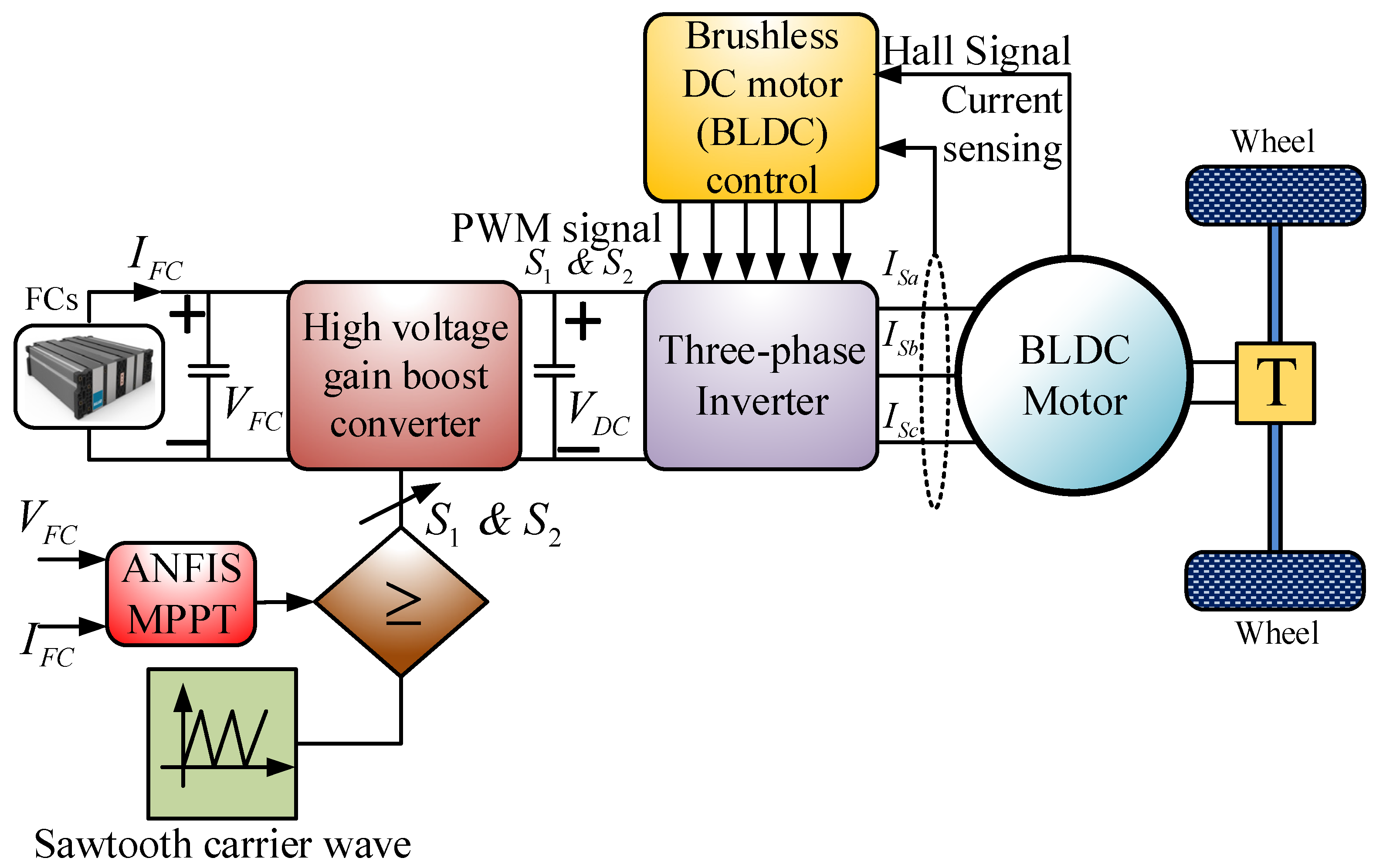
- Reddy, K.J.; Sudhakar, N. ANFIS-MPPT control algorithm for a PEMFC system used in electric vehicle applications. Int. J. Hydrogen Energy 2019, 44, 15355–15369. [Google Scholar] [CrossRef]
- Hussain, S.; Ali, M.U.; Park, G.; Nengroo, S.H.; Khan, M.A.; Kim, H. A real-time bi-adaptive controller-based energy hybrid electric vehicles. Energies 2019, 12, 4662. [Google Scholar] [CrossRef]
- Vidhya, S.D.; Balaji, M. Hybrid fuzzy PI controlled multi-input DC/DC converter for electric vehicle application. J. Control. Meas. Electron. Comput. Commun. 2020, 61, 79–91. [Google Scholar]
- Yilmaz, U.; Turksoy, O.; Teke, A. Intelligent control of high energy efficient two-stage battery charger topology for electric vehicles. Energy 2019, 186, 115825. [Google Scholar] [CrossRef]
- Sai Teja, T.; Yaseen, M.D.; Anilkumar, T. Bidirectional DC to DC converter with ANN controller for hybrid electric vehicle. Int. J. Innov. Technol. Explor. Eng. 2019, 8, 4446–4453. [Google Scholar]
- Wang, B.; Wang, C.; Hu, Q.; Ma, G.; Zhou, J. Adaptive sliding mode control with enhanced optimal reaching law for boost converter based hybrid power sources in electric vehicles. J. Power Electron. 2019, 19, 549–559. [Google Scholar]
- Wu, Y.; Huangfu, Y.; Ma, R.; Ravey, A.; Chrenko, D. A strong robust DC-DC converter of all-digital high-order sliding mode control for fuel cell power applications. J. Power Sour. 2019, 413, 222–232. [Google Scholar] [CrossRef]
- Drakunov, S.V.; Reyhanoglu, M.; Singh, B. Sliding mode control of DC-DC power converters. IFAC Proc. Vol. 2009, 42, 237–242. [Google Scholar] [CrossRef]
- Dai, P.; Cauet, S.; Coirault, P. Passivity-based control and Sliding Mode Control of hybrid DC power source applied to Hybrid Electric Vehicles. In Proceedings of the International Conference on Systems and Control, Algiers, Algeria, 29–31 October 2013; Institute of Electrical and Electronics Engineers Inc.: New York, NY, USA, 2013; pp. 691–696. [Google Scholar]
- Wang, J.; Xu, D.; Zhou, H.; Zhou, T. Adaptive fractional order sliding mode control for Boost converter in the Battery/Supercapacitor HESS. PLoS ONE 2018, 13, e0196501. [Google Scholar] [CrossRef] [PubMed]
- Liu, K.; Li, K.; Zhang, C. Constrained generalized predictive control of battery charging process based on a coupled thermoelectric model. J. Power Sources 2017, 347, 145–158. [Google Scholar] [CrossRef]
- Ouyang, Q.; Wang, Z.; Liu, K.; Xu, G.; Li, Y. Optimal Charging Control for Lithium-Ion Battery Packs: A Distributed Average Tracking Approach. IEEE Trans. Ind. Inf. 2020, 16, 3430–3438. [Google Scholar] [CrossRef]
- Kummara, V.G.R.; Zeb, K.; Muthusamy, A.; Krishna, T.N.V.; Prabhudeva Kumar, S.V.S.V.; Kim, D.H.; Kim, M.S.; Cho, H.G.; Kim, H.J. A comprehensive review of DC–DC converter topologies and modulation strategies with recent advances in solar photovoltaic systems. Electronics 2020, 9, 31. [Google Scholar] [CrossRef]
- Prabaharan, N.; Palanisamy, K. A comprehensive review on reduced switch multilevel inverter topologies, modulation techniques and applications. Renew. Sustain. Energy Rev. 2017, 76, 1248–1282. [Google Scholar] [CrossRef]
- Salehahari, S.; Babaei, E. A new hybrid multilevel inverter based on coupled-inductor and cascaded H-bridge. In Proceedings of the 2016 13th International Conference on Electrical Engineering/Electronics, Computer, Telecommunications and Information Technology, ECTI-CON 2016, Chiang Mai, Thailand, 28 June–1 July 2016; Institute of Electrical and Electronics Engineers Inc.: New York, NY, USA, 2016; pp. 1–6. [Google Scholar]
- Seeman, M.D.; Sanders, S.R. Analysis and optimization of switched-capacitor DC-DC converters. IEEE Trans. Power Electron. 2008, 23, 841–851. [Google Scholar] [CrossRef]
- Busquets-Monge, S.; Crebier, J.C.; Ragon, S.; Hertz, E.; Boroyevich, D.; Gürdal, Z.; Arpilliere, M.; Lindner, D.K. Design of a boost power factor correction converter using optimization techniques. IEEE Trans. Power Electron. 2004, 19, 1388–1396. [Google Scholar] [CrossRef]
- De Leon-Aldaco, S.E.; Calleja, H.; Aguayo Alquicira, J. Metaheuristic Optimization Methods Applied to Power Converters: A Review. IEEE Trans. Power Electron. 2015, 30, 6791–6803. [Google Scholar] [CrossRef]
- Liu, K.; Zou, C.; Li, K.; Wik, T. Charging pattern optimization for lithium-ion batteries with an electrothermal-aging model. IEEE Trans. Ind. Inf. 2018, 14, 5463–5474. [Google Scholar] [CrossRef]
- Liu, K.; Hu, X.; Yang, Z.; Xie, Y.; Feng, S. Lithium-ion battery charging management considering economic costs of electrical energy loss and battery degradation. Energy Convers. Manag. 2019, 195, 167–179. [Google Scholar] [CrossRef]


| DC-DC Converter | Current/Voltage Ripple | Switching Frequency | Complexity of Control Circuit | High Power Conversion | EMI Suppression | Cost | Voltage Gain | Active Components | Passive Components | |||
|---|---|---|---|---|---|---|---|---|---|---|---|---|
| D | SW | HFT | L | C | ||||||||
| CC | Simple | High | Simple | Appropriate | Reduced | Low | 2 | 2 | 0 | 2 | 2 | |
| SCBC | Moderate | High | Moderate | Appropriate | Needed | Medium | 4 | 4 | 0 | 1 | 3 | |
| CIBC | Moderate | High | Moderate | Appropriate | Needed | Low | 3 | 3 | 0 | 2 | 3 | |
| QZBC | Simple | High | Complex | Appropriate | Needed | Medium | 3 | 3 | 0 | 2 | 3 | |
| MDIBC | Complex | Low | Complex | Appropriate | Reduced | Low | 16 | 16 | 0 | 4 | 1 | |
| PPC | Simple | High | Complex | Appropriate | Reduced | Low | 4 | 4 | 1 | 1 | 1 | |
| FC | Simple | High | Moderate | Not appropriate | Needed | Low | 2 | 2 | 1 | 0 | 2 | |
| RC | Simple | High | Moderate | Appropriate | Reduced | Low | 8 | 8 | 1 | 2 | 3 | |
| ZVSC | Complex | Low | Complex | Appropriate | Reduced | Medium | 4 | 4 | 1 | 1 | 5 | |
| MPIC | Complex | Low | Complex | Appropriate | Needed | High | 12 | 12 | 1 | 2 | 1 | |
| Type | Ref. | DC-DC Converter | Objective | Outcomes | Benefits | Drawbacks |
|---|---|---|---|---|---|---|
| Non-isolated converter | [92] | CC | -To prevent high energy loss. | -Provides stable and ripple-free output. | -Peak-to-peak ripple current of inductors is smaller. -Continuous input and output currents. | -Difficult to stabilize. -Uncontrolled and undamped resonance. |
| [93] | SCBC | -To obtain high voltage gain and efficiency. | -Efficiency is greater than 90%. | -Cost-effective. -Compact design. -Current output limited. | -High ripple current. -Fails to maintain higher efficiency for a wide range of ratios of input to output voltages. | |
| [106] | CIBC | -To reduce output current and inductor current ripples. | -Increase in the efficiency by increasing coupling coefficient. | -Small size. -Low cost. -Reduced ripples. | -Limited scope for further improvement. -No consideration for voltage ripples. | |
| [112] | QZBC | -To obtain wide range of voltage gain, and an absolute common ground. | -Maximum and minimum efficiency are 96.44% and88.17%, respectively. | -Lower switch stress. -Smaller component ratings. -Buck/boost capability. | -Input current is discontinuous. -Capacitor has high voltage stress. | |
| [121] | MDBIC | -To reduce the number of passive components. -To decrease the ripples in input current and output voltage. -To obtain proper control and fast transient response. | -Obtains low EMI and low stress. -Halves current and voltage ripple in comparison to interleaved boost converter (IBC). -Halves inductor and capacitor size compared to IBC. | -Low current stress. -High efficiency. -Ideal for high-power conversion. -Simple control approach. -Reduced heat sink and component size. | -Complex circuit due to the high number of components. -Duty cycle is very sensitive under load variation. -Study under steady-state and transient conditions is complex. | |
| Isolated converter | [130] | PPC | -To change the voltage of DC power supply. | -Limits the starting power. -Achieves low current and voltage on the primary side. | -Better utilization of transistors and transformers. -Reduces EMI. -Less filtering required. | -Central tap transformer. -Two switches are not widely used in flux walking phenomena. |
| [139] | FC | -To enable support of a wide input voltage range. | -Attains lower leakage inductance to an acceptable limit. | -Primary is isolated from the output. -Can provide multiple output voltages. -Ability to regulate the multiple output voltages. | -Has ripple current. -Higher losses. -More output and input capacitance. -Has the right half pole in the compensation loop. | |
| [145] | RC | -To minimize magnetic components and passive filters. | -Obtains high step-up/down capability. -Achieves high efficiency. -Attains wide voltage gain range. | -Low cost. -High conversion ratio. -High efficiency. | -Expensive controller. -Complex integrated transformer. | |
| [151] | ZVSC | -To provide satisfactory power under wide range load variations. -To perform the soft-switching with acceptable efficiency. -To clamp the output diode bridge voltage. | -Achieves zero voltage switching under all load conditions. -Ensures a stable and reliable process under no-load condition through the symmetric auxiliary circuits. | -Low EMI. -Low switching loss. -Additional clamping circuit is not required. | -Large capacitor is needed. -High current ratings. -Poor fault-tolerant capability. | |
| [155] | MPIC | -To control duty cycle to optimize the system behavior. -To minimize the overall system losses. -To investigate the dynamic analysis and related control strategy. | -Achieves a fast dynamic response. -Independent control of power flow. -Achieves high efficiency through duty cycle control and phase-shift control. | -High voltage gain. -Low output voltage ripple current. -Galvanic isolation. | -Large number of components. -Complex analysis under steady-state and transient conditions. -High sensitivity corresponds to duty cycle under load changes. -Difficult to achieve proper synchronization. |
| Feature | Proportional Integral (PI) Control | Fuzzy Control | Artificial Neural Network (ANN) Control | Sliding Mode (SM) Control |
|---|---|---|---|---|
| Control operation | Linear | Artificial intelligence | Artificial intelligence | Non-linear |
| Control complexity | Medium | Less | High | High |
| Mathematical modeling | Required | Not required | Not required | Required |
| Sensitivity | High | Low | Low | Low |
| Dynamic response | Average | Excellent | Excellent | Good |
| overshoot | Large | Negligible | Negligible | Negligible |
| Control suitability | Lower order systems | All types of system | All types of system | All types of system |
| Capability to handle complexity | Difficult | Very easy | Easy | Easy |
| Ref. | Control Technique | Target | Contributions | Advantages | Disadvantages |
|---|---|---|---|---|---|
| [164] | PI control | -To control input voltage and output current. -To reduce the error between the reference current and the inner loop of the active current component. | -Manages to reduce the current component to zero. - Helps to balance the active power flow. - Ensures unity power factor operation.-Reduces the steady-state error. | -Easy execution. -Simple design. -Unstable operation due to inappropriate tuning. | -Needs precise mathematical modeling. -Inappropriate for highly non-linear, time-varying systems. -Poor transient response under a time-delayed system. |
| [167] | Fuzzy control | -To control peak current, voltage andaverage power demand. -To achieve high efficiency. -To interface between ESSs, generator and the voltage DC-link bus. | -Proper coordination between ESSs, including BSSs, SCs, FCs and load. - Confirms sufficient conditions for traction system operation. | -Robust, flexible, smooth and fast response. -Minimizes voltage and current ripple. -Improves dynamics and excellent transient response. -Can handle non-linear systems and work with imprecise inputs. | -Needs expert knowledge to design the controller. -Generation of fuzzy rules is a laborious task. -Needs frequent upgrades of fuzzy rules. |
| [173] | ANN Control | -To achieve high power factor, low harmonics of input current and high efficiency. -To obtain a higher battery life expectancy. | -Obtains peak efficiency, ripple voltage and total harmonic distortion (THD) of 96.2%, 0.5 V and below 5%, respectively. | -Accurate and robust. -Flexible controllability. -Improved transient response. -Satisfactory operation under varying loads. | -Suffers from computational complexity problems. -Not ideal for fast switching operations. -Needs expensive processor devices. |
| [179] | SM control | -To attain current tracking control. | -High robustness. -Minimizes 80% of the transient time during the startup condition. -Allows the ESSs to reach a steady-state condition promptly. | -Reliable and robust. -Excellent dynamic response. -Easy execution. -Improved stability. | -Switching frequency fluctuates under voltage and load variation. -Frequency variation affects the design process of input and output filters. -Selection of appropriate parameters is challenging due to the high control complexity. |
| Type | Converter | Authors | Modulation Techniques | Remarks |
|---|---|---|---|---|
| Non-isolated converter | CC | Pandey and Singh [91] | Pulse-width modulation | The authors proposed pulse-width modulation (PWM) control-based Cuk converter to achieve harmonic free input current in EVs. The outer loop is designed by the DC link control while the internal current control loop is formed using the input inductor current feedback. |
| SCBC | Zhang et al. [96] | Pulse-width modulation | The authors employed PWM schemes in SCBC converters for EVs to generate the gate signals in the step-up mode and step-down mode. | |
| CIBC | Salehahari and Babaei [184] | High-frequency pulse-width modulation | The authors used the high-frequency PWM method in a CIBC to obtain the effective switching frequency as well as produce the desired output voltage and reduce switching stresses. | |
| QZBC | Zhang et al. [112] | Pulse-width modulation | The authors designed the QZBC with PWM generator for EVs to produce three gate signals in the step-up mode and step-down mode. | |
| MDIBC | Hegazy et al. [121] | Pulse-width modulation | The authors suggested closed-loop control to develop an MDIBC based on PWM. Here, the authors used TMS320F2808 DSP-based real-time digital control synchronized with PWM to execute the dual-loop current control. | |
| Isolated converter | PPC | Hendra et al. [130] | Pulse-width modulation | The authors proposed a microcontroller-based control algorithm to generate a PWM duty cycle for an insulated-gate bipolar transistor (IGBT) using the date driver. |
| FC | Shen et al. [136] | Fixed frequency pulse-width modulation | The authors employed fixed frequency pulse-width modulation (FFPWM) to assess the electromagnetic interference (EMI) performance of the FC in EVs using the improved numerical model. | |
| RC | Moradisizkoohi et al. [143] | Quasi-resonant pulse-width modulation | The authors suggested quasi-resonant PWM (QRPWM) where the switching frequency is higher than the resonant frequency. The proposed QRPWM showed better performance with regard to lower turn-off loss. | |
| ZVSC | Pahlevaninezhad et al. [151] | Enhanced pulse-width modulation | The authors developed TMX320F28335 eZdSP with six EPWM modules not only to generate a high-resolution PWM signal and high degree of flexibility but also to limit instability. | |
| MPIC | Zhao et al. [155] | Modified pulse-width modulation | The authors utilized controllers and a decoupling network and three duty cycle lookup tables along with 100 kHz PWM patterns to adjust the two-phase shift angle lookup tables. |
| Algorithm | Ref. | Objective Function | Topology | Considered Factors | Outcomes |
|---|---|---|---|---|---|
| Genetic algorithm (GA) | [43] | -Maximizes the system efficiency. | -Bidirectional dual active bridge (DAB) converter. | -Leakage inductance, peak flux density, voltage conversion ratio and switching frequency. | -Eliminates the need for external inductors. |
| Non-dominated Sorting Genetic Algorithm II (NSGA-II) | [83] | -Minimizes the losses in the converter. | -Multi-objective, DC-DC multiport converters. | -Voltage and ripple current. | -Reduces the size, development time and input current ripple. |
| Particle swarm optimization (PSO) | [84] | -Switching angle optimization. | -KY boost converter. | -Voltage. | -Ripple current is reduced. |
| PSO | [85] | -Optimization of energy consumption. | -One-way DC-DC converter. | -Fuzzy membership functions are optimized. | -Reduces the influence of fuzzy control strategy. |
Publisher’s Note: MDPI stays neutral with regard to jurisdictional claims in published maps and institutional affiliations. |
© 2021 by the authors. Licensee MDPI, Basel, Switzerland. This article is an open access article distributed under the terms and conditions of the Creative Commons Attribution (CC BY) license (http://creativecommons.org/licenses/by/4.0/).
Share and Cite
Lipu, M.S.H.; Faisal, M.; Ansari, S.; Hannan, M.A.; Karim, T.F.; Ayob, A.; Hussain, A.; Miah, M.S.; Saad, M.H.M. Review of Electric Vehicle Converter Configurations, Control Schemes and Optimizations: Challenges and Suggestions. Electronics 2021, 10, 477. https://doi.org/10.3390/electronics10040477
Lipu MSH, Faisal M, Ansari S, Hannan MA, Karim TF, Ayob A, Hussain A, Miah MS, Saad MHM. Review of Electric Vehicle Converter Configurations, Control Schemes and Optimizations: Challenges and Suggestions. Electronics. 2021; 10(4):477. https://doi.org/10.3390/electronics10040477
Chicago/Turabian StyleLipu, Molla S. Hossain, Mohammad Faisal, Shaheer Ansari, Mahammad A. Hannan, Tahia F. Karim, Afida Ayob, Aini Hussain, Md. Sazal Miah, and Mohamad Hanif Md Saad. 2021. "Review of Electric Vehicle Converter Configurations, Control Schemes and Optimizations: Challenges and Suggestions" Electronics 10, no. 4: 477. https://doi.org/10.3390/electronics10040477
APA StyleLipu, M. S. H., Faisal, M., Ansari, S., Hannan, M. A., Karim, T. F., Ayob, A., Hussain, A., Miah, M. S., & Saad, M. H. M. (2021). Review of Electric Vehicle Converter Configurations, Control Schemes and Optimizations: Challenges and Suggestions. Electronics, 10(4), 477. https://doi.org/10.3390/electronics10040477