Article

Depolarizing Chipless Tags with Polarization Insensitive Capabilities

Dipartimento di Ingegneria dell’Informazione, Università di Pisa, 56122 Pisa, Italy
*
Author to whom correspondence should be addressed.
Electronics 2021, 10(4), 478; https://doi.org/10.3390/electronics10040478
Submission received: 1 January 2021 / Revised: 23 January 2021 / Accepted: 4 February 2021 / Published: 17 February 2021
(This article belongs to the Section Microwave and Wireless Communications)

Abstract

:
A novel depolarizing chipless tag configuration with high angular insensitivity is presented. The basic tag comprises two dipole resonators arranged with a relative rotation of 45°. The proposed configuration improves the depolarization properties performance of a single dipole over the ground plane which provides a peak with perfect polarization conversion only if the electric field impinges at 45° with respect to the dipole resonator. The second dipole arranged at 45° compensates the cross-polar reduction which is observed when the electric field is not correctly polarized. Indeed, when the field is tilted by 90° with respect to the first dipole, it forms an angle of 45° with the second one. The proposed configuration is also analyzed for providing multiple frequency peaks. A tag with 4 angular independent frequency peaks laying between 2 GHz and 5.5 GHz is designed. Angular frequency maps are used to illustrate the peculiar frequency shifts achieved when the electric fields rotate in the plane of the dipole. Finally, a prototype of the polarization insensitive tags is fabricated and measured to confirm the simulated results.

1. Introduction

The manipulation of the electric field polarization plays an important role in the design of several devices [1] and it has also been exploited for encoding purposes within the framework of chipless Radio Frequency Identification (RFID) tags. In a chipless RFID system the reader probes with an electromagnetic wave the tag which reflects back to the reader a fraction of the impinging power. The amount of the scattered power obviously depends on the geometric area of the tag that contributes to the overall Radar Cross Section (RCS). Moreover, in the case of a chip-less RFID tag, there is no Integrated Circuit (IC) or active circuit that can modulate the retransmitted signal therefore the reflection that the interrogating signal undergoes is essentially operated by the finite tag reflection coefficient profile. Several solutions have been proposed to tailor the copolar frequency response of a chipless tag in order to store information [2,3,4,5,6,7,8,9]. However, since the beginning of this new paradigm for encoding information, it has been apparent that the transmitted signal suffers from different interferences related to the reading system or the environment clutter and efforts have been also made to rigorously analyze this problem and assess the expected performance of this kind of systems [10]. It is also worthwhile to notice that there are also pioneering efforts toward the circumvention of this problem by using three dimensional tags [11,12,13,14] that rely on near field reader or almost omnidirectional scattered field. The increase of the chipless RFID area in order to exploit a greater RCS could overcome some of the limitations but the drawback of a cumbersome tag makes this option not viable. Moreover, even accepting this inconvenience, the presence of metallic objects close to the tag makes this solution not efficient since the electromagnetic echo of these surrounding scatterers completely overshadows the copolar response of the chipless tag. A significant improvement is obtained when the electric field reflected by the chipless RFID tag is orthogonal to the one caused by the untagged objects. Examples of this approach rely on the use of tags able to reflect a cross polar linear electric field component or an opposite-handedness circular one [15,16,17,18,19]. However, previous attempts of chipless RFID tags that generate a reflected field orthogonal to the incidence one for encoding purposes have proved to be sensitive to the relative orientation of the impinging electric field with respect to the tag [20] or to provide a low number of bits [21,22,23]. This paper addresses this issue by employing a novel tag configuration initially proposed in [21] and more recently in [22]. The resonator topology is motivated by using simulations of the infinite periodic tag configuration and trough an equivalent circuit approach. A multi-bit design able to provide a significant cross polar reflected electric field on multiple resonances regardless of the tag orientation is proposed. The paper is organized as follows. Section 2 reports the problem statement is terms of reflection coefficients and the condition for achieving ta perfect polarization rotation is highlighted. In Section 3, a simple design of a frequency selective polarization rotator is presented by showing its limitations in terms of azimuth interrogation angle. Section 4 presents a more elaborated unit cell topology for the chipless tag based on periodic surfaces which comprises a couple of dipoles specifically inclined to intercept the impinging electric and convert it into cross-polarized one independent of the azimuth incidence of the probing ElectroMagnetic (EM) wave [20,21]. The case of multiple resonant structure is also addressed. In Section 5, experimental results obtained on a two bits structure which confirms the validity of the proposed approach are presented. Finally, the issue of further increasing the number of resonances is addressed in Section 6 where a disordered dipole arrangement is proposed to reduce the mutual coupling level between the resonators.

2. Formulation

Let us consider a linearly polarized plane wave propagating in air along +z direction generated by an interrogating antenna. The incident field Ei can be written as:
E _ i = E 0   i _ x + E 0   i _ y
where ix and iy are the unit vectors along x-axis and y-axis, respectively, and E0 represents the magnitude of each component. The reflected electric field Eref can be expressed as:
E _ s = E x s i _ x + E y s i _ y = ( Γ x x E 0 + Γ x y E 0 )   i _ x + ( Γ y x E 0 + Γ y y E 0 )   i _ y
where Γxx and Γyy are the copolar reflection coefficients whereas Γxy and Γyx are the cross-polar ones. In case the interface is between air and a perfect electric conducting (PEC) surface, Γxx = Γyy = −1 and Γxy = Γxy = 0 and the polarization of the wave is unchanged. On the contrary, if the unit cell shape is polarization sensitive, in such a way that phase degree displacement of 180° is achieved between the x and y component of the reflected field (Γxx =1, Γyy = −1 and Γxy = Γxy = 0), a perfect polarization conversion can be accomplished.

3. Polarization Sensitive Chipless Tag

The above-mentioned condition can be achieved with a dipole unit cell over a ground plane. By exciting the unit cell with a linearly polarized incident field along the ϕ plane:
E _ i = E 0 cos ( ϕ i )   i _ x + E 0 sin ( ϕ i )   i _ y
This polarization converting condition is perfectly met for a dipole unit cell only if the impinging electric field is oriented along ϕi = 45° since in this case the unit cell is excited with an identical field both along x and y direction:
E _ i ( ϕ i = 45 ° ) = 1 2 E 0   i _ x + 1 2 E 0   i _ y
On the contrary, if the unit cell is more excited along one of the two principal planes, the perfect polarization conversion is not achieved as the x and y components of the electric field are unbalanced.
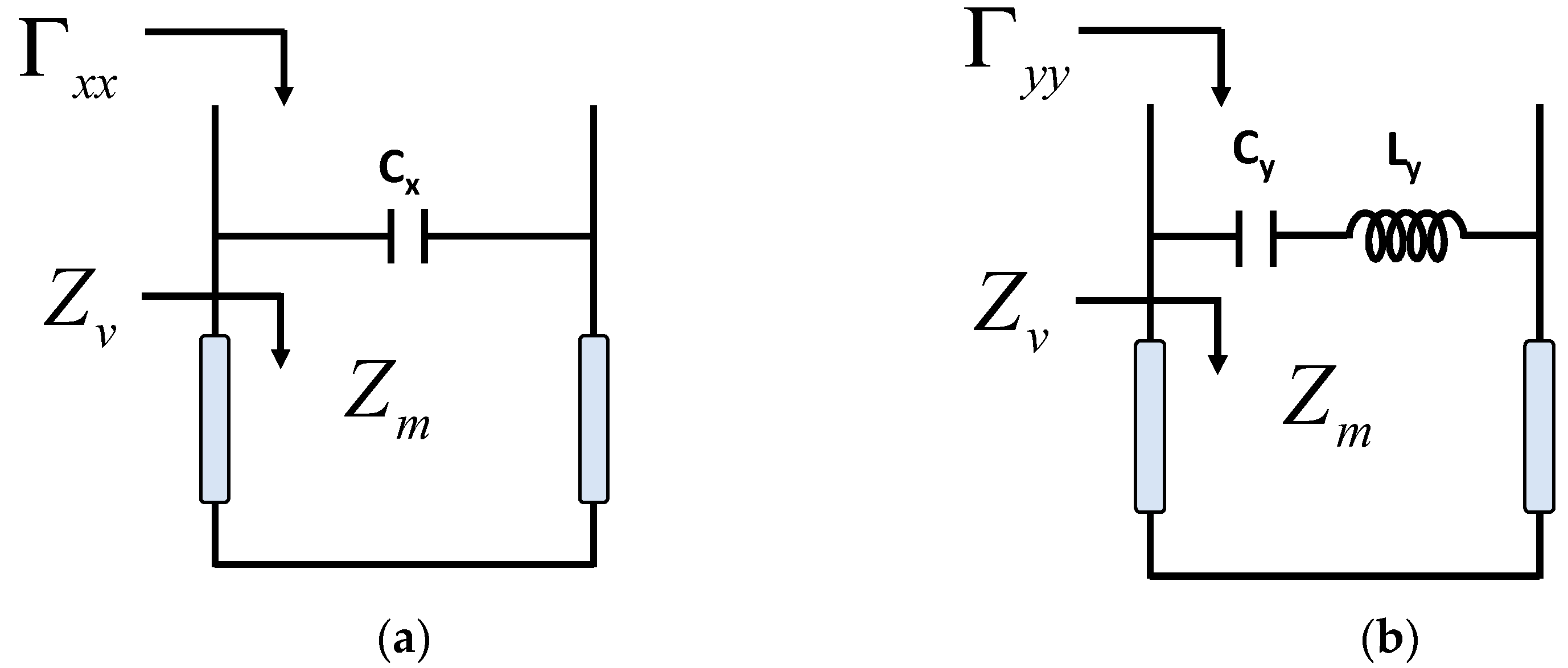
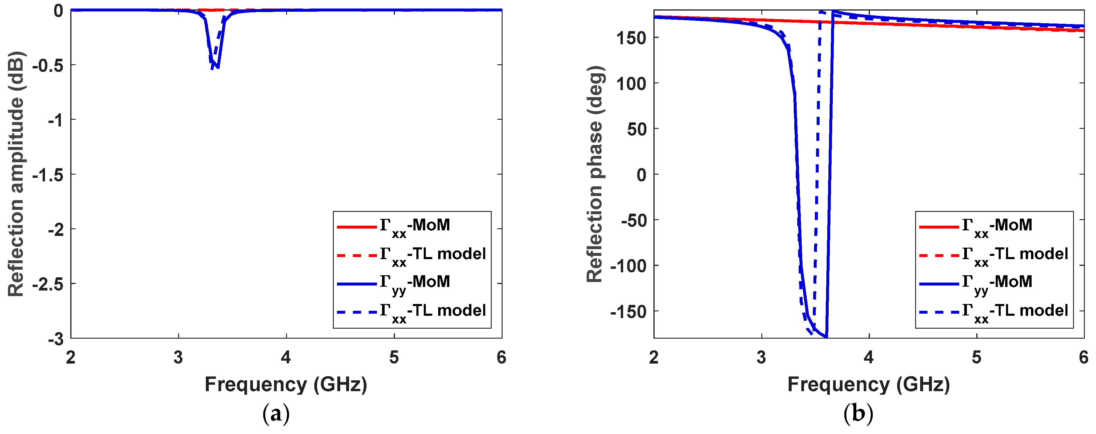
This behavior can be explained considering a linear polarized EM wave impinging on the Frequency Selective Surface (FSS) with an azimuthal angle equal to 45°. The electric field can be decomposed in the x and y components as shown in Figure 1a. In order to obtain a perfect polarization conversion, the reflected field needs to be oriented as shown in Figure 1b and the optimal conditions (Γxx = 1, Γyy = −1 and Γxy = Γxy = 0) need to be met. To have a better insight in the working principle of the device, an equivalent circuit model can be used. The model can be applied both for the x and y directions. For a field polarized towards x-direction, the dipole is orthogonal to the E-field and the periodic surface behaves as a capacitance. The circuit model for the x-directed and y-directed electric field are shown in Figure 2. On the contrary, a field directed towards y-direction fully excites the dipole resonator and the periodic surface can be schematized through a series LC circuit. The comparison between the impedance of the periodic surface with a periodicity of 10 mm extracted from Method of Moments (MoM) simulations and by using the lumped element schematization [24] is shown in Figure 3. The grounded substrate is schematized through a short transmission line closed on a short circuit. The reflection coefficient of the Artificial Impedance Surface (AIS) for x and y direction is shown in Figure 4. The phase difference of the x and y components of the reflected field is equal to 180° at the resonance frequency of the AIS. The periodic method of moments (MoM) [25] analysis considers the response of a unit cell of a periodic surface. This analysis is fast, and it is useful, at least in an initial stage, for assessing the performance of a specific element geometry.
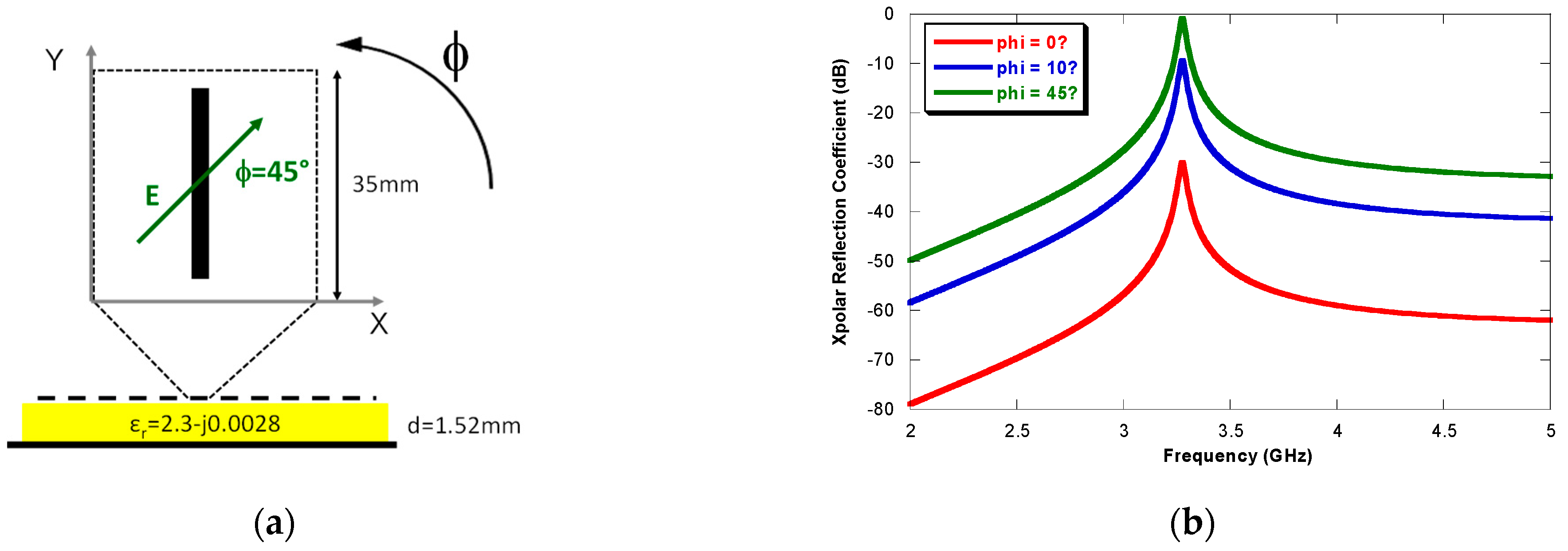
The dipole is an optimal linear polarization converter when the azimuthal angle of the impinging wave is 45°. This behavior of the dipole is shown in Figure 5b, in which the amplitude of the cross polar reflection coefficient simulated for three different azimuthal angles: ϕ = 0°, ϕ = 10°, ϕ = 45° is shown. The unit cell and the simulated stack-up is shown in Figure 5a. As evident from Figure 5b the optimum angle is ϕ = 45°. In fact, in this case, the dipole exhibits the maximum level of the cross polar reflection coefficient (0 dB). When the electric fields impinge with an azimuthal angle ϕ that is different from 45°, the AIS is not able to convert the polarization of the EM wave.
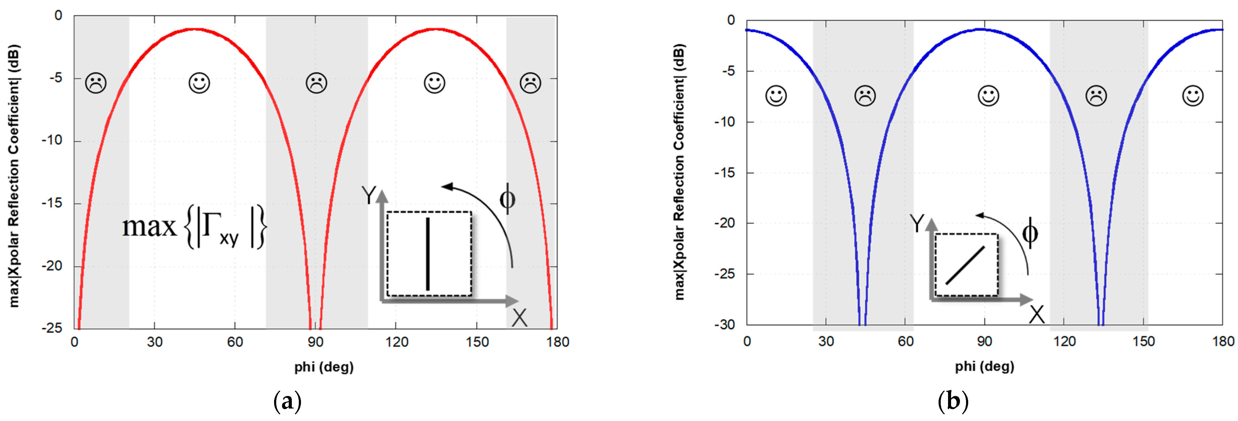
The angle ϕ = 45° is the only case in which the polarization conversion conditions are met. The selectivity of the peak can be increased by reducing the thickness of the substrate, but this may lead to a lower polarization conversion at the resonance frequency because of enhanced absorption loss of the substrate. In order to evaluate the behavior of the dipole with respect to the variation of the azimuth angle it is possible perform the simulation of the FSS for different values of ϕ ranging from 0° to 360°, thus obtaining numerous curves like the one reported in Figure 5b. Subsequently, it is possible to plot all the maximum values collected from each curve as a function of the ϕ angle thus obtaining the graph reported in Figure 6a. It is evident that there are some angular sectors in which the dipoles do not polarize the EM wave. In these angular sectors, that are indicated with the grey color in Figure 6a, the amplitude of the cross polar reflection coefficient is below −5 dB. It is interesting to observe the behavior of the dipole when it is tilted by 45° over the ϕ direction. In this case, the angular sector in which the performance of the polarizer are not acceptable are shifted of 45° over the ϕ direction with respect to the vertical dipole. In light of these results, in order to obtain a polarization converter which is robust to the rotation over the angle ϕ, it is natural to put together the two dipoles in the same unit cell.

4. Polarization Insensitive Chipless Tag

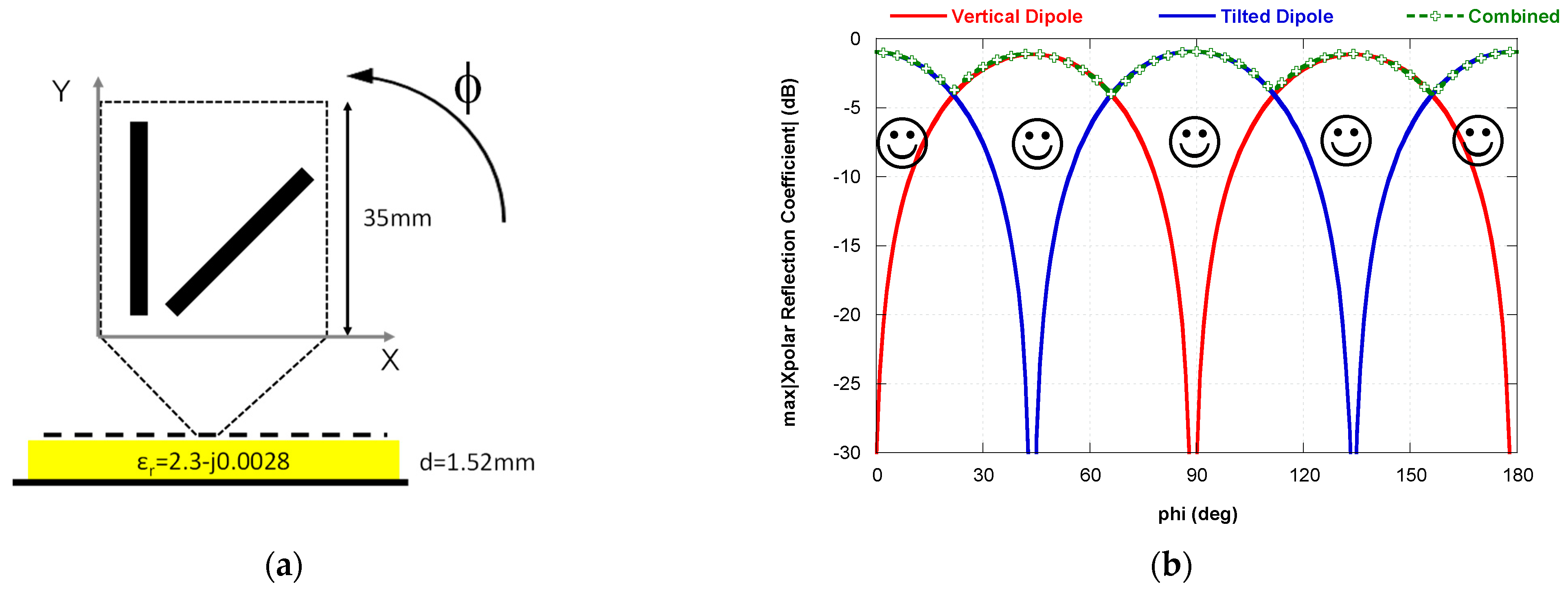
In Figure 7a the stack-up and unit cell obtained by the combination of the vertical ad 45°-tilted dipole is shown. For this unit cell it is possible to perform the simulation of the FSS for different values of the ϕ angle in order to obtain the graph presented in Figure 7b. The combination of the two resonant dipoles provides a polarization converter which exhibits good polarization capabilities with respect to the variation of the azimuthal angle. In fact, the maximum of the amplitude of the cross polar reflection coefficient reported in Figure 7b is higher than −5dB for every azimuthal angle. The 45°-tilted provides a high value of the cross polar reflection coefficient when the vertical dipole is not able to polarize the EM wave and vice versa. This complementary behavior of the two dipoles is clearly visible in Figure 8a where the Amplitude of the cross polar reflection coefficient simulated for three different azimuthal angles: ϕ = 0°, ϕ = 10°, ϕ = 45° for the unit cell with the vertical and 45°-tilted dipole is shown. Figure 8a shows that the vertical dipoles convert the polarization of electric field for ϕ = 45° whereas the 45°-tilted dipole is not working. On the contrary, when ϕ = 10° or ϕ = 0° the polarization conversion is due to the 45°-tilted dipole whereas the vertical dipole is not working. A pictorial representation of the different sectorial angles in which alternatively one of the two dipoles works is reported in Figure 8b.
It can be noted from Figure 8a that the robustness of the unit cell with respect to the rotation angle ϕ is obtained at the cost of a wider operative bandwidth of the polarization converter. In fact, despite the vertical and the 45°-tilted dipole having the same length they resonate at two different frequency because of the mutual coupling effect between the two resonant elements. Moreover, if the two dipoles are tuned in order to resonate at the same frequency, the polarization conversion capability of the unit cell results degraded. Consequently, this polarization converter can be employed as a chipless RFID tag if the operative bandwidth of the reader is compatible with the operative bandwidth of the tag.
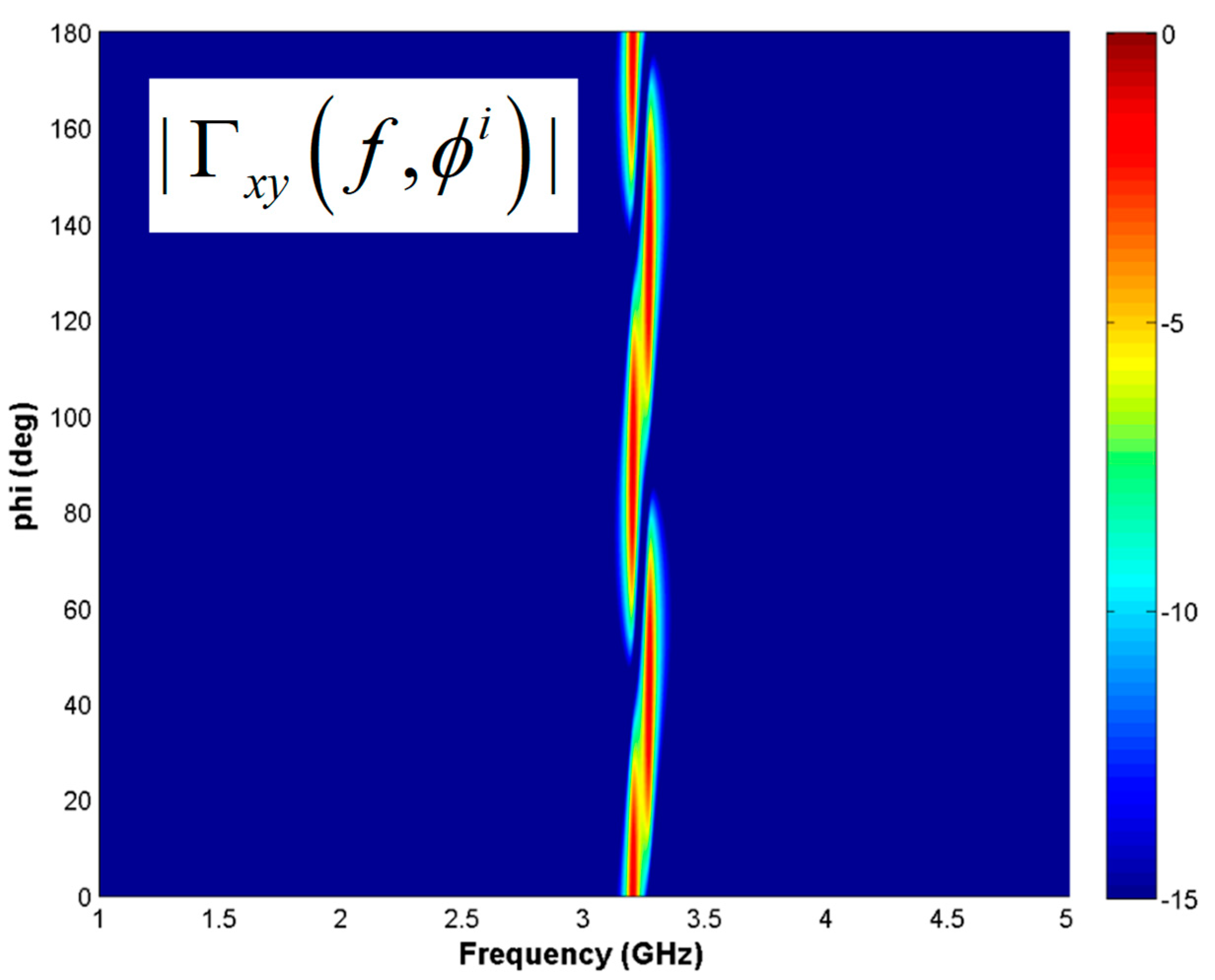
The robustness of the combined unit cell is it evident in the bidimensional false color map in which the amplitude of the cross polar reflection coefficient as a function of the frequency and rotation angle ϕ is shown in Figure 9.
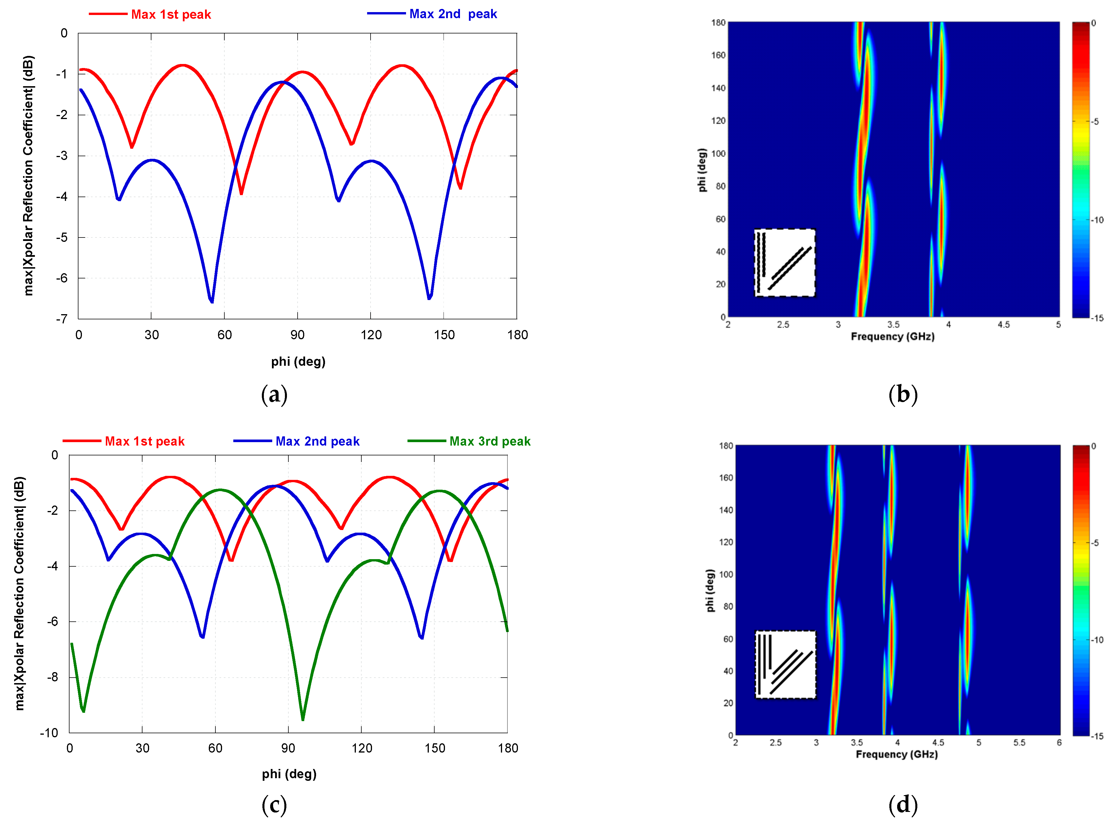
The map has been obtained by extracting the behavior of the reflection coefficient of the AIS surface for all azimuth angles with the analytical post-processing procedure described in the Appendix A. The procedure allows to extract the azimuth angle behaviour of the unit cell from a single full wave simulation with a fixed azimuth angle. From the graph it is evident the alternation in the operation of the two dipoles. On the basis of the unit cell topology shown in Figure 7a it is possible to obtain a multiband polarization converter by adding pairs of dipoles in the unit cell. The maximum of the amplitude of the cross polar reflection coefficient as a function of the azimuthal angle for the dual-band and tri-band polarization converter are respectively shown in Figure 10a,c. In Figure 10b,d the bidimensional false color map of the amplitude of the cross polar reflection coefficient as a function of the frequency and rotation angle ϕ for the dual-band and tri-band polarization converter is reported.
As is evident from the figures, the introduction of additional pairs of dipoles slightly reduces the performance of the polarization converter. Nevertheless, the proposed polarizer is considerably more robust with respect to the variation of the rotation angle in comparison to the vertical dipole. It is worth highlighting that the performance provided by the proposed polarization converter are particularly desirable in a real chipless RFID scenario in which the position of the tag is unknown.

5. Experimental Results

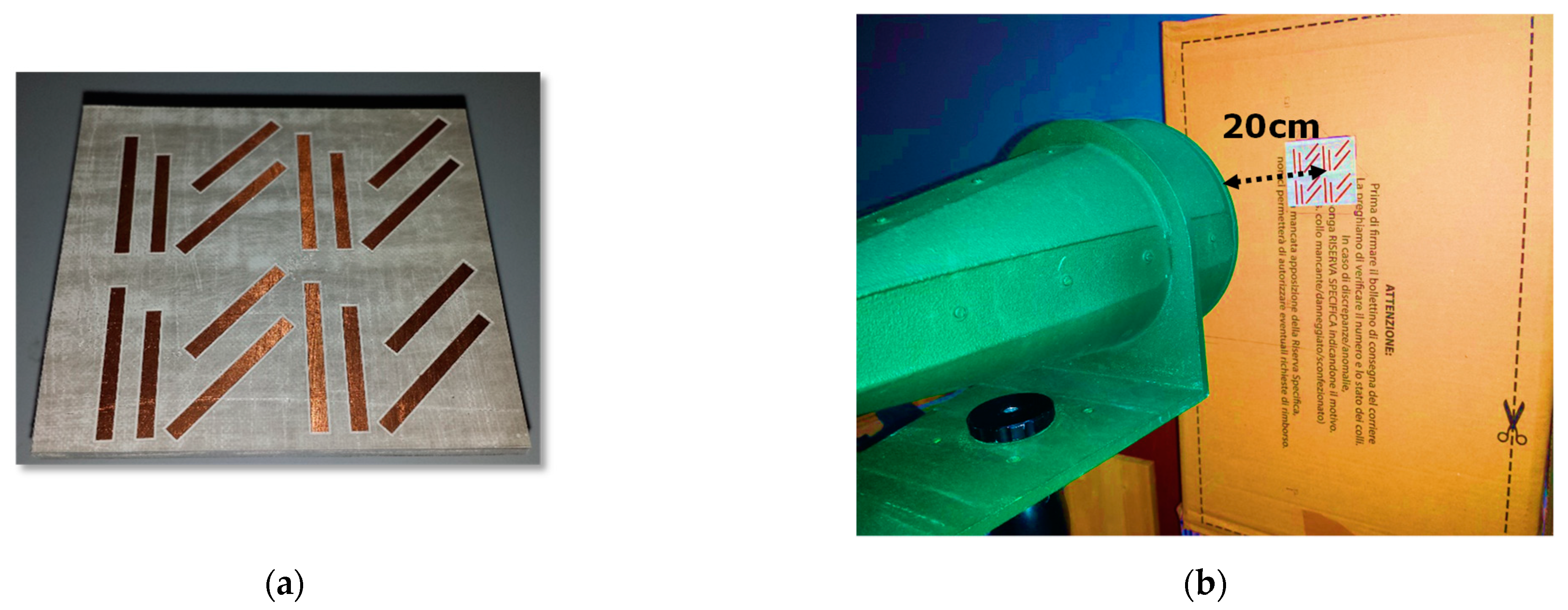
The prototype of a dual-band polarization converter composed by a 2 × 2 periodic surface has been fabricated. The resonant dipoles are placed on a grounded substrate of a grounded low loss dielectric (CER-10) with a thickness of 3.19 mm. The periodicity of the unit cell is 3 cm, thus obtaining a periodic surface with an overall area of 6.5 cm × 6.5 cm. The prototype has been fabricated with a numerical control milling machine. Consequently, the stack-up and the physical dimension of the polarizer have been determined by the availability of the dielectric materials of the laboratory.
The fabricated prototype is shown in Figure 11a. The measurements have been performed with a dual-polarized horn (Flann DP240) placed in front of the tag at a distance R = 25 cm as shown in Figure 11b. A prototype without the 45° tilted dipoles has been fabricated and compared to the polarization converter based on the combined cell.
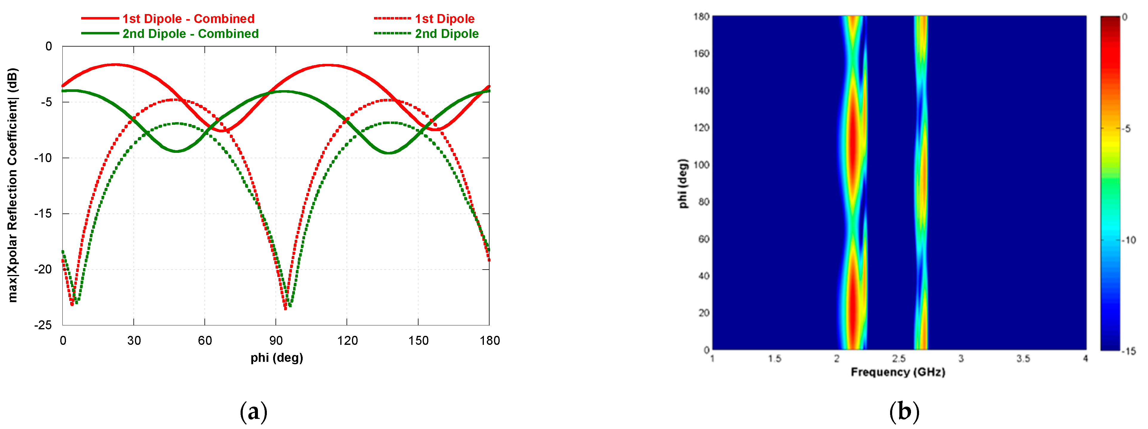
In Figure 12a the maximum of the amplitude of the measured crosspolar reflection coefficient as a function of the azimuthal angle for the dual-band polarization converter (continuous lines) and for the polarization converter without the 45°-tilted dipoles (dotted lines). It is evident that the 45°-tilted dipoles allows to obtain a polarization converted robust over the 360° of the rotation angles ϕ. In Figure 12b the bidimensional false color map of the amplitude of the measured cross polar reflection coefficient as a function of the frequency and rotation angle ϕ for the dual-band polarization converter is shown.

6. Increasing Number of Bits

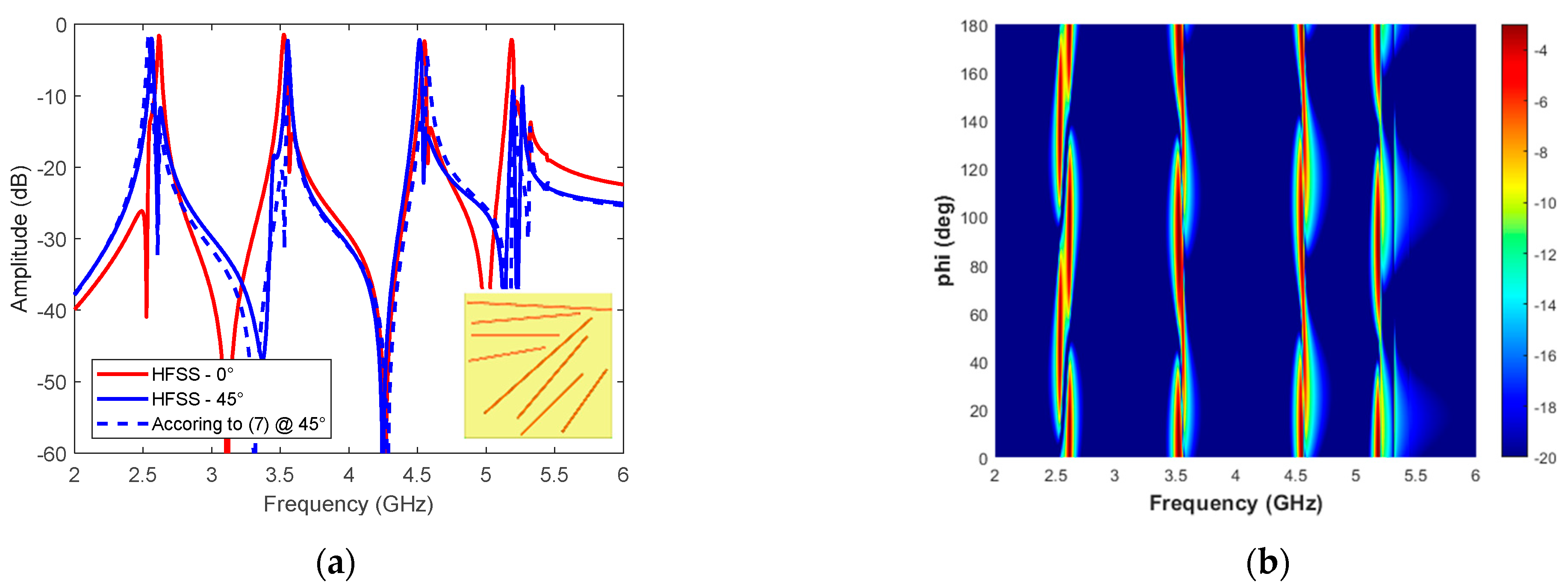
In order to further increasing the number of bits, the number of dipoles need to be increased inside the unit cell. Unfortunately, the increase of the number of dipoles with very close resonance frequencies, leads to a distortion of the frequency response of the tag due to mutual coupling effects among the dipoles. In order to circumvent this issue, we propose to accommodate the dipoles in a disordered way inside the unit cell. This allows to drastically reduce the coupling between closely placed metallic resonators. Clearly this approach is less automatic and need a more careful design of the unit cell geometry. An optimization loop for the optimal disposition of the dipoles and to trim their lengths would be needed to further increase the number of bits. An example with four bits is provided in Figure 13 where the cross-polar level is reported for different angles ϕ and the bidimensional false color map is reported to highlight the stability of the four resonances. The geometry of the unit cells is shown in the inset of Figure 13a.

7. Conclusions

A novel depolarizing chipless tag configuration has been introduced and thoroughly analyzed. The presented structure can encode in its cross-polar response a multi-bit sequence thanks to a proper design and arrangements of couples of dipoles printed on a grounded dielectric slab. Detailed circuit models have been provided and discussed for an in-depth analysis of the mechanism that guarantees the polarization conversion. The final structure achieves a remarkable stability of the frequency response regardless of its rotational angular orientation with respect to the probing radiation. Assessments of the expected performance have been done on a manufactured prototype and confirm the reliability and robustness of this innovative chipless RFID tag design.

Author Contributions

Conceptualization, M.B., F.C., S.G.; methodology, M.B., F.C.; software, M.B., F.C.; validation, M.B., F.C., S.G.; writing—original draft preparation, F.C., M.B., S.G.; supervision, G.M.; project administration, F.C., S.G., G.M.; funding acquisition, F.C., S.G., G.M. All authors have read and agreed to the published version of the manuscript.

Funding

Work partially supported by the Italian Ministry of Education and Research (MIUR) in the framework of the CrossLab project (Departments of Excellence) and the PRIN2017 GREEN TAGS "Chipless radio frequency identification (RFID) for GREEN TAGging and Sensing" (approved: 01/04/2019) 2017NT5W7Z.

Informed Consent Statement

Not applicable.

Conflicts of Interest

The authors declare no conflict of interest.

Appendix A. Field Reconstruction on a Generic Azimuth Plane
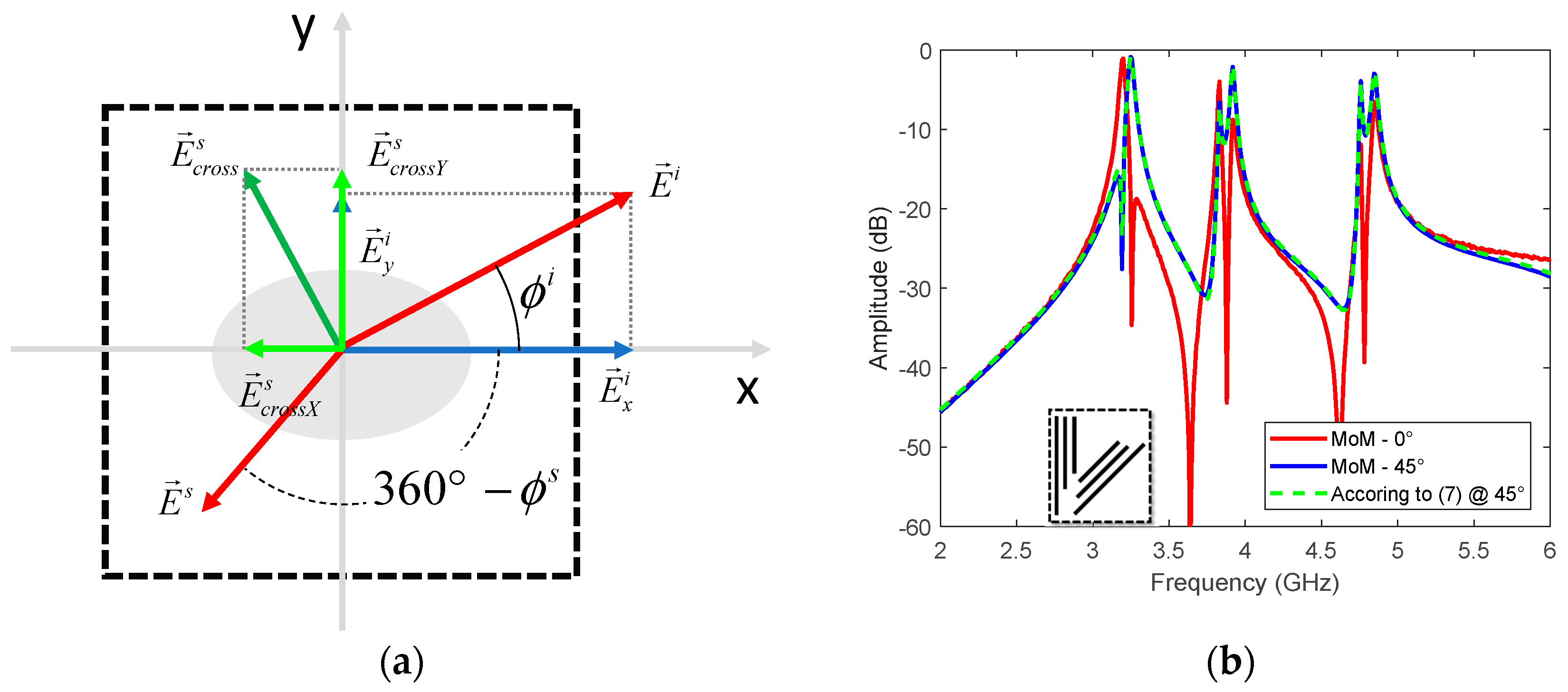
In this section a procedure to compute the scattered field from a periodic surface for a generic azimuth angle without the need to repeat the full-wave simulation is shown. This procedure allowed to generate the false color plots as a function of the frequency and the azimuth angle by just simulating the unit cell at ϕ i = 0° with two modes. Let us consider the incident electric field at a generic azimuth angle as shown in Figure A1a. The analytical computation of the reflection coefficient at a generic azimuth angle can be formulated as follows. The orthogonal direction is therefore individuated by the following unit vector given by the impinging electric field direction multiplied by the 90° rotation matrix:
E c r o s s s = R ( φ r o t = 90 ° ) E i
where R is the rotation matrix computed for a rotation of 90°:
R ( φ r o t = 90 ° ) = ( cos ( φ r o t ) - sin ( φ r o t ) sin ( φ r o t ) cos ( φ r o t ) ) = ( 0 −1 1 0 )
and the unit vector E ^ i = E i E i with E i = E x i _ x + E y i _ y = E 0 cos ( ϕ i ) + E 0 sin ( ϕ i ) . For simplicity E0 = 1.
The scattered field computed in the direction perpendicular to the impinging one is given by the scattered field projected in the direction individuated by relation (4) as:
E c r o s s s = E s ·   ( R ( φ r o t = 90 ° ) E i E i )
By replacing (4) and (A1) in (A2) we get:
E c r o s s s = ( E x s E y s ) ( 0 1 1 0 ) ( E x i E i E y i E i ) = ( R x x R x y R y x R y y ) ( E x i E y i ) ( E y i E i E x i E i ) =   ( R x x E x i + R x y E y i R y x E x i + R y y E y i ) ( E y i E i E x i E i ) = ( R x x E x i + R x y E y i ) ( E y i E i ) + ( R y x E x i + R x y E y i ) ( E x i E i ) = ( R x x E x i + R x y E y i ) ( sin ( ϕ i ) ) + ( R y x E x i + R x y E y i ) ( cos ( ϕ i ) )
To verify the proposed procedure, the reflection coefficient of a unit cell with four dipoles has been simulated by using a periodic MoM code (PMoM) [25] both for ϕ i = 0° and ϕ i = 45°. The behavior of the reflected field at ϕ i = 45° has been also computed by using relation (A3) starting from the data of the simulation with ϕ i = 0°. As is evident, the results match perfectly.
Figure A1. (a) Representation of the incident field and the scattered field on a generic unit cell shape. (b) Frequency behavior of a four dipoles unit cell shown in the inset over a 1.52 mm thick grounded Teflon substrate. The frequency behavior simulated at ϕ i = 0° and ϕ i = 45° is compared with the result obtained according to relation (A3) by using the data simulated at ϕ i = 0° without repeating the EM simulation.
Electronics 10 00478 g0a1

References

  1. Costa, F.; Borgese, M. Metamaterials, Metasurfaces and Applications. In Compendium on Electromagnetic Analysis; World Scientific: Singapore, 2020; pp. 89–169. ISBN 978-981-327-029-9. [Google Scholar] [CrossRef]
  2. Costa, F.; Genovesi, S.; Monorchio, A. A Chipless RFID Based on Multiresonant High-Impedance Surfaces. IEEE Trans. Microw. Theory Tech. 2013, 61, 146–153. [Google Scholar] [CrossRef]
  3. Tedjini, S.; Karmakar, N.; Perret, E.; Vena, A.; Koswatta, R.; E-Azim, R. Hold the Chips: Chipless Technology, an Alternative Technique for RFID. IEEE Microw. Mag. 2013, 14, 56–65. [Google Scholar] [CrossRef]
  4. Costa, F.; Genovesi, S.; Monorchio, A.; Manara, G. A Robust Differential-Amplitude Codification for Chipless RFID. IEEE Microw. Wirel. Components Lett. 2015, 25, 832–834. [Google Scholar] [CrossRef]
  5. Genovesi, S.; Costa, F.; Monorchio, A.; Manara, G. Chipless RFID Tag Exploiting Multifrequency Delta-Phase Quantization Encoding. IEEE Antennas Wirel. Propag. Lett. 2016, 15, 738–741. [Google Scholar] [CrossRef]
  6. Balbin, I.; Karmakar, N.C. Phase-Encoded Chipless RFID Transponder for Large-Scale Low-Cost Applications. IEEE Microw. Wirel. Components Lett. 2009, 19, 509–511. [Google Scholar] [CrossRef]
  7. Vena, A.; Perret, E.; Tedjini, S. Chipless RFID Tag Using Hybrid Coding Technique. IEEE Trans. Microw. Theory Tech. 2011, 59, 3356–3364. [Google Scholar] [CrossRef]
  8. Brinker, K.R.; Zoughi, R. Corner Reflector Based Misalignment-Tolerant Chipless RFID Tag Design Methodology. IEEE J. Radio Freq. Identif. 2020, 1. [Google Scholar] [CrossRef]
  9. Costa, F.; Borgese, M.; Gentile, A.; Buoncristiani, L.; Genovesi, S.; Dicandia, F.A.; Bianchi, D.; Monorchio, A.; Manara, G. Robust Reading Approach for Moving Chipless RFID Tags by Using ISAR Processing. IEEE Trans. Microw. Theory Tech. 2017, 66, 2442–2451. [Google Scholar] [CrossRef]
  10. Borgese, M.; Genovesi, S.; Manara, G.; Costa, F. Radar Cross Section of Chipless RFID tags and BER Performance. IEEE Trans. Antennas Propag. 2020, 1. [Google Scholar] [CrossRef]
  11. Ramirez, R.A.; Rojas-Nastrucci, E.A.; Weller, T.M. UHF RFID Tags for On-/Off-Metal Applications Fabricated Using Additive Manufacturing. IEEE Antennas Wirel. Propag. Lett. 2017, 16, 1635–1638. [Google Scholar] [CrossRef]
  12. Terranova, S.; Costa, F.; Manara, G.; Genovesi, S. Three-Dimensional Chipless RFID Tags: Fabrication through Additive Manufacturing. Sensors 2020, 20, 4740. [Google Scholar] [CrossRef]
  13. Li, Q.; Chen, J.; Zhao, L. Research on an Improved Metal Surface Defect Detection Sensor Based on a 3D RFID Tag Antenna. J. Sens. 2020, 2020, 1–13. [Google Scholar] [CrossRef]
  14. Herrojo, C.; Muela, F.J.; Mata-Contreras, J.; Paredes, F.; Martin, F. High-Density Microwave Encoders for Motion Control and Near-Field Chipless-RFID. IEEE Sens. J. 2019, 19, 3673–3682. [Google Scholar] [CrossRef]
  15. Vena, A.; Perret, E.; Tedjini, S. A Depolarizing Chipless RFID Tag for Robust Detection and Its FCC Compliant UWB Reading System. IEEE Trans. Microw. Theory Tech. 2013, 61, 2982–2994. [Google Scholar] [CrossRef]
  16. Costa, F.; Genovesi, S.; Monorchio, A. Chipless RFIDs for Metallic Objects by Using Cross Polarization Encoding. IEEE Trans. Antennas Propag. 2014, 62, 4402–4407. [Google Scholar] [CrossRef]
  17. Genovesi, S.; Costa, F.; Dicandia, F.A.; Borgese, M.; Manara, G. Orientation-Insensitive and Normalization-Free Reading Chipless RFID System Based on Circular Polarization Interrogation. IEEE Trans. Antennas Propag. 2019, 68, 2370–2378. [Google Scholar] [CrossRef]
  18. Costa, F.; Gentile, A.; Genovesi, S.; Buoncristiani, L.; Lazaro, A.; Villarino, R.; Girbau, D. A Depolarizing Chipless RF Label for Dielectric Permittivity Sensing. IEEE Microw. Wirel. Components Lett. 2018, 28, 371–373. [Google Scholar] [CrossRef]
  19. Khaliel, M.; El-Awamry, A.; Megahed, A.F.; Kaiser, T. A Novel Design Approach for Co/Cross-Polarizing Chipless RFID Tags of High Coding Capacity. IEEE J. Radio Freq. Identif. 2017, 1, 135–143. [Google Scholar] [CrossRef]
  20. Genovesi, S.; Costa, F.; Borgese, M.; Dicandia, F.A.; Monorchio, A.; Manara, G. Chipless RFID sensor for rotation monitoring. In Proceedings of the 2017 IEEE International Conference on RFID Technology & Application (RFID-TA), Warsaw, Poland, 20–22 September 2017; pp. 233–236. [Google Scholar]
  21. Genovesi, S.; Costa, F.; Borgese, M.; Dicandia, F.A.; Manara, G. Chipless Radio Frequency Identification (RFID) Sensor for Angular Rotation Monitoring. Technologies 2018, 6, 61. [Google Scholar] [CrossRef] [Green Version]
  22. Rance, O.; Barbot, N.; Perret, E. Design of Planar Resonant Scatterer With Roll-Invariant Cross Polarization. IEEE Trans. Microw. Theory Tech. 2020, 68, 4305–4313. [Google Scholar] [CrossRef]
  23. Barbot, N.; Rance, O.; Perret, E. Chipless RFID Reading Method Insensitive to Tag Orientation. IEEE Trans. Antennas Propag. 2020, 1. [Google Scholar] [CrossRef]
  24. Costa, F.; Monorchio, A.; Manara, G. Efficient Analysis of Frequency-Selective Surfaces by a Simple Equivalent-Circuit Model. IEEE Antennas Propag. Mag. 2012, 54, 35–48. [Google Scholar] [CrossRef]
  25. Mittra, R.; Chan, C.; Cwik, T. Techniques for analyzing frequency selective surfaces-a review. Proc. IEEE 1988, 76, 1593–1615. [Google Scholar] [CrossRef]
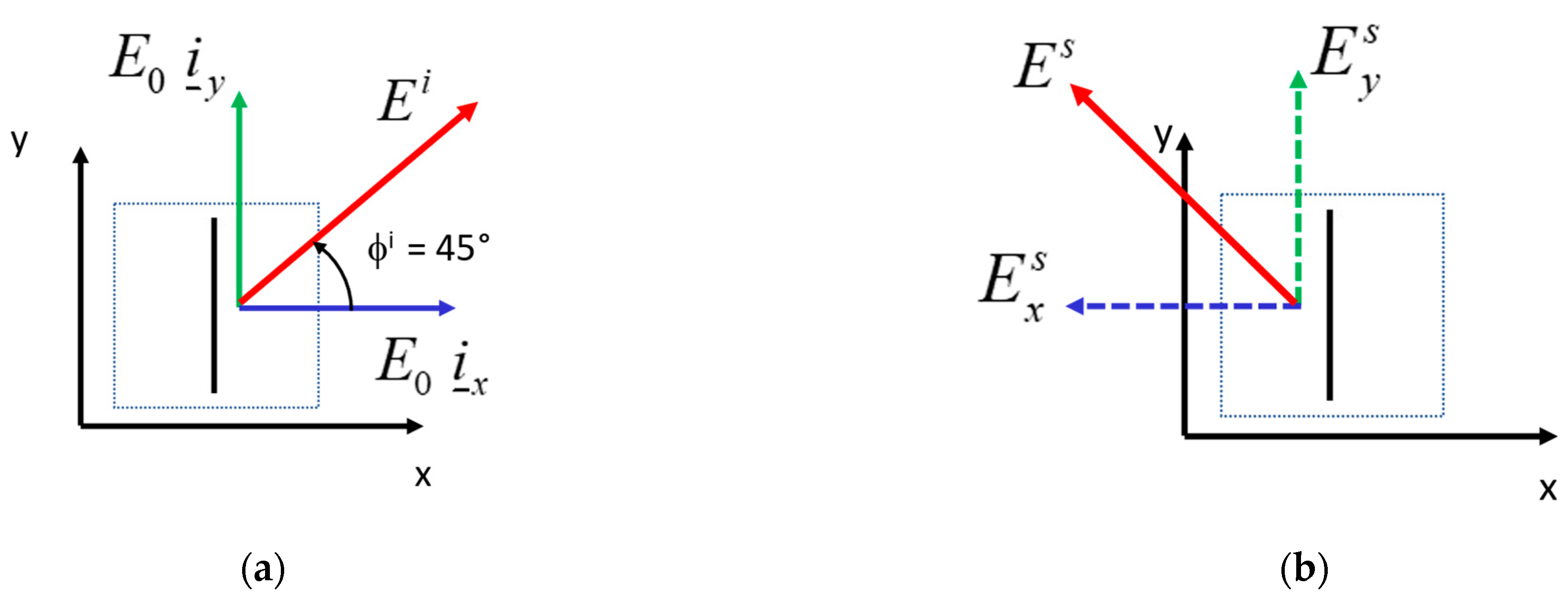
Figure 1. (a) Incident and (b) reflected electric field decomposed in the x and y components of the Electric field.
Electronics 10 00478 g001
Figure 2. Equivalent circuit model for the Artificial Impedance Surface towards (a) x-direction and (b) y-direction.
Electronics 10 00478 g002
Figure 3. Surface impedance of the periodic surface comprising dipole resonator along (a) x–direction and (b) y–direction. The simulated periodicity is equal to 10 mm. The lumped parameters of the circuit models have the following values: Cx = 19.2 fF, Cy = 0.7 fF, Ly = 2.4 nH.
Electronics 10 00478 g003
Figure 4. (a) Amplitude and (b) Phase of the reflection coefficient for x and y polarization. The Artificial Impedance Surface (AIS) is composed by a grounded layer of Teflon (εr = 2.3 − j0.0028) with a thickness of 1.52 mm and a periodic surface comprising dipole resonators.
Electronics 10 00478 g004
Figure 5. (a) Stack-up and unit cell of the simulated Frequency Selective Surface (FSS); (b) Amplitude of the crosspolar reflection coefficient simulated with the periodic method of moments (MoM) for three different azimuthal angles: ϕ = 0°, ϕ = 10°, ϕ = 45°. The AIS is composed by a grounded layer of Teflon (εr = 2.3 − j0.0028) with a thickness of 1.52 mm and a periodic surface comprising dipole resonators.
Electronics 10 00478 g005
Figure 6. Maximum of the amplitude of the crosspolar reflection coefficient as a function of the azimuthal angle for the case of (a) vertical dipole and (b) 45°-tilted dipole. The simulations are performed with a numerical code based on the periodic MoM.
Electronics 10 00478 g006
Figure 7. (a) Stack-up and unit cell and (b) maximum of the amplitude of the cross polar reflection coefficient as a function of the azimuthal angle for the unit cell obtained by the combination of the vertical ad 45°-tilted dipole. The simulations are performed with a numerical code based on the periodic Method of Moments (MoM).
Electronics 10 00478 g007
Figure 8. (a) Amplitude of the crosspolar reflection coefficient simulated for three different azimuthal angles: ϕ = 0°, ϕ = 10°, ϕ = 45° for the unit cell with the vertical and 45°-tilted dipole; (b) pictorial representation of the different sectorial angles in which alternatively one of the two dipoles works.
Electronics 10 00478 g008
Figure 9. Bidimensional false color map of the amplitude of the cross polar reflection coefficient as a function of the frequency and rotation angle ϕ for the combined unit cell.
Electronics 10 00478 g009
Figure 10. (a,c) Maximum of the amplitude of the cross polar reflection coefficient as a function of the azimuthal angle and (b,d) bidimensional false color map of the amplitude of the cross polar reflection coefficient as a function of the frequency and rotation angle for the dual-band and tri-band polarization converter.
Electronics 10 00478 g010
Figure 11. (a) Fabricated prototype of the dual band polarization converter; (b) measurements setup.
Electronics 10 00478 g011
Figure 12. (a) Maximum of the amplitude of the measured cross polar reflection coefficient as a function of the azimuthal angle for the dual-band polarization converter (continuous lines) and for the polarization converter without the 45°-tilted dipoles (dotted lines). (b) Bidimensional false color map of the amplitude of the measured cross polar reflection coefficient as a function of the frequency and rotation angle ϕ for the dual-band polarization converter.
Electronics 10 00478 g012
Figure 13. (a) Cross-polar reflection coefficient of the proposed 4-bit polarization independent and depolarizing unit cell computed at χ = 0° and ϕ i = 45°(b) Bidimensional false color map of the amplitude of the cross polar reflection coefficient as a function of the frequency and rotation angle ϕ for the dual-band polarization converter.
Electronics 10 00478 g013
Publisher’s Note: MDPI stays neutral with regard to jurisdictional claims in published maps and institutional affiliations.