1. Introduction
The problem that contemporary electronics still has to handle is effective cooling of electronic devices [
1,
2,
3,
4,
5]. It is becoming even more important with an increase in the integration scale of semiconductor dies, dissipated power, and power density [
6,
7,
8,
9]. The cooling of semiconductor devices is critical due to self-heating phenomena causing an increment in semiconductor die temperature as a result of current flow across them [
10,
11,
12]. As a result of self-heating, the internal temperature of semiconductor devices may reach values leading to a significant shortening of the device’s lifetime and to its immediate catastrophic failure [
13,
14,
15]. The solutions to reduce the value of the internal temperature of electronic devices are various cooling methods [
5,
16,
17].
In general, cooling methods may be divided into two groups—passive (free cooling) and active (forced cooling) [
16]. Free cooling methods use heat sinks, heat pipes [
18,
19,
20], vapor chambers [
18,
20,
21,
22,
23,
24,
25,
26], liquid chambers [
27], and various types of thermal interfaces —thermoconducting pastes, glues, pads, gels, and phase change materials [
28,
29]. Forced cooling methods mostly make use of fans, but also, liquid cooling systems [
30,
31,
32,
33,
34] and thermoelectric (Peltier) modules [
35,
36] are used.
Forced and free cooling methods may be combined in many configurations of different complexities, costs, and efficiencies [
30,
31,
32,
33,
34]. A cooling system may also operate in the free cooling mode until a certain level of temperature or power is reached, and in the forced cooling mode above that level. From the perspective of an engineer, when designing a cooling system, it is important to choose an optimal configuration of such a system. Computer modelling may help to solve the problem of selecting an optimal cooling system and to design it [
37,
38,
39,
40].
Thermal models allow the computation of the internal temperature of electronic devices at the known value of power dissipated in them. Both compact and detailed thermal models have been proposed in the literature [
37,
38,
39,
40]. Detailed thermal models allow the computation of time–spatial temperature distribution in the modelled device. In turn, compact models allow the computation of a waveform of one averaged internal temperature of the device.
Compact thermal models allow much faster computations, but they do not allow the computation of temperature distribution in the modelled device. In [
41,
42,
43,
44], a method of formulating compact models of semiconductor devices based on the result obtained by solving the heat transfer equation is proposed. In the cited papers, a multipath heat transfer in power modules or LED lamps is taken into account.
In [
1], the problem of modelling the thermal properties of a system composed of an Insulated Gate Bipolar Transistor (IGBT) module, thermal interface, and heat sink is described. Compact thermal models in the form of both the Foster network and the Cauer RC network are used, and the revised method of measurements necessary to determine the thermal models’ parameters is discussed. In turn, in [
45] a similar problem is considered for a double-side cooled power module. In the cited paper, the results of the analyses performed with the Finite Element Method (FEM) are presented and discussed. It was shown that a multipath heat transfer should be taken into account.
The transfer of heat generated in electronic devices to the surroundings takes place by means of three mechanisms [
10]: heat conduction, convection, and radiation. As indicated in [
46,
47], the efficiency of each mentioned way depends on the ambient temperature and internal temperature of the analyzed device.
Most compact thermal models proposed in the literature are linear and do not take into account the influence of temperature on the effectiveness of semiconductor devices’ cooling. In the authors’ previous papers [
46,
48], nonlinear thermal models of semiconductor devices operating in free cooling systems were proposed. In turn, in [
47] a method of modelling a multipath heat transfer was proposed.
As it results from the literature review, the problem of modelling the thermal properties of forced cooling systems is not analyzed deeply. Particularly, the influence of the power dissipated in the cooled device and the parameters characterizing the efficiency of the components of the cooling systems are typically omitted. Therefore, investigations on the properties of such cooling systems should be performed.
In this paper, the results of such analyses illustrating the influence of selected factors on the parameters of a compact thermal model of selected cooling systems of electronic devices are presented. Investigations were carried out for various structures of cooling systems, including heat sinks, fans, thermal pads, and Peltier modules. It was proved that the nonlinear thermal models proposed in the paper reflect well the properties of the investigated cooling systems.
In
Section 2, the used measurement method is described.
Section 3 presents the investigated cooling systems. In
Section 4, the elaborated thermal model is presented.
Section 5 describes the method of parameter estimation.
Section 6 presents the obtained results of the measurements and modelling of the considered cooling systems.
2. Measurement Method
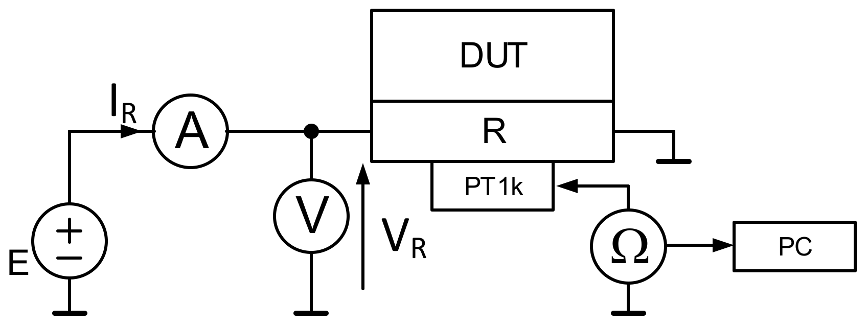
In order to perform investigations, several cooling systems were selected. The general scheme of the experimental setup is shown in
Figure 1.
As a heat source, a 3.6 Ω thick film resistor R with the ceramic substrate (Al
2O
3) GBR-666/12/2 by Telpod, Kraków, Poland [
49] was used. This resistor has dimensions of 38 × 25 × 1 mm, and it is supplied from a voltage source E. Current I
R and voltage V
R on the resistor were measured using an ammeter and a voltmeter, respectively. The power dissipated in resistor R is equal to the product of I
R and V
R. The cooling systems selected for the investigations, presented in
Figure 1 as DUT (Device under Test), are described in the next section.
Temperature T
R of resistor R was measured with a PT 1000 platinum temperature sensor (thermoresistor), Proffuse PT1000-550 (TME, Łódź, Poland) [
50], glued to the surface of the resistive path in the middle of the resistor (see
Figure 2). This thermoresistor is characterized by a tolerance of 0.3%, and the temperature coefficient of resistance
α = 3850 ppm/K. The thermoconducting glue Amepox Microelectronic Thermopox 85CT (Amepox Microelectronic, Łódź, Poland) with a thermal conductivity in the range from 1.4 to 2.2 W/(m∙K) and an electrical resistivity higher than 5 MΩ (with a thickness of over 0.1 mm) was used. The PT 1000 sensor resistance
RT was measured using an ohmmeter, UNI-T UT804 (Uni-Trend Technology (China) Co., Ltd., Dongguan, China). The temperature of this sensor was computed using the following formula:
where
RT0 is the sensor resistance at reference temperature
T0 = 273.15 K. It was assumed that the PT 1000 sensor has a linear characteristic. A PC, the UNI-T UT804 multimeter, and the dedicated software were used to record a transient thermal response
TR(t) of the considered resistor co-operating with the investigated cooling systems.
In order to measure the thermal parameters of this device operating in different cooling systems, the following steps should be performed:
- a)
Measurement of resistance RT1 of the thermoresistor at the steady state when the investigated resistor is not fed (IR = 0);
- b)
Computation of the value of temperature TR1 corresponding to resistance RT1 using Equation (1);
- c)
Feeding this resistor with heating power until the steady state is obtained; in this step, the values of voltage VR and current IR are measured at the steady state, whereas waveform RT(t) is recorded using a multimeter and a PC;
- d)
Computation of the waveform of the transient thermal impedance of the investigated resistor using the following formula:
The value of transient thermal impedance Zth(t) at t → ∞ is equal to thermal resistance Rth.
3. Investigated Cooling Systems
Investigations were performed for the considered power resistor co-operating with five different cooling systems. One of them belongs to free cooling systems, whereas the other four to forced cooling systems. These cooling systems are characterized below.
The simplest free cooling system, denoted further as system A, contains only the investigated resistor. It is mounted as it is shown in
Figure 2. In turn, the cooling system denoted as system B contains the resistor, an active heat sink, and a self-adhesive thermo-conducting pad used as a thermal interface. System C contains the tested resistor, a heat sink, and a silicon paste applied as a thermal interface. System D contains the investigated resistor, an active heat sink, and a self-adhesive thermoconducting pad operating as a thermal interface. System E contains the tested resistor, the Peltier module, an active heat sink, and two self-adhesive thermoconducting pads as thermal interfaces.
In cooling systems D and E, the Peltier module (Ferrotec Nord, Moscow, Russia) TM–71-1.4-8.5MS was used. According to the producer’s data [
51], the dimensions of this module are 30 mm× 30 mm × 3.4 mm, whereas the maximum feeding current
Imax = 8.5 A, the maximum feeding voltage
Vmax = 8.2 V, the maximum dissipated power
Pmax = 41.8 W, and the maximum difference in temperature between the two module sides
ΔTmax = 71 °C. In systems B, D, and E, a double-side self-adhesive thermoconducting pad, THERMOPAD-6X1X30 (TME, Łódź, Poland) [
52], with thermal conductivity
λ = 6 W/(m∙K) was used. The pad is 1 mm thick (
d = 1 mm), and its nominal thermal resistance can be computed using the following formula:
where
S is the area of this pad.
The view of cooling system D is shown in
Figure 3.
The Peltier module is fed from the current source IP. The module’s current IP and voltage VP are measured with an ammeter and a voltmeter. The power dissipated in this module is equal to the product of current IP and voltage VP.
In cooling systems B, C, and E, the PC microprocessor active heat sink Arctic Freezer 34 eSports Duo 2 × 120 mm [
53] containing a heat sink and a fan were used (see
Figure 4). Systems B and C differ from each other in the type of thermal interface used between the resistor and the active heat sink, which in system B is the pad described above and in system C the thermoconducting paste Electrolube EHTC10S of thermal conductivity
λ = 0.9 W/(m∙K). In order to hold the investigated cooling system in a fixed position, systems B, D, and E were held in a vice using teflon separators. In order to fix the heat source in its place in system E, a back frame coming as a part of the Arctic cooling set was used. To achieve the appropriate value of the press force, two thermally insulating separators were used.
The Arctic cooling set is constructed with the use of a heat sink made of a stack of aluminum fins attached to four heat pipes and two fans of 120 mm diameter each. The base of the set is constructed with an aluminum block with heat pipes going across it [
50]. In order to achieve the best possible heat conduction from the heat source to the heat sink, the heat pipes are shaped and machined in the so-called direct contact technique.
The two fans of the Arctic cooling set are supplied from the external voltage source. The voltage on the fans is controlled with a voltmeter. In this configuration, the speed of the air is measured.
The view of cooling system C is shown in
Figure 5, whereas the view of system E in
Figure 6.
4. Thermal Model
In order to analyze the thermal properties of the cooling systems under investigation, a nonlinear thermal model of the investigated cooling system was proposed. This model allows the computation of internal temperature Tj of the electronic device at the known power dissipated in it, taking into account the influence of ambient temperature power loses in the modelled device and in the parts of the cooling system (e.g., Peltier module) and the speed of the air around the heat sink on the efficiency of heat removal.
The model has the form of a subcircuit for Simulation Program with Integrated Circuits Emphasis (SPICE). At its formulation, the electrical–thermal analogy presented (e.g., in [
39,
54,
55]) was applied. In this analogy, voltage represents temperature; current, power; resistance, thermal resistance; and capacitance, thermal capacitance. The formulated model is based on the idea proposed in [
46,
56]. According to this idea, the nonlinear Foster network is used to model the dependence of the transient thermal impedance of this device on the dissipated power. Due to the fact that an influence of the considered parameters on thermal resistances was observed and such an influence was not observed for thermal capacitances, in the model proposed in this paper, linear thermal capacitances and nonlinear thermal resistances were used.
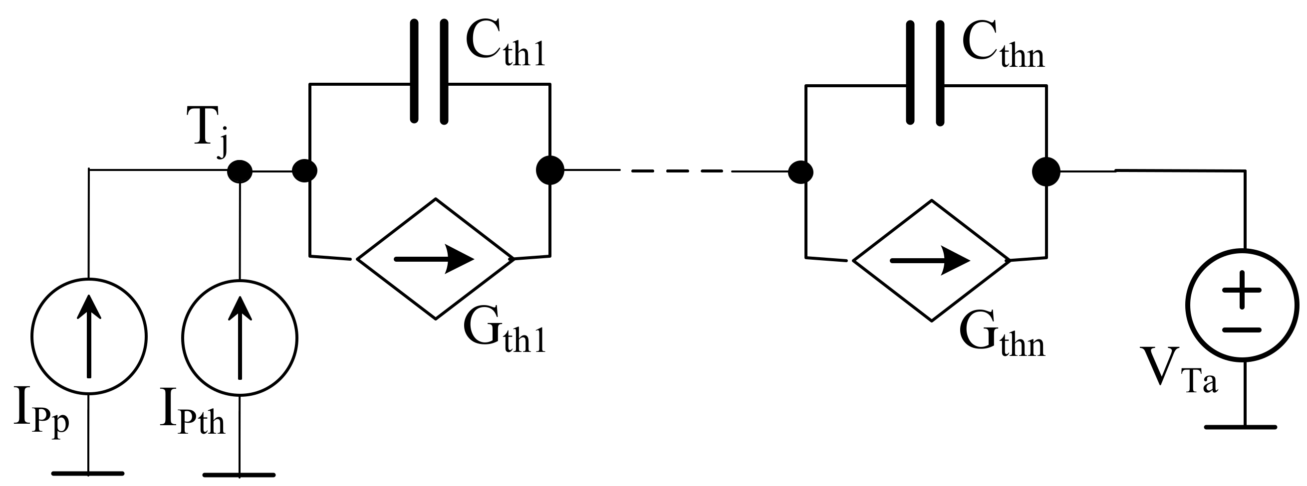
A network representation of the proposed nonlinear thermal model of the electronic device is shown in
Figure 7.
In this model, current source IPth represents the power dissipated in the modelled device; current source IPp, the power dissipated in the Peltier module; voltage source VTa, ambient temperature; controlled current sources Gth1, …, Gthn, the components of thermal resistance of this device; and capacitors Cth1, …, Cthn, thermal capacitances of the components on the heat flow path.
The ability of the modelled device to dissipate heat generated inside this device with all the mechanisms of heat transfer is characterized by transient thermal impedance
Zth(t), typically given in a form of the formula [
39,
54,
55]
where
Rth is thermal resistance,
ai are coefficients corresponding to thermal time constants
τthi, and
N is the number of thermal time constants.
Thermal capacitances in this model depend on the kind of material and mass of the components occurring in the heat flow path of the cooling system [
10]. The parameters of the components of the cooling system mentioned here do not change much with temperature changes. Therefore, capacitors modelling thermal capacitances are linear in the proposed model. In turn, thermal resistances
Rth in the model depend on many factors (e.g., the construction of the cooling system applied and power losses in the cooled device). These thermal resistances are characterized in the latter part of this section.
Changes in the values of thermal resistance are modelled by controlled current sources
Gth1, …,
Gthn. The current of such a source is given by the following formula
where
VGi denotes the voltage on current source
Gthi.
Thermal capacitances are given by the following formula:
In the presented model, the dependence of
Rth on dissipated power
pth is described with the use of the empirical formula of the following form:
where
Rth0 denotes the minimum value of thermal resistance, whereas
Rth1,
b, and
c are model parameters. The values of parameters
Rth0, Rth1, b, and
c depend on the configuration of the investigated cooling system.
When the Peltier module is a part of the cooling system, parameter
ax depends on the power feeding the module according to the formula
where
pP means the power feeding the Peltier module and
αthP and
bP are parameters of the thermal model of the module.
In turn, when a fan is used in the cooling system,
bx depends on the speed of the airflow generated by the fan according to the formula
where
βthv and
bv are parameters of the thermal model characterizing the influence of airflow speed
v on thermal resistance.
5. Model Parameters Estimation
In order to practically use the proposed model, the values of the parameters occurring in this model should be estimated. The estimation procedure consists of three steps. First, the waveforms of the transient thermal impedance of the investigated device are measured with the use of the method described in
Section 2. These measurements should be performed for the used cooling system at different values of the power dissipated in this device.
In the second step, parameters
Rth, N, ai, and
τthi, occurring in Equation (4), are estimated with the use of the ESTYM algorithm described in the paper [
39]. The values of parameters
Rth, ai, and
τthi obtained at the highest value of the dissipated power are used to compute the values of thermal capacitances C
thi using Equation (6). Additionally, the values of parameters a
i are used to describe the output current of sources
Gthi.
In the third step, the measured dependences Rth(pth) are approximated using the formula (7) for the used cooling systems. For the maximum value of power pth, Rth(pp), and Rth(v), the parameters occurring in Equations (8) and (9) are estimated using the measured dependences. For cooling systems without the Peltier module, parameter αthP = 0, whereas for such systems without fans, parameter βthv = 0.
Figure 8 illustrates the dependence of the thermal resistance of a power resistor placed horizontally and operating without any additional cooling (system A) on power
pth dissipated in this resistor.
As may be noticed, dependence is a monotonically decreasing function. In the considered range of the dissipated power, thermal resistance decreases by about 25% (from 29 K/W to 22 K/W). The observed dependence is a result of a rise in the efficiency of natural convection on the surface of the investigated resistor with an increment of its temperature.
Figure 9 presents the measured and modelled dependences of the thermal resistance of the resistor attached to the cold side of the Peltier module with the use of a thermal pad (system D). This figure shows also an influence of the power dissipated in the Peltier module on the thermal resistance of the investigated resistor. The results obtained for the Peltier module with no supply (
IP = 0) are marked with blue color, whereas the results for the module’s current
IP = 1 A are marked with red color.
For both values of the module’s current, thermal resistance is a decreasing function of the dissipated power. In particular, at IP = 1 A an influence of the value of the dissipated power on thermal resistance is clearly visible. It results from the fact that the hot side of the Peltier module was cooled in a way of natural convection and no heat sink was attached to it. Additionally, in the considered cooling system, power was dissipated both in the resistor and in the Peltier module, causing a bigger growth of the resistor temperature than in the case when this module was not supplied. At low values of power p, the power dissipated in the Peltier module is a dominant component of the whole power dissipated in the investigated cooling system. It is worth noting that attaching the Peltier module using a thermal pad allowed the reduction of the thermal resistance value even by 50% compared with a resistor with no cooling system attached. It is probably a result of a growth in the heat exchange area.
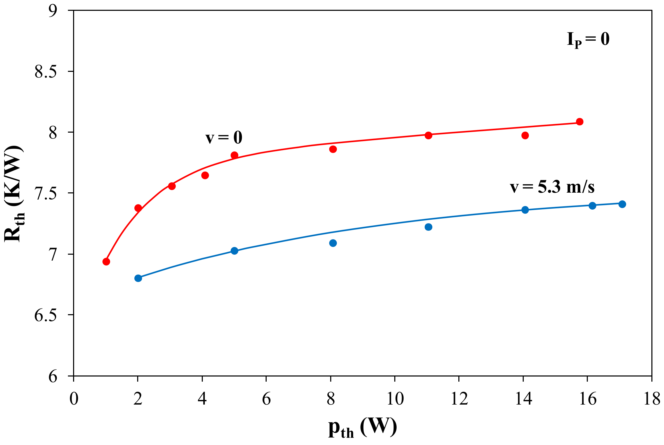
The results of investigations on the next cooling system (system B) containing the considered resistor, the thermal interface, and a heat sink with a fan are shown in
Figure 10 and
Figure 11.
Figure 10 shows the dependences of the thermal resistance of the resistor operating in the analyzed system on the power generated in the resistor at two values of the airflow speed equal to 0 (blue) and 5.3 m/s (red).
The presented dependence Rth(pth) is a decreasing function in the whole range of power pth when the cooling system operates in the natural convection (v = 0) conditions, whereas at operation in the forced convection conditions (v = 5.3 m/s), an increasing function Rth(pth) is obtained for power pth > 3 W. Such a character of Rth(pth) changes indicates that in the natural convection conditions, heat convection has a dominant influence on thermal resistance, but in the forced cooling conditions, it is heat conduction. It is worth noting that applying forced cooling allows the lowering of the thermal resistance of the resistor even by 35%.
Figure 11 presents the dependence of the thermal resistance of the resistor incorporated into the investigated cooling system on the airflow speed at power
pth = 35.5 W dissipated in the resistor.
It can be noticed that dependence Rth(v) is a decreasing function in the whole analyzed range of the airflow speed changes. It is important to point out that the biggest change in thermal resistance is observed at low values of airflow speed v. For example, a change of the airflow speed in the range from 0 to 1 m/s causes a decrease of Rth by 25%, whereas a change from 1 to 5 m/s causes a change of Rth only by 6%.
Figure 12 and
Figure 13 illustrate the thermal properties of the investigated resistor cooled by an active heat sink. As the thermal interface between the resistor and the heat sink, the silicon paste is applied (system C). In
Figure 12, the dependence of the thermal resistance of the resistor operating in this cooling system on the power generated in it at two values of airflow speed
v equal to 0 and 5.3 m/s is shown.
As can be noticed, dependence Rth(pth) is an increasing function at airflow speed v = 5.3 m/s, and it is a decreasing function at v = 0. The considered increment in airflow speed causes over a triple decrease in the value of the thermal resistance. At v = 0, an increase in the dissipated power from 5 to 80 W causes a decrease in the value of Rth by 25% due to an increase in the efficiency of heat convection as a result of a higher temperature of the surface of the resistor. In turn, at v = 5.3 m/s, an increase in the dissipated power from 15 to 260 W causes an increment in the Rth value exceeding by even 40%. This change is a result of a decrease in the thermal conductivity of the heat sink due to a higher temperature of the resistor.
The results presented in
Figure 12 prove that applying the silicon paste instead of a thermal pad allows the reduction of the thermal resistance value even by about 2.5 K/W, which means that it is possible to raise the power dissipated in the resistor even three times.
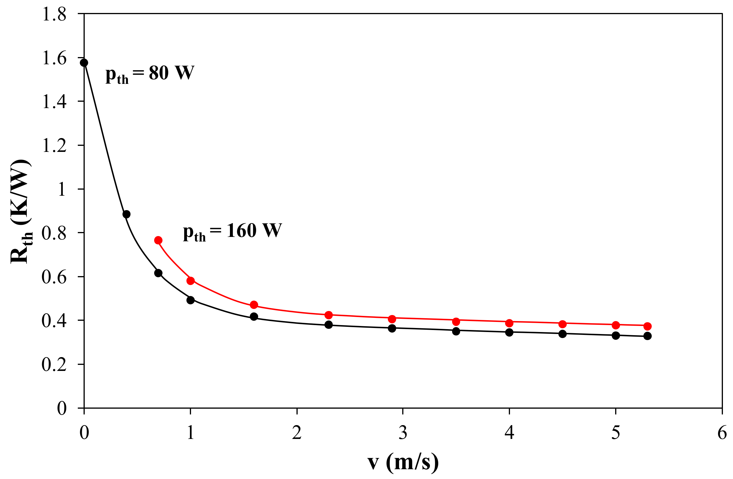
In
Figure 13, the dependence of the thermal resistance of the resistor on the airflow speed at two values of power equal to 80 and 160 W is shown.
As can be seen, an increase in the airflow speed causes a decrease in the thermal resistance of the resistor. In the considered range of changes of the airflow speed, Rth decreases from 1.6 K/W to 0.3 K/W. The biggest change is observed in the range of speed from 0 to 1.5 m/s.
Figure 14 and
Figure 15 show the measurements and modelling results of the cooling system containing the resistor selected for the experiment, the Peltier module, an active heat sink, and two thermal pads (system E). In
Figure 14, the dependences of the thermal resistance of the resistor on the power dissipated in the resistor without feeding the Peltier module and two values of the airflow speed equal to
v = 0 and
v = 5.3 m/s are presented.
As can be seen, the obtained values of thermal resistance are highest of all the considered systems of forced cooling. This is a result of the use of additional layers on the heat flow path—two thermal interfaces and the Peltier module. Dependence Rth(pth) is an increasing function in the whole range of changes of the dissipated power. An increment in the airflow speed causes an increase in thermal resistance even by 10%.
Figure 15 illustrates the influence of the current supplying the Peltier module on dependence
Rth(pth) at two selected values of current
IP feeding this module.
For both IP values, increasing dependences Rth(pth) were obtained. In the figure, the negative Rth value for power pth < 2 W draws attention. It is a result of applying the Peltier module, whose cold side is in contact with the resistor via a thermal pad. In this range, the power dissipated in the resistor is so small that an increase in its temperature caused by self-heating is smaller than a temperature drop caused by the Peltier module.
For each of the cooling systems operating at different conditions, the values of thermal capacitances Cthi were estimated. The number of these capacitances depends on the structure of the considered system. For example, in the model of system B-2, thermal capacitances occur, and in the model of system E-3, thermal capacitances occur. The values of particular thermal capacitances describing the properties of the same cooling system change not more than by a small percentage with changes of the power dissipated in the cooled device.
6. Results
In order to validate the proposed thermal model, some measurements and computations of temperature of a power resistor co-operating with various cooling systems were performed. The results of the investigations are presented in the figures shown in the latter part of this section. In all these figures, points denote the results of the measurements, whereas lines, the results of the computations.
Figure 16 illustrates the waveforms of temperature
TR(t) of the resistor operating in system A and excited with a power step of various values of p
H equal to 2.5 W, 4.4 W, and 5.5 W.
It can be easily noticed that the computed waveforms TR(t) are modelled with a very good accuracy for all the power values. The time necessary to achieve the steady state does not exceed 500 s, and the resistor temperature in the steady state at the highest value of power reaches almost 150 °C.
In
Figure 17, the computed and measured waveforms of the considered resistor temperature for three different ways of power generation in the investigated cooling system D are presented. Blue color corresponds to the case when power
pH = 8.4 W is generated only in the resistor, black color when power
Pp = 1.7 W is generated only in the Peltier module, and red color when power is generated both in the resistor (
pH = 6.1 W) and in the Peltier module (
Pp = 2 W).
Analyzing the obtained waveforms TR(t), it can be noticed that when power is generated only in the Peltier module, in a short time (between 6 and 60 s) after switching the cooling system on, the temperature of the resistor decreases below the ambient temperature. Later, this temperature increases as a result of heat generation in the Peltier module and heating up of the resistor by the module. When power is generated only in the resistor, the obtained values of temperature TR are highest. When the power of a similar overall value is generated in the resistor and in the Peltier module, the resistor temperature is lower than when the power is generated only in the resistor.
It is worth noting that applying the Peltier module in the cooling system allowed the improvement of the efficiency of heat dissipation, but simultaneously, the power generated in the cooling system increased, which may cause an additional rise in temperature in the cooled device. In the analyzed cooling system, the steady state is reached after about 1000 s.
In
Figure 18, the waveforms of the internal temperature of the power resistor cooled by a heat sink equipped with a fan (system B) is shown. Waveforms
TR(t) correspond to two values of the power generated in the cooled resistor (25 W and 37.7 W) and two values of the airflow speed
v (0 and 5.3 m/s).
As can be seen, at a higher speed of the considered speeds of the airflow, temperature TR stabilizes after 1 min after the measurements start. In contrast, in the natural convection conditions (v = 0), the time of temperature TR(t) stabilization exceeds 1 h. At power pth = 25 W generated in the tested resistor, due to the application of forced cooling, temperature TR in the steady state is about 35 °C lower than that for power pH = 37.7 W.
Figure 19 illustrates the waveforms of the internal temperature of the resistor selected for the experiment heated with a power of 81.7 W at two values of the airflow speed equal to 0 (blue color) and 5.3 m/s (red color).
Comparing the results obtained for both values of v, it can be noticed that the airflow speed significantly influences both the temperature of the resistor at the steady state and the time of TR(t) stabilization. At a higher value of the two considered values of the airflow speed, this time is equal to merely 30 s and 1 h at v = 0. The values of TR temperature at the steady state differ from each other even by about 100 °C.
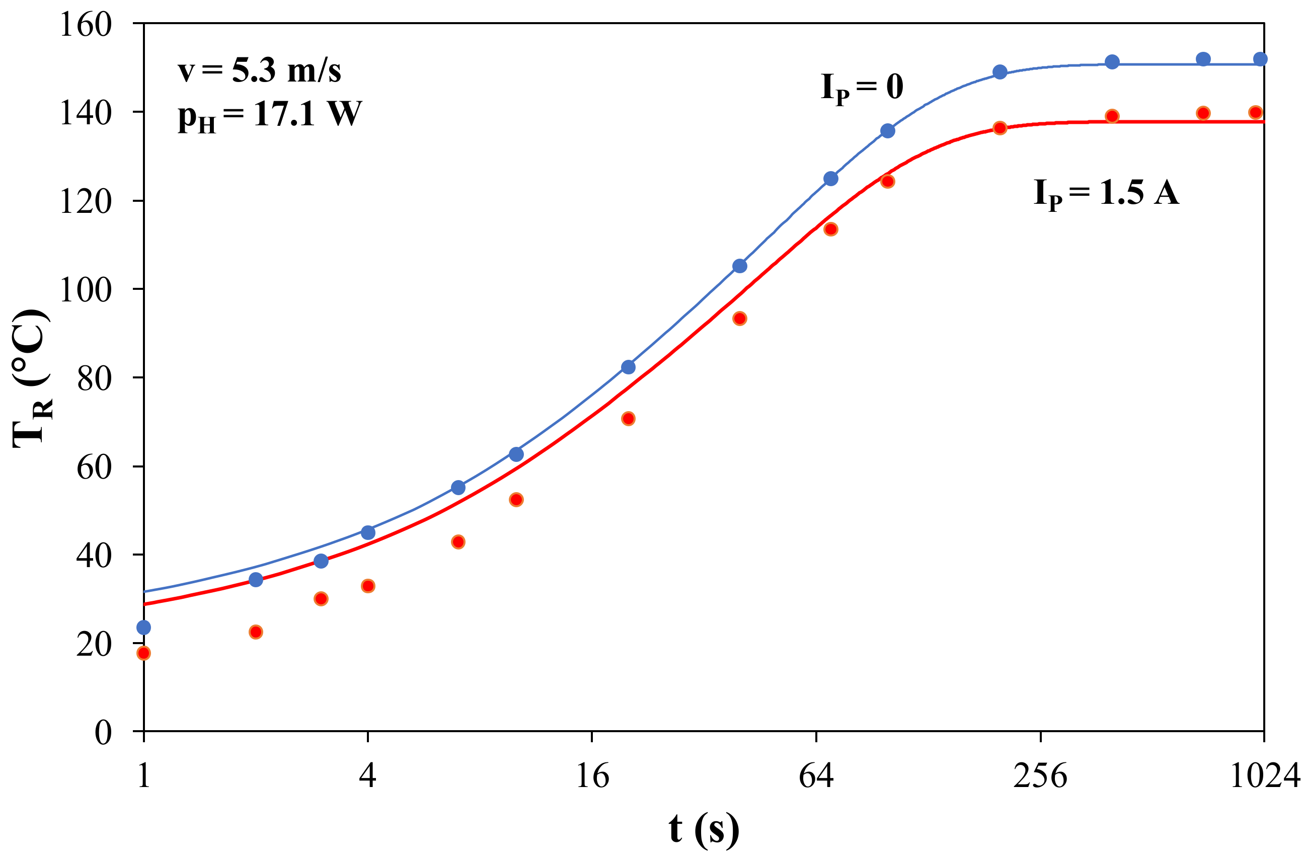
In
Figure 20, the measured and computed heating curves of the internal temperature of the resistor selected for the experiment with cooling system E composed of an active heat sink, the Peltier module, and two thermal pads at two values of the Peltier module’s current
IP = 0 and
IP = 1.5 A are shown.
As can be seen, the temperature stabilization time is about 400 s in both cases. Feeding the Peltier module with current IP = 1.5 A causes a 12 °C drop in the resistor temperature.
Analyzing the results of the investigations presented above, one can conclude that the construction of the cooling system significantly influences the ability of an electronic device to dissipate the heat generated in this device.
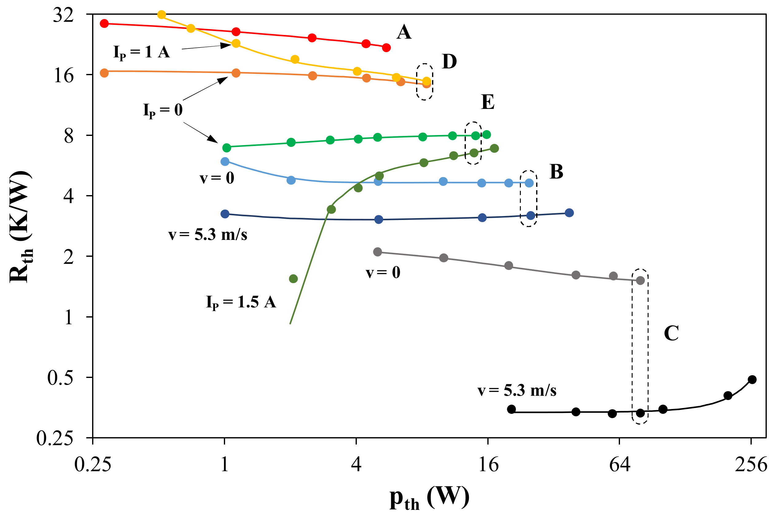
In
Figure 21, the measured and computed dependencies of the thermal resistance of the considered resistor on the power dissipated in this device are presented. In this figure, the results related to each cooling system are marked in the following way: system A, the investigated resistor with no additional cooling devices; system D, constructed with a thermal pad and the Peltier module; system E, constructed with two thermal pads, the Peltier module, and an active heat sink; system B, constructed with a thermal pad and an active heat sink; system C, constructed with a thermoconducting paste and an active heat sink. The curves in the figure are also marked with the values of the parameters characterizing the cooling process.
Analyzing the results of the investigations presented in this paper, one can see that the proper selection of a cooling system allows the reduction of the values of the thermal resistance of the resistor selected for the tests almost 100 times. It can also be noticed that the maximum power that can be dissipated in the resistor without exceeding its maximum allowable temperature goes up from 5 W to over 250 W.
Obviously, cooling was least efficient in system A (i.e., in the case of the resistor without any additional components improving the heat dissipation in it). Adding the Peltier module and a thermal pad to this system allows the improvement of the efficiency of cooling due to a growth of the heat convection area. A further drop of thermal resistance is achieved after adding an active heat sink on top of the cooling system. As it turned out, the removal of the Peltier module and the thermal pad from the cooling system improved the investigated device’s cooling efficiency. It is worth noting that the thermal pad applied is responsible for an important part of the overall thermal resistance. Replacing this pad with the silicon paste allows the reduction of thermal resistance even by 2 K/W.
It is also easy to observe that in the operation of the cooling system in the free convection conditions when neither the Peltier module nor the fan is fed, dependence
Rth(pth) is a decreasing function. It allows the conclusion that the dominant component of thermal resistance is connected to heat convection. According to the equation given (e.g., in [
10,
57,
58]), the efficiency of heat removal with heat convection is proportional to the difference between the temperatures of the cooled surface and the cooling fluid. Of course, the temperature of the cooled surface goes up with an increase in the dissipated power at the fixed cooling conditions. In turn, in the forced cooling systems used, where the Peltier modules or a fan is supplied, dependence
Rth(pth) is an increasing function. This character of the considered dependence indicates that the dominant component of thermal resistance is connected to heat conduction, whose efficiency for the materials used to construct heat sinks decreases with temperature rise. According to the considerations given (e.g., in [
10,
57,
58]), the efficiency of heat removal with heat conduction is a decreasing function of the device temperature. This temperature goes up with an increase in the dissipated power.
A good match of the results of the measurements and computations is obtained for all the considered cooling systems, which proves that the proposed model equations are correct.
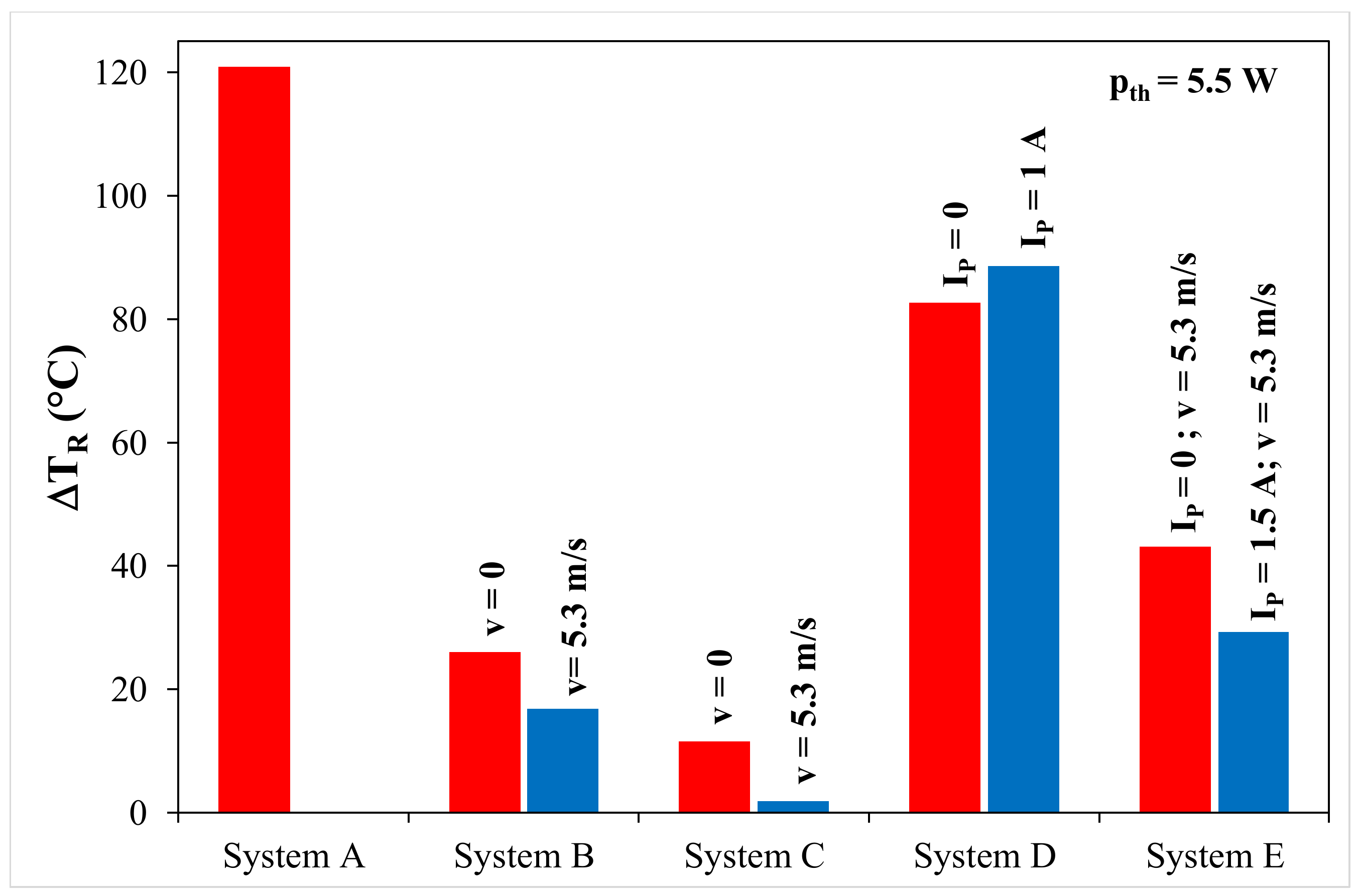
In order to compare the effectiveness of the investigated cooling systems, the values of an excess of the temperature of the considered resistor over the ambient temperature at the fixed value of the dissipated power
pth = 5.5 W are presented in
Figure 22.
It is easy to observe that the highest value of the resistor temperature is obtained for system A, without any components improving the cooling. In this case, ΔTR = 120 °C. The most efficient is the cooling of system C, in which the value of ΔTR does not exceed 2 °C. It is shown that the considered forced cooling systems can make it possible to reduce temperature excess ΔTR by even 60 times in the device.
From the point of view of the designer of cooling systems, not only is the efficiency of these systems important, but also the costs and dimensions of the used components should be taken into account. In the considered cooling systems, the cost of a thermal pad is equal to 1.5 USD; the Peltier module, 23 USD; and the active heat sink, 51 USD. The volumes of these components are 0.9 cm3, 3.06 cm3, and 2005.2 cm3, respectively. It is shown that in order to obtain the best cooling efficiency, the active heat sink is needed, which is characterized by the highest cost and the greatest volume.
7. Conclusions
In this paper, a way of modelling the thermal properties of an electronic device operating in the free convection and forced convection conditions is presented. A form of a nonlinear compact thermal model and equations describing the influence of selected factors on the thermal resistance of the electronic device are proposed. Validation of the proposed model was performed experimentally in five cooling systems. For each system, a good match of the results of the measurements and computations was achieved. The differences between these results typically do not exceed 5%.
The results presented in the paper prove that the selection of cooling system components influences the ability to dissipate heat generated in the cooled device, which is characterized by thermal parameters. It was shown that additional components of the cooling system do not always improve the efficiency of heat dissipation. This concerns in particular the use of the Peltier module and thermal pads. Thermal pads provide electrical insulation between cooling system components, but they also cause a significant rise in thermal resistance, even equal to about 2 K/W.
The performed measurements and computations show that applying a cooling system based on natural convection provides efficient dissipation of the heat generated in the electronic device, but systems based on forced convection provide further reduction of thermal resistance. The value of this parameter can be reduced by even 100 times, whereas the dissipated power can increase by even 50 times due to the modification of the cooling system.
It was shown that with the power generated in the cooled device, the current supplying the Peltier module and the airflow speed significantly influence the thermal resistance of the cooled device. This influence was modelled with exponential functions, which allowed us to obtain a very good match of the results of the measurements and computations.
It is worth noting that in forced cooling systems, the dependence of thermal resistance on the dissipated power is a monotonically increasing function, and in free cooling systems, it is a decreasing function. This results from the dominant influence of convection on heat dissipation in such systems and thermal conduction in forced cooling systems.
For the investigated cooling systems, the time of temperature stabilization in an electronic device is much longer in free cooling systems than in forced cooling systems. This time varies by even 100 times when comparing both the considered groups of cooling systems.
The results of the investigations presented in the paper may be used by designers of cooling systems of electronic devices. These results may make easier the selection of the cooling system components of an electronic device appropriate for the dedicated application.
The computations and measurements were performed for the resistor with dimensions of 38 mm × 25 mm × 1 mm, but the influence of the considered factors on the thermal parameters of the electronic devices would be quantitatively the same for such devices with different dimensions. Particularly, the influence of the dissipated power on the thermal resistance of power semiconductor devices can be described with an exponential function [
47].
In further considerations, the usefulness of the thermal model proposed in this paper for power semiconductor devices will be analyzed. Additionally, the influence of the dimensions of the components of a forced cooling system on the thermal resistance of the cooled electronic device will be investigated. A problem that is also worth considering in further investigations is the influence of the power consumed by the active components of forced cooling systems (Peltier modules, fans) on the running costs of the selected electronic devices.


