Article

Magnetic Elastomer Sensor for Dynamic Torque and Speed Measurements

Department of Electrical Apparatus, Technical University of Sofia, 1156 Sofia, Bulgaria
*
Author to whom correspondence should be addressed.
Electronics 2021, 10(3), 309; https://doi.org/10.3390/electronics10030309
Submission received: 30 December 2020 / Revised: 19 January 2021 / Accepted: 23 January 2021 / Published: 28 January 2021
(This article belongs to the Special Issue Recent Advances in Electromechanical Systems)

Abstract

:
In this paper is proposed a dynamic torque, rotational speed, and shaft position sensor. It is built of magnetic elastomer coating directly applied over a rotating shaft. The sensor is used for precise measurements of changes in torque and speed, and it is usable at high rotational speeds, directly on the device shaft. The sensor is based on magnetic elastomer material deformation and the corresponding change in magnetic field amplitude and direction. The proposed sensor design is simple and can acquire reliable readings for a wide range of rotational speeds. Sensor design consists of the following: magnetic elastomer coating with nanoparticles, in which, elastomer is used for a sensing convertor; magneto-resistive linear field sensor; and microprocessor unit for calibration and control. Numerical and experimental test results are demonstrated and analyzed. Sensor implementation aims to meet magnetic mechatronic systems’ specific requirements.

1. Introduction

The precise measurement of static and dynamic mechanical torques is of great importance for many applications. Static torque measurements are required at non-rotational shafts or for those rotating with low peripheral speeds. Typical applications are in sensors for electrical machines, e.g., blocked rotor testing [1], automobile steering wheel sensors [2], robotics arm joints [3,4,5,6], leaver and beam deformation sensors [6], etc. Dynamic torque sensing is much more complicated mainly because of the required deviation of immobilized sensor output and rotating shaft. Dynamic torque sensors’ principles of operation are based mainly on electric-tensoresistive strain gauges [2], acoustic interference [7,8], magnetic permeance and reluctance effects [9,10], and optical polarization [10,11]. Nevertheless, in these existing technologies, the connection problem with the rotating sensing element is not satisfactorily solved, especially for transient modes.
Depending on the torque sensing element’s location, two principal types of design architectures are employed [12,13], the first one uses a directly attached sensor element on the rotating shaft, where readings are transmitted to the information channel by wire brushes, inductive coupling, or even by wireless radio transmitters. Most of the electric-tensoresistive strain gauges are connected this way. Electric power supply is provided to the directly attached sensor elements and corresponding electronic modules, e.g., wire brush contact or inductive coupling connection [4,14,15].
The second principal torque sensor design architecture type uses an emitted physical field quantity (acoustic, optical light, electromagnetic) from a static (non-rotating) emitter toward the rotating shaft where specially designed sensing material passively or actively modulates the input field flux quantity. The modulated signal is received and encoded by a non-rotating receiver [14,15,16,17,18,19]. The second sensor design architecture type eliminates the direct connection problems of attaching wires or optical fibers to the rotating shaft under observation. This way, the sensing equipment impact over the testing process is minimal. However, open-field interaction is much more vulnerable to outer noise sources such as vibration [20], electromagnetic interference, and thermal [20,21,22] or other environmental fluctuations. The stability of an open-interaction channel can be improved by eliminating half of the open transmission path by placing an active emitter on the rotating shaft. This emitter must be simple, compact in size, and light weight enough to be placed on the site of operation [17,18,19]. Magnetic elastomer deformation sensors are of such a kind where shaft deformation caused by torque load is absorbed by the pre-magnetized elastomer material coating (Figure 1b) or magnetic permeable elastomer material (Figure 1a). Material deformation caused by torque changes leads to a measurable change in its magnetic properties. Based on recent analytical considerations, the pre-magnetized sensor design (Figure 1b), where the magnetic elastomer is an active magnetic field source tracked by a distant receiver such as a linear magnetic field probe, is much more promising [10,11,12,13,14,15].
Magnetic elastomer soft composites are smart materials with many potential applications, not limited to sensors only, e.g., in robotics [3,4,5,6], automation [21], transportation [23], power conversion [22], electronics, additive manufacturing [24], healthcare [25], and many others. Such a wide field of applications is due to their controllable physical properties, which are magnetically conjugated.
Magnetic elastomer composites [26,27,28,29,30,31,32,33] are generally produced from three primary ingredients, first elastomer carrier also called composite matrix, magnetic filler particles, and a wide variety of supplementary additives, including plasticizers, coloring agents, coupling agents, and surface-active substances [32,33]. The magnetic properties of magnetic elastomers are created from micro- and nano-sized magnetic particles of the filler, dispersed in a polymeric viscose non-magnetic composition matrix [34,35,36,37,38,39,40,41,42]. Elastomer soft composites carriers have been fabricated from various types of matrix polymer materials [31], including carbon based (PE, PP, PVC, PS, PTFE), silicone polymers, and even flour based. The thermal and mechanical properties of such compositions are determined from carrier properties, because of the bounding function of the matrix material and its relatively high volumetric content (50–99%) compared to the whole composition volume [31,41]. Mechanical deformation properties are determined from elastomer carrier. Magnetic particles of the filler are volumetrically dispersed in the carrier and are responsible for general magnetic properties. These are produced from micro-sized (1 to 100 µm) and nano-sized (5 to 900 nm), soft and hard magnetic materials. Micro-sized fillers are often based on iron particles (5 to 100 μm) with a volumetric concentration from 10% to 50%, at which compositions generally exhibit soft magnetic behavior with low magnetic relative permeability, µr < 10 [43,44,45,46,47]. Magnetic fillers in the nano-size range (5 to 900 nm) are mainly ferrite based. Applications with soft ferrites with Mn–Zn, Ni–Zn, and Co compounds are referred in many research works [38,42,45]. Hard ferrites are powders that are Ba or Sr based, with compositions reaching a remanent magnetization of 0.4 T. Final composition magnetic properties are weaker than powder fillers and can be further modified by secondary structure modification in design shape. Supplementary additives and coupling agents modify the surface properties of filler particles and improve interface compatibility with the matrix [46,47,48,49].
Magnetic elastomer compositions show a fast mechanical reaction in their whole volume, which is controllable by an outer magnetic field [33]. This effect is reversible, creating changes in intrinsic magnetic properties by mechanical, thermal and chemical outer stimulation, making magnetic elastomers excellent for a wide variety of sensor applications [12,14,15,20,21,30,38,40,41,43,44,49,50].
Magnetic elastomer deformation sensors are characterized by simple and reliable construction, contactless operation for torque and angle measurements, low energy consumption, overload capability, and cost-effective manufacturing [21,22,23]. They could be implemented in complex mechatronic constructions without significant design changes in the original construction, where many measurement nodes require many sensing devices and parallel data acquisition channels [6,16]. Torque sensors are often used together with rotational speed sensors or position encoders. The integration of both extends the application possibilities, especially in dynamic sensing operational conditions.
Here, we propose an innovative magnetic torque and angle sensing device for dynamic measurements. The proposed design and sensing element are simple and can acquire reliable readings for a wide range of rotational speeds. Sensor construction consists of a magnetic elastomer with nanoparticles that acts as a sensing convertor, a magneto-resistive linear field sensor, and a microprocessor unit for calibration and control. Experimental test results are demonstrated and analyzed.
This paper is organized as follows: in the first section, the sensor’s operating principle is introduced; the next chapter describes the manufacturing technology of the magnetic elastomer coating; after this, the sensor prototyping method is explained; the next chapter is about the sensor’s numerical modeling of mechanical deformation and corresponding magnetic field variation; finally, the sensor’s operational characteristics are tested, and results are analyzed.

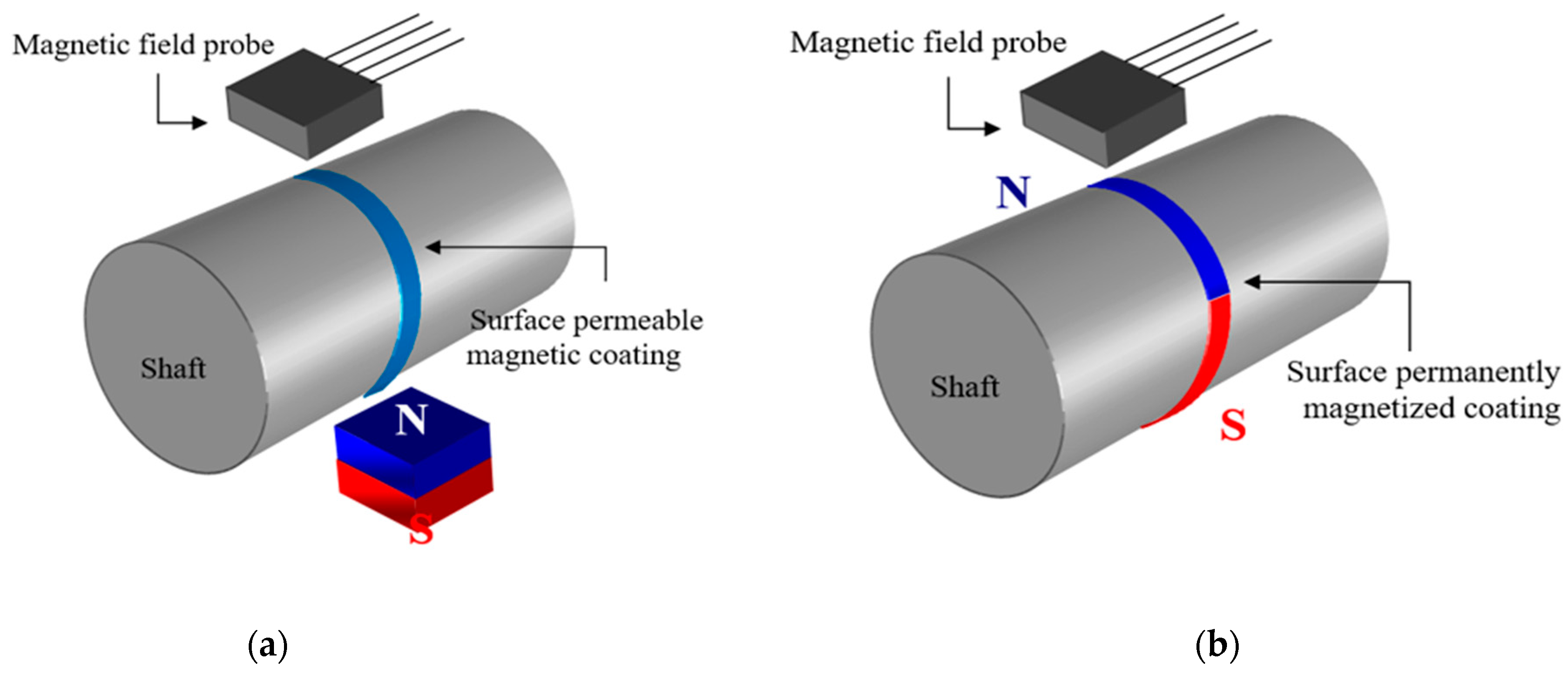
2. Magnetic Elastomer Sensor

The sensor’s operational principle is based on the change of magnetic field intensity of permanently magnetized material, due to the change of applied torque and the relative position between the magnetic field probe and material. This assembly combines in one unit three sensing principles: first for rotational relative position (angle) sensing, second for rotational speed, and third for dynamic torque sensing. Basic sensor construction is shown in Figure 2a. It consists of a special, permanently magnetized material, positioned over the drive shaft; a precise two-directional magnetic field probe; and a programmable controller unit (not shown). The controller aims to provide torque and position encoding.
The permanently magnetized material is magnetic paint, which is directly coated over the shaft. It is a low-viscosity paint composition with nano-sized ferrite particles. Magnetization orientation of the thin coating occurs during the paint drying process. After complete drying, the magnetic paint coating acts as a permanently magnetized material but with very high deformability, i.e., very low rigidity. The shaft is produced using a non-magnetic material.
The air-gap (lift-off) between magnetic field probe and shaft magnetic layer must be minimal. A two-directional anisotropic magnetoresistance (AMR) probe is used for magnetic field measurements in the sensor assembly. The sensor output signal is voltage with amplitude value up to 80 mV.
The power consumption of the sensor device is extremely low. Electric supply is required only for the magnetic field probe and for encoding the controller device.

3. Torque, Angle Position, and Rotational Speed Sensing

The proposed sensor uses the change of magnetic field intensity of the permanently magnetized material, due to the change of applied torque and relative position between the magnetic field probe and the magnetized material. The three sensing principles are combined in one unit: first for rotational relative position (angle) sensing, second for rotational speed, and third for dynamic torque sensing.

3.1. Angle Position Sensing

Rotational position is determined by measuring the field intensity change over the shaft’s magnetic coating. For each complete shaft revolution, it presents a complete sinusoidal period, i.e., 360 degrees of rotation (Figure 2b (top)). For shaft angle measurement, only the radial component of magnetic field intensity, Hr, is used. The output signal change for a complete revolution of 360° is shown in Figure 2b (top).

3.2. Rotational Speed Sensing

Rotational speed measurement is performed by counting periods of the angle position channel. For shaft angle measurement, only the radial component of the magnetic field intensity, Hr, is used. The output signal change for several revolutions is shown in Figure 2b (down).

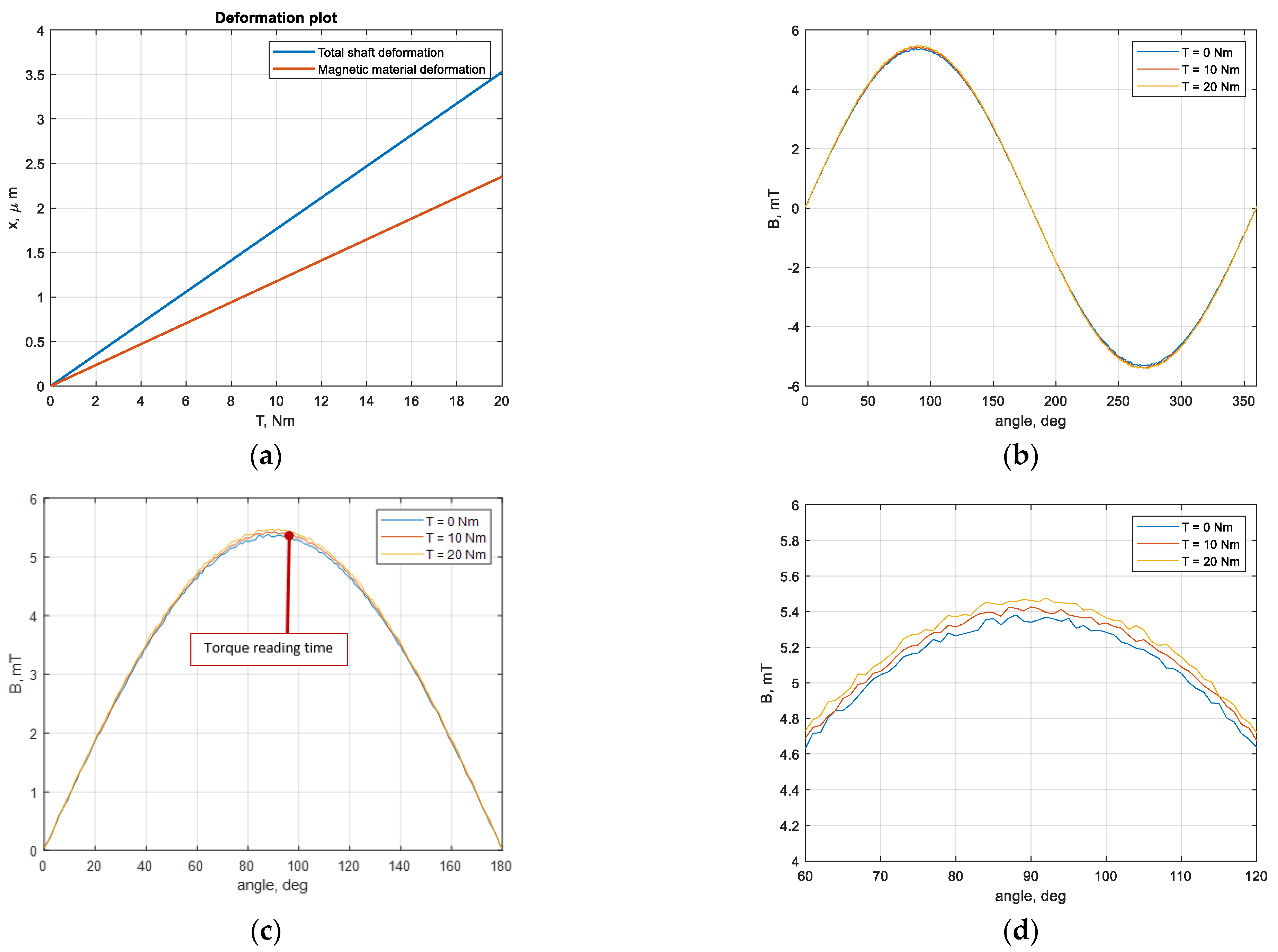
3.3. Torque Deformation Sensing

Torque sensing is performed by measuring the absolute value of the axial or circumferential component of the magnetic field intensity, produced by the permanently magnetized material. When a torque is applied over the shaft, a surface deformation appears, this affects the magnetic particle density in the coating material, which is concentrating magnetic flux density, and this in turn increases magnetic field intensity. The output signal change due to circumferential deformation is shown in Figure 2b (middle).

4. Magnetic Elastomer Material Preparation

The sensing material coating is formed by a magnetic paint over the rotational shaft surface. The magnetic paint is a low-viscosity, liquid paint composition with nano-sized ferrite particles.
The magnetic elastomer sensing material preparation as a four-step process is presented in Figure 3.
(1) selection of ferrite nano-powder particles with a certain size histogram. Pre-prepared magnetite powder is used, where the strongest particles are extracted using a permanent magnet. It is composed of oxidized barium ferrite (BaFe) BaFe12O19 nano-sized powder (BaO(Fe2O3)6). Actual TEM image of a BaFe particle cluster is shown in Figure 3(1);
(2) ferrite nano-powder particles (filler) are added to paint solution (carrier) and mixed, forming a liquid composition (10–12% wt. of filler mass). Liquid paint composition is a viscose rheological ferrofluid at this stage [25,39,47];
(3) the liquid paint composition is applied over the shaft surface using a positive stencil, forming a magnetic coating. The stencil period is 50%, but because of the liquid paint’s viscosity, the final paint coverage exceeds 65%. Magnetization patterns are presented in Figure 4;
(4) finally, coating magnetization is performed during drying with one pole pair period over the shaft’s circumference (Figure 3(4)).
By now, the coating thickness is about 100–150 μm, which gives up to 5 mT flux density for a 4 mm layer width. Three sensing patterns are employed with different application and magnetization directions (Figure 4). Magnetization patterns are circumferential (a) and align with axis of rotation (b) and 45° tilt pattern (c). The applied magnetic material strips are of 0.7 mm thickness. Actual pattern visualization is shown in Figure 4d. The painted pattern completely covers the circumference of a 20 mm diameter shaft [43,44].

5. Sensor Prototype

A basic laboratory prototype of the sensor’s active part (shaft with magnetic coating and field AMR probes) is assembled and tested. The shaft is polycarbonate polymer material with 50 MPa tensile strength. For applied torques up to 12 Nm, changes of initial magnetic field intensity of approximately 4–6% are observed due to non-uniform thickness variations.
The AMR sensor used is Philips KMZ10B. The KMZ10B is a sensitive magnetic field sensor, employing the magnetoresistive effect of thin-film permalloy. Its properties enable this sensor to be used in a wide range of applications for current and field measurement, revolution counters, angular or linear position measurement, proximity detectors, etc. KMZ10B’s field resolution is about 1 nT in the frequency range from DC to 1 MHz [51].
The KMZ10B1 magnetic field’s sensitive direction is the Y-axis according to Figure 5a. It is a single-direction sensor; so, two sensors for covering axial and circumferential directions of measurements are used. The inner circuit of the SOT–195 package is shown in Figure 5a. More detailed description of the physical principles of operation of AMR sensors can be found in [51].
The measured voltage at sensor terminals is related to the magnetic field intensity by the sensor’s output characteristic. The sensor’s output characteristic at 10 V supply voltage is shown in Figure 5b. Next, the magnetic flux density, By, is calculated by Equation (1),
B y = μ 0 H y ,
where μ0 is magnetic permeability of vacuum, μ0 = 1.25 × 10⁻⁶ H/m.
The maximal magnetic field intensity value, Hy, that can be measured accurately by the sensor is 2 kA/m, or in air the flux density, By, is 2.5 mT.

6. Sensor Numerical Modeling

A coupled numerical modeling of the magnetic elastomer sensor was performed. Two models were used, the first one is about linear deformation of the shaft under outer load torque, and the second model estimates the magnetic field change due to geometric deformation, taken from the linear mechanical model. The linear deformation model is static; the magnetic field modeling performed has both static and transient modes to estimate field effects in a given sensing position and for full shaft revolution [46,47].
Modeling interconnections are shown in Figure 6.
The magnetic elastomer sensor’s linear deformation was calculated due to mechanical stress caused by the given outer static torque. Shaft diameter is 20 mm. The axially aligned coating pattern and other design parameters completely match the other sizes of the sensor prototype. The shaft is made by polycarbonate polymer material with 50 MPa tensile strength. Applied load torques are up to 20 Nm. The linear deformation model was implemented in Ansys-Workbench. The shaft deformation and relative displacement between strips of magnetic material were acquired as the output. These data are used for magnetic field model correction and estimation of change in flux density due to the updated sensor model geometry. Coupling is one directional, because the magnetic field does not affect any mechanical quantity. The magnetic field model is implemented in Ansys-Maxwell. The sensor shaft and magnetic coating are non-electrically conductive at the considered low rotational speeds. The 3D Ansys-Maxwell solver was set to nodal-based magnetic scalar potential formulation both for static and transient modeling, because of the lack of significant electric effects.
The calculated shaft equivalent stress in applied torque range (up to 20 Nm) is within the linear deformation limit (<50 MPa). The dynamic and cyclic behavior of the shaft must be further studied and experimentally estimated.
Results for the modeled static structural deformation and strain are shown in Figure 7. Two load torque values are used, 10 Nm load torque Figure 7a,c, and 20 Nm load torque Figure 7b,d. The observed deformation is below 4 μm for the 20 Nm case and below 2 μm for the 10 Nm case. Deformation is in the linear elastic case for this polymer material as presented in Figure 8a. These values represent the total shaft deformation. For the sensor’s principle of operation, the deformation at the elastomer coating surface region is considered. These values for magnetic material deformation are also presented in Figure 8a, they are 40 % lower than the total shaft deformation.
Results for the modeled static magnetic field due to deformation are presented in Figure 9. Three rotational load cases are depicted: (a) 0 Nm, (b) 10 Nm, and (c) 20 Nm.
The equivalent magnetic flux density (√(Br + Bφ)) picked at sensor location is plotted in Figure 8b. Torque reading is made at the wave peak (Figure 8c), twice per period, zoomed signals between 60° and 120° relative angle of mechanical rotation are plotted in Figure 8d.
The output sensor signal is captured differentially compared to the no load case signal, calculated as a flux density difference by Equation (2). This is explained in much deeper detail in the next sensor testing section.
Results for the modeled static magnetic field due to deformation are presented in Figure 9. Three rotational load cases are depicted: (a) 0 Nm, (b) 10 Nm, and (c) 20 Nm. The corresponding magnetic flux density peak values are 5.336 mT, 5.387 mT, and 5.427 mT, respectively. The differentially calculated signal difference according to the torque rise, ΔT, from 0 to 20 Nm corresponds to the static flux density change of ΔB = 90 μT.

7. Sensor Prototype Testing

A sophisticated computer measurement system for static and dynamic torque testing was used (Figure 10a). The system consists of precise measurement elements as follows: reference torque sensor, reference position sensor, active electromagnetic brake as a torque load, frequency-controlled induction motor, power control unit, multifunctional multichannel data acquisition device, magnetic sensor elements of tested sensor prototype, computer control, and power supply units. The measurement system is dynamically controlled by a computer-automated control unit as a real-time application via a LabView interface. The main static and dynamic characteristics of the sensor prototype under testing are measured in a controllable environment close to real operational conditions. Mechanical and magnetic characteristics are measured and analyzed in static or and dynamic operational modes [52].
A special reference dynamic torque and rotational speed sensor CYT-302-20 is implemented in the measurement system for prototype calibration. It is a rotational strain sensor [52] with a measurement range up to 20 Nm with an average accuracy of 10 mNm and a rotational speed range of 10,000 rpm. The rotary torque sensor employs strain bridge electrical measurement technology, with a group of non-contact toroidal induction transformers to provide the power supply and a micro-power signal coupler for non-contact data transmission of signals via inductive coupling. The strain bridge supply voltage after the toroidal transformer is rectified and stabilized to avoid rotational speed influence. This voltage is used for the operational amplifier, the voltage-to-frequency (V-F) converter, and the transmitter power supply as well. The mV torque signal detected by the strain bridge is amplified, then converted to a square wave signal by the V-F converter and transmitted to a wireless external signal receiver. After being demodulated, it is converted to a real voltage value by a square waveform impulse counter. Both power supply and data acquisition are wirelessly provided, allowing the torque sensor to operate for a long time, in high-speed mode and without measurement noises, which are typical for brush connections. The torque sensor can be used both for static and for dynamic measurements. For rotational speed measurements, a code wheel is integrated with the sensor rotor. A photoelectric LED to phototransistor switch produces a pulse signal proportional to the rotational speed [52].
The testing process is focused mainly on the torque sensing ability and rotational speed. A small eccentricity or axis deviation can change signal characteristics at the sensor output. In the proposed experiment, lift-off between the coating and the AMR pickup sensor is eliminated and the field sensor is touching the coating. Another observed problem is the change of initial magnetic field intensity of approximately 4–6% due to non-uniform magnetic paint thickness variations during drying. We believe that these imperfections of particular design realization cause some of the nonlinearities of measured output characteristics. The vibration of the shaft at high rotational speeds is also an issue that must be addressed in future research activities on signal–noise spectrum sources’ determination.
The measured flux density, Bm, over the magnetic sensing element is expressed as Equation (2).
B m = B 0 + d B ,
where B0 is the existing magnetic field from the sensing element, measurement setup, and environment reluctance fields, and the magnetization, dB, is the magnetic flux density change caused by the sensing material’s deformation.
Torques in the range from 0 to 12 Nm are applied over the sensing shaft. The output characteristics for the three tested sensing patterns are shown in Figure 11 and Table 1.
Output characteristics are fitted with the linear interpolation polynomic Equation (3), unit dimensions of coefficients and calculated numerical values are summarized in Table 1.
d B [ μ T ] = a [ μ T / N m ] T [ N m ] + b [ μ T ] .
Circumferential and axially aligned patterns present very similar results with good linearity of the output characteristic. The sensing ratio is 5 µT/Nm ± 2% rms uncertainty. The 45° tilt pattern shows reduced sensitivity below 2.75 µT/Nm with increased uncertainty of 4% rms according to increased non-linearity.
Differentially calculated signal difference from FEM modeling of the main sensor pattern, which was presented in Section 4, shows that, for ΔT, from 0 to 20 Nm ΔB = 90 μT, or a total sensitivity of 4.55 µT/Nm.
These measurements (Figure 12b) are for static load torques applied. Dynamic response in range from 0 to 3000 rpm range tested (Figure 12a) requires frequency dependent corrections to keep sensing ratio linearity and reduce magnetic inductive effects.
Figure 12a shows the tested sensor output (Test) at constant static torque (0 rpm) and dynamic load torque (up to 3000 rpm), with constant reference torque (Ref.) of 8 ± 0.1 Nm. We do not consider these differences as a measuring uncertainty at the moment, this is an output characteristic that needs a frequency-dependent compensation of output signal. Without rotational frequency compensation, the 5% uncertainty limit is lost after 300 rpm range.
It must be pointed that magnetic elastomer materials tend to undergo irreversible plastic deformation and cause a drift of indications in long-term usage. All obvious benefits of elastomer sensing technologies are confronted with non-linear polymer properties, material aging processes, and property degradation [53]. The authors believe that constructive polymers and printed magnetic devices will have an important meeting point for the research and development of many new devices with a shorter operational life.

8. Conclusions

The proposed torque sensor design with magnetic elastomer material has a linear output characteristic with a 5% uncertainty limit for the 12 Nm range. The estimated total static sensitivity is 4.55 µT/Nm. Sensor uncertainty is mainly influenced by variations in the magnetic coating thickness and magnetic sensor lift-off changes. These imperfections must be reduced for better sensitivity in static and dynamic operational mode.
Interaction between AMR/GMR sensor magnetic properties and the magnetic elastomer coating field must be modeled to estimate the appearance of some additional reluctance. The dynamic delay of the AMR circuit must be estimated in the total response time calculation. Rotational-frequency-dependent compensation of output signal is needed for sensor dynamic usage after 300 rpm for this particular design’s implementation.
Other difficulties to overcome concern reluctance magnetic fields existing in electromagnetic propulsion devices. Additionally, significant vibrations could cause resonant deformations in the sensing material and reduce the dynamic overall device sensitivity.
Sensor design and performance should be optimized for better sensitivity. Temperature and vibration effects over the sensor performance should be experimentally tested. The operational life of unprotected polymer coatings is also an open issue, as magnetic material properties of such paints are susceptible to aging.
Despite these difficulties, simple and reliable construction, contactless operation, low energy consumption, and overload capability make these sensors of great importance for next-generation mechatronic systems for robotics, industrial automation, transportation, power conversion, additive manufacturing, healthcare, and many more beyond.

Author Contributions

Conceptualization, I.M. and V.M.; methodology, V.M. and I.M.; validation, V.M.; formal analysis, I.M. and V.M.; investigation, V.M.; resources, I.M.; data curation, V.M.; writing—original draft preparation, V.M. and I.M.; writing—review and editing, I.M. and V.M.; visualization, V.M.; supervision, I.M.; project administration, I.M.; funding acquisition, I.M. All authors have read and agreed to the published version of the manuscript.

Funding

This work was partially supported by the National Science Fund of the Bulgarian Ministry of Education and Science, project no. DN17/5 “Mechatronic magneto-mechanical transmission systems”.

Data Availability Statement

Not applicable.

Conflicts of Interest

The authors declare no conflict of interest.

References

  1. Chen, C.; Lin, T.C.; Lin, T.; Lin, P. Design of a motor bracket multi-axis force/torque sensor. In Proceedings of the 13th International Conference on Ubiquitous Robots and Ambient Intelligence (URAI), Xi’an, China, 19–22 August 2016; pp. 305–307. [Google Scholar]
  2. Myers, D.R.; Pisano, A.P. Torque measurements of an automotive halfshaft utilizing a MEMS resonant strain gauge. In Proceedings of the TRANSDUCERS 2009 International Solid-State Sensors, Actuators and Microsystems Conference, Denver, CO, USA, 21–25 June 2009; pp. 1726–1729. [Google Scholar]
  3. Kim, I.; Kim, H.; Song, J. Design of joint torque sensor and joint structure of a robot arm to minimize crosstalk and torque ripple. In Proceedings of the 9th International Conference on Ubiquitous Robots and Ambient Intelligence (URAI), Daejeon, Korea, 26–28 November 2012; pp. 404–407. [Google Scholar]
  4. Park, C.; Kyung, J.H.; Choi, T.; Do, H.M.; Park, D.; Kim, B. Study on the requirements of joint torque sensors considering mechanical condition of the joint mechanism of a manipulator. In Proceedings of the 12th International Conference on Control, Automation and Systems, JeJu Island, Korea, 17–21 October 2012; pp. 2114–2116. [Google Scholar]
  5. Sandakalum, T.; Suraji, S.; Weerasekara, I.; Lalitharatne, T.; Chathuranga, D. Design and Characterization of a 1-axis Compact Torque Sensor for a Collaborative Robot Arm. In Proceedings of the IEEE International Conference on Information and Automation for Sustainability (ICIAfS), Colombo, Sri Lanka, 21–22 December 2018; pp. 1–6. [Google Scholar]
  6. Kim, D.; Kim, B.; Hwang, J.; Kim, E. The new 2 DoF frame torque sensor for the Metacarpophalangeal joint in robotic hand. In Proceedings of the 8th International Conference on Ubiquitous Robots and Ambient Intelligence (URAI), Incheon, Korea, 23–26 November 2011; pp. 556–559. [Google Scholar]
  7. Shvetsov, A.; Zhgoon, S.; Lonsdale, A.; Sandacci, S. Deformation sensitive cuts of quartz for torque sensor. In Proceedings of the IEEE International Ultrasonics Symposium, San Diego, CA, USA, 11–14 October 2010; pp. 1250–1253. [Google Scholar]
  8. Zi, X.; Zhao, S.; Geng, S.; Wu, L.; Pang, H. A Wireless Torque Sensor Based on Surface Acoustic Wave. In Proceedings of the International Conference on Wireless Communication and Sensor Network, Wuhan, China, 13–14 December 2014; pp. 326–329. [Google Scholar]
  9. Muro, H.; Saito, C.; Shimada, M.; Furuya, Y. Magnetostrictive-ring type torque sensor using two Hall ICs with differential magnetic field detection. In Proceedings of the IEEE Sensors, Valencia, Spain, 2–5 November 2014; pp. 412–415. [Google Scholar]
  10. Wang, Y.; Jang, W.; Huang, C. Lightweight Torque Sensor Based on a Gradient Grating Period Guided-Mode Resonance Filter. IEEE Sens. J. 2019, 19, 6610–6617. [Google Scholar] [CrossRef]
  11. Hoehn, K.; Olsson, A.; Arkwright, J.W. High Capacity Torque and Compression Measurements Using Fibre Optic Sensors. In Proceedings of the 2nd International Conference for Fibre-optic and Photonic Sensors for Industrial and Safety Applications (OFSIS), Brisbane, QLD, Australia, 8–10 January 2017; pp. 39–44. [Google Scholar]
  12. Leal-Junior, A.G.; Theodosiou, A.; Min, R.; Casas, J.; Díaz, C.R.; Dos Santos, W.M.; Pontes, M.J.; Siqueira, A.A.; Marques, C.; Kalli, K.; et al. Quasi-Distributed Torque and Displacement Sensing on a Series Elastic Actuator’s Spring Using FBG Arrays Inscribed in CYTOP Fibers. IEEE Sens. J. 2019, 19, 4054–4061. [Google Scholar] [CrossRef]
  13. Watanabe, K.; Hara, K.; Toyama, S. Novel Sheet-Type Torque Sensor Using Electrolyte. In Proceedings of the IEEE Sensors, Montreal, QC, Canada, 27–30 October 2019; pp. 1–4. [Google Scholar]
  14. Hein, M.; Park, J.; Cozzo, J.A.; Flatau, A.; Stadler, B.J.H. Electrodeposited Fe–Ga Alloy Films for Directly Coupled Noncontact Torque Sensing. IEEE Sens. J. 2019, 19, 6655–6661. [Google Scholar] [CrossRef]
  15. Arionfard, H.; Ramezani, H. Measuring Absolute Rotation and Torque in Series Elastic Actuators with a Single Sensor. IEEE Sens. J. 2020, 20, 14685–14693. [Google Scholar] [CrossRef]
  16. Flieh, H.M.; Totoki, E.; Lorenz, R.D. Dynamic Shaft Torque Observer Structure Enabling Accurate Dynamometer Transient Loss Measurements. IEEE Trans. Ind. Appl. 2018, 54, 6121–6132. [Google Scholar] [CrossRef]
  17. Al-Mai, O.; Ahmadi, M.; Albert, J. Design, Development and Calibration of a Lightweight, Compliant Six-Axis Optical Force/Torque Sensor. IEEE Sens. J. 2018, 18, 7005–7014. [Google Scholar] [CrossRef]
  18. Jiang, K.; Zhou, Y.; Han, L.; Li, L.; Liu, Y.; Hu, S. Design of a High-Resolution Instantaneous Torque Sensor Based on the Double-Eccentric Modulation Principle. IEEE Sens. J. 2019, 19, 6595–6601. [Google Scholar] [CrossRef]
  19. Ji, X.; Fan, Y.; Chen, J.; Han, T.; Cai, P. Passive Wireless Torque Sensor Based on Surface Transverse Wave. IEEE Sens. J. 2016, 16, 888–894. [Google Scholar] [CrossRef]
  20. Cao, K.; Deng, Y. Design and analysis of an automotive vibration reduction system based on magneto-rheological elastomer. In Proceedings of the International Conference on Mechatronics and Automation, Changchun, China, 9–12 August 2009; pp. 1645–1649. [Google Scholar]
  21. Ausanioa, G.; Iannottia, V.; Ricciardib, E.; Lanottec, L.; Lanotte, L. Magneto-piezoresistance in Magnetorheological elastomers for magnetic induction gradient or position sensors. Sens. Actuators A Phys. 2014, 205, 235–239. [Google Scholar] [CrossRef] [Green Version]
  22. Li, R.; Zhou, M.; Wang, M.; Chen, S.; Yang, P. The Influence of Force and Magnetic Field on the Self-Sensing Characteristics of Magneto-Rheological Elastomer Bearing. In Proceedings of the Prognostics and System Health Management Conference (PHM-Chongqing), Chongqing, China, 26–28 October 2018; pp. 758–763. [Google Scholar]
  23. Zhu, X.; Liu, L.; Guo, H.; Xu, Z.; Hou, W.; Niu, L. Modeling and Analysis of an Electromagnetic Fully Variable Valve Train with a Magnetorheological Buffer. Electronics 2019, 8, 996. [Google Scholar] [CrossRef] [Green Version]
  24. Ralchev, M.; Mateev, V.; Marinova, I. 3D Printing of Magnetic Materials by FFF Technology. In Proceedings of the 2020 12th Electrical Engineering Faculty Conference (BulEF), Varna, Bulgaria, 9–12 September 2020; pp. 1–4. [Google Scholar]
  25. Mateev, V.; Marinova, I.; Saito, Y. Coupled Field Modeling of Ferrofluid Heating in Tumor Tissue. IEEE Trans. Magn. 2013, 49, 1793–1796. [Google Scholar] [CrossRef]
  26. Arslan Hafeez, M.; Usman, M.; Umer, M.A.; Hanif, A. Recent Progress in Isotropic Magnetorheological Elastomers and Their Properties: A Review. Polymers 2020, 12, 3023. [Google Scholar] [CrossRef]
  27. Muhazeli, N.S.; Nordin, N.A.; Ubaidillah, U.; Mazlan, S.A.; Abdul Aziz, S.A.; Nazmi, N.; Yahya, I. Magnetic and Tunable Sound Absorption Properties of an In-Situ Prepared Magnetorheological Foam. Materials 2020, 13, 5637. [Google Scholar] [CrossRef] [PubMed]
  28. Jamari, S.K.M.; Nordin, N.A.; Aziz, S.A.A.; Nazmi, N.; Mazlan, S.A. Systematic Review on the Effects, Roles and Methods of Magnetic Particle Coatings in Magnetorheological Materials. Materials 2020, 13, 5317. [Google Scholar] [CrossRef] [PubMed]
  29. Dohmen, E.; Kraus, B. Coupled Anisotropic Magneto-Mechanical Material Model for Structured Magnetoactive Materials. Polymers 2020, 12, 2710. [Google Scholar] [CrossRef]
  30. Bica, I.; Anitas, E.M.; Chirigiu, L. Hybrid Magnetorheological Composites for Electric and Magnetic Field Sensors and Transducers. Nanomaterials 2020, 10, 2060. [Google Scholar] [CrossRef]
  31. Kang, S.S.; Choi, K.; Nam, J.-D.; Choi, H.J. Magnetorheological Elastomers: Fabrication, Characteristics, and Applications. Materials 2020, 13, 4597. [Google Scholar] [CrossRef]
  32. Kwon, S.H.; Lee, J.H.; Choi, H.J. Magnetic Particle Filled Elastomeric Hybrid Composites and Their Magnetorheological Response. Materials 2018, 11, 1040. [Google Scholar] [CrossRef] [Green Version]
  33. Samal, S.; Škodová, M.; Abate, L.; Blanco, I. Magneto-Rheological Elastomer Composites: A Review. Appl. Sci. 2020, 10, 4899. [Google Scholar] [CrossRef]
  34. Yoon, J.-Y.; Hong, S.-W.; Park, Y.-J.; Kim, S.-H.; Kim, G.-W.; Choi, S.-B. Tunable Young’s Moduli of Soft Composites Fabricated from Magnetorheological Materials Containing Microsized Iron Particles. Materials 2020, 13, 3378. [Google Scholar] [CrossRef]
  35. Elías-Zúñiga, A.; Palacios-Pineda, L.M.; Perales-Martínez, I.A.; Martínez-Romero, O.; Olvera-Trejo, D.; Jiménez-Cedeño, I.H. Investigating the Mullins Effect and Energy Dissipation in Magnetorheological Polyurethane Elastomers. Int. J. Mol. Sci. 2020, 21, 5318. [Google Scholar] [CrossRef] [PubMed]
  36. Jeong, U.-C. Application of Adaptive Tuned Magneto-Rheological Elastomer for Vibration Reduction of a Plate by a Variable-Unbalance Excitation. Appl. Sci. 2020, 10, 3934. [Google Scholar] [CrossRef]
  37. Asadi Khanouki, M.; Sedaghati, R.; Hemmatian, M. Multidisciplinary Design Optimization of a Novel Sandwich Beam-Based Adaptive Tuned Vibration Absorber Featuring Magnetorheological Elastomer. Materials 2020, 13, 2261. [Google Scholar] [CrossRef] [PubMed]
  38. Zainudin, A.A.; Yunus, N.A.; Mazlan, S.A.; Shabdin, M.K.; Abdul Aziz, S.A.; Nordin, N.A.; Nazmi, N.; Abdul Rahman, M.A. Rheological and Resistance Properties of Magnetorheological Elastomer with Cobalt for Sensor Application. Appl. Sci. 2020, 10, 1638. [Google Scholar] [CrossRef] [Green Version]
  39. Song, B.-K.; Yoon, J.-Y.; Hong, S.-W.; Choi, S.-B. Field-Dependent Stiffness of a Soft Structure Fabricated from Magnetic-Responsive Materials: Magnetorheological Elastomer and Fluid. Materials 2020, 13, 953. [Google Scholar] [CrossRef] [Green Version]
  40. Jones, D.; Wang, L.; Ghanbari, A.; Vardakastani, V.; Kedgley, A.E.; Gardiner, M.D.; Vincent, T.L.; Culmer, P.R.; Alazmani, A. Design and Evaluation of Magnetic Hall Effect Tactile Sensors for Use in Sensorized Splints. Sensors 2020, 20, 1123. [Google Scholar] [CrossRef] [Green Version]
  41. Kukla, M.; Warguła, Ł.; Talaśka, K.; Wojtkowiak, D. Magnetorheological Elastomer Stress Relaxation Behaviour during Compression: Experiment and Modelling. Materials 2020, 13, 4795. [Google Scholar] [CrossRef]
  42. Qiao, Y.; Zhang, J.; Zhang, M.; Liu, L.; Zhai, P. A Magneto-Hyperelastic Model for Silicone Rubber-Based Isotropic Magnetorheological Elastomer under Quasi-Static Compressive Loading. Polymers 2020, 12, 2435. [Google Scholar] [CrossRef]
  43. Mateev, V.; Marinova, I. Magnetic Elastomer Sensor for Dynamic Torque Measurements in Magnetic Gears. In Proceedings of the 13th International Conference on Sensing Technology (ICST), Sydney, Australia, 2–4 December 2019; pp. 1–4. [Google Scholar]
  44. Mateev, V.; Marinova, I. Magnetic Elastomer Sensor for Dynamic Torque. In Proceedings of the 19th International Symposium on Electromagnetic Fields in Mechatronics, Electrical and Electronic Engineering (ISEF), Nancy, France, 29–31 August 2019; pp. 1–2. [Google Scholar]
  45. Yoo, B.; Na, S.; Flatau, A.B.; Pines, D.J. Evaluation of Magnetorheological Elastomers with Oriented Fe–Ga Alloy Flakes for Force Sensing Applications. IEEE Trans. Magn. 2016, 52, 1–4. [Google Scholar] [CrossRef]
  46. Murao, S.; Hirata, K.; Miyasaka, F. Analysis of Variable Stiffness Magnetorheological Elastomer Employing Particle Method and FEM. IEEE Trans. Magn. 2016, 52, 1–4. [Google Scholar] [CrossRef]
  47. Marinova, I.; Mateev, V. Thermo-Electro-Magnetic Convection in Electrically Conductive Ferrofluids. In Proceedings of the 22nd International Conference on the Computation of Electromagnetic Fields (COMPUMAG), Paris, France, 15–19 July 2019; pp. 1–4. [Google Scholar]
  48. Lacheisserie, T. Magnetostriction Theory and Applications of Magnetoelasticity; CRC Press, Inc.: Boca Raton, FL, USA, 1993. [Google Scholar]
  49. Li, R.C.; Cabrera, C.; Moron, A.; Garcia, A.; González, M. Magnetic Sensors Based on Amorphous Ferromagnetic Materials: A Review. Sensors 2015, 15, 28340–28366. [Google Scholar]
  50. Petrov, R.V.; Bichurin, M.I.; Leontiev, V.S.; Kolesnikov, N.A.; Milenov, I.K.; Bozhkov, S.T.; Stanev, L.G.; Pacheliev, V.T.; Bozhkov, P.T. The crankshaft position sensor based on magnetoelectric materials. In Proceedings of the IEEE International Power Electronics and Motion Control Conference (PEMC), Varna, Bulgaria, 25–28 September 2016; pp. 848–853. [Google Scholar]
  51. Philips Semiconductors. Magnetic Field Sensors—General; Philips Semiconductors. Available online: https://www.mikrocontroller.net/attachment/33100/SC17_GENERAL_MAG_98_1.pdf (accessed on 25 January 2021).
  52. Mateev, V.; Marinova, I. Loss estimation of magnetic gears. Electr. Eng. 2020, 102, 387–399. [Google Scholar] [CrossRef]
  53. Aziz, S.A.A.; Mazlan, S.A.; Ubaidillah, U.; Mohamad, N.; Choi, S.-B.; Che Aziz, M.A.; Johari, M.A.F.; Homma, K. Thermal Aging Rheological Behavior of Magnetorheological Elastomers Based on Silicone Rubber. Int. J. Mol. Sci. 2020, 21, 9007. [Google Scholar] [CrossRef] [PubMed]
Figure 1. Magnetic elastomer deformation sensor types. Outer magnetic field source with a surface permeable coating (a), and permanently magnetized elastomer coating over the shaft surface (b).
Electronics 10 00309 g001
Figure 2. Magnetic torque and angle sensor: (a) the device’s principle of operation and (b) variations of magnetic field intensity vector components (Hr, Hφ) of the rotational angle position, φ, and the shaft deformation due to mechanical torque, T.
Electronics 10 00309 g002
Figure 3. Magnetic elastomer sensing material preparation as a four-step process: (1) selection of ferrite particles with a certain size histogram; (2) liquid paint composition mixing; (3) coating application over shaft surface using a positive stencil; (4) finally, the single pole pair magnetization during drying.
Electronics 10 00309 g003
Figure 4. Magnetization patterns: (a) circumferential; (b) aligned with axis of rotation; (c) 45° tilt pattern; and (d) realized over test prototype magnetic paint magnetization pattern.
Electronics 10 00309 g004
Figure 5. Sensor KMZ10B: (a) package wiring diagram; (b) sensor output voltage characteristic.
Electronics 10 00309 g005
Figure 6. Modeling interconnections. Calculated mechanical deformation and displacement are used for magnetic field modeling in static and transient modes.
Electronics 10 00309 g006
Figure 7. Static structural deformation (a,b) and strain (c,d) for two different load torque cases. 10 Nm load torque (a,c). 20 Nm load torque (b,d).
Electronics 10 00309 g007
Figure 8. Elastomer sensor model magnetic flux densities, captured at magnetic sensor location. Torque to mechanical deformation characteristics (a); magnetic flux density variation for one complete revolution (b); modeled magnetic flux density variation for half rotation and three different torque loads 0, 10, and 20 Nm (c); zoomed magnetic flux density output signal between 60° and 120° relative angle of mechanical rotation (d).
Electronics 10 00309 g008
Figure 9. Magnetic elastomer sensor static magnetic field results due to torque deformation, three rotational load cases are depicted 0 Nm (a), 10 Nm (b), and 20 Nm (c).
Electronics 10 00309 g009
Figure 10. Computer-aided testing system for static and dynamic torque measurement, general view (a), functional block scheme (b).
Electronics 10 00309 g010
Figure 11. Flux density output characteristics in three tested patterns: (a) output characteristics, torque to magnetic flux density change; (b) linear interpolations of output characteristics.
Electronics 10 00309 g011
Figure 12. Flux density output characteristics from rotational speed up to 3000 rpm (a), comparison of reference sensor (Ref.) and tested sensor (Test) readings for two torques 12 and 8 Nm, red lines represent the uncertainty limits (b).
Electronics 10 00309 g012
Table 1. Linear interpolation polynomic coefficients for three studied cases.
Pattern TypePolynomic Interpolation CoefficientsMinimization Uncertainty Rms
Circumferential (0°)a = 5.00 [μT/Nm]| b = 2.0 [μT]1.87%
Align with axis of rotation (90°)a = 4.85 [μT/Nm]| b = 2.1 [μT]2.15%
Tilt pattern (45°)a = 2.75 [μT/Nm]| b = 3.1 [μT]3.22%
Publisher’s Note: MDPI stays neutral with regard to jurisdictional claims in published maps and institutional affiliations.

