Article

Automatic Code Generation of Safety Mechanisms in Model-Driven Development

Institute of Computer Science, University of Osnabrück, Wachsbleiche 27, 49090 Osnabrück, Germany
*
Author to whom correspondence should be addressed.
Electronics 2021, 10(24), 3150; https://doi.org/10.3390/electronics10243150
Submission received: 15 October 2021 / Revised: 7 December 2021 / Accepted: 13 December 2021 / Published: 17 December 2021
(This article belongs to the Special Issue Software Verification and Validation for Embedded Systems—Volume 2)

Abstract

:
In order to meet regulatory standards in the domain of safety-critical systems, these systems have to include a set of safety mechanisms depending on the Safety Integrity Level (SIL). This article proposes an approach for how such safety mechanisms may be generated automatically via Model-Driven Development (MDD), thereby improving developer productivity and decreasing the number of bugs that occur during manual implementation. The approach provides a structured way to define safety requirements, which may be parsed automatically and are used for the generation of software-implemented safety mechanisms, as well as the initial configuration of hardware-implemented safety mechanisms. The approach for software-implemented safety mechanisms relies on the Unified Modeling Language (UML) for representing these mechanisms in the model and uses model transformations to realize them in an intermediate model, from which code may be generated with simple 1:1 mappings. The approach for hardware-implemented safety mechanisms builds upon a template-based code snippet repository and a graphical user interface for configuration. The approach is applied to the development of a safety-critical fire detection application and the runtime of the model transformations is evaluated, indicating a linear scalability of the transformation steps. Furthermore, we evaluate the runtime and memory overhead of the generated code.

1. Introduction

The failure of safety-critical systems may harm humans or the environment [1]. Examples of this are the recent crashes of two Boeing 737 MAX 8 in 2018 and 2019, leading to the loss of life of everyone on board. The reason for both crashes has been traced back to the erroneous activation of a software module [2]. More examples may be found in [3]. As the failure of a safety-critical system has such serious consequences, strict regulations for the market admission of such systems exist. These regulations often include the need for conformance with a relevant safety standard for the safety-critical system. There exist domain-specific standards, e.g., [4] for the medicinal domain, [5] for airborne systems or [6] for the automotive domain. There also exist domain-independent safety standards, e.g., [7], which applies to general electrical/electronic/programmable electronic systems. These safety standards recommend a set of safety mechanisms that a product has to contain to claim conformance with the respective standard. This article proposes an approach for the automatic code generation of such safety mechanisms by using Model-Driven Development (MDD) techniques.
The proposed approach offers a plugin for MDD tools that assists developers in refining a set of high-level safety requirements into derived requirements ( R D ). The requirements ( R D ) specify which safety mechanisms should be applied to which application element. These derived requirements are subject to a set of automated model transformations that generate the specified safety mechanisms in the model. The generation process distinguishes between software-implemented and hardware-implemented safety mechanisms.
For software-implemented safety mechanisms, the generation process automatically annotates a class diagram in the Unified Modeling Language (UML) with a set of safety stereotypes based on the derived safety requirements R D . Subsequently, an intermediate model is created via model transformations. These model transformations add classes that realize the specified safety mechanisms. Furthermore, the stereotyped model elements are automatically transformed to interact with these generated classes. The intermediate model contains enough information that the code generated from this model, e.g., by common MDD tools [8,9], contains the realized safety mechanisms.
For hardware-implemented safety mechanisms, we utilize a GUI tool [10] that allows developers to configure the employed pins for hardware interfaces, e.g., for General Purpose Input/Output (GPIO) or Universal Asynchronous Receiver Transmitter (UART). Moreover, the properties of the hardware interfaces may be configured, e.g., whether the UART should use a parity bit. The properties may be automatically inferred from the derived requirements R D . The configuration within this GUI is subsequently used as the input for a template-based code generation process. This process utilizes code snippet repositories to generate the source code that realizes this configuration for a given microcontroller.
The aforementioned research results provide the following contributions:
  • An integration of safety mechanisms within the application model. This supports the development of safety-critical systems by offering features like semi-formal methods (UML) and automatic code generation (the MDD generation process). Both semi-formal methods and automatic code generation are highly recommended by the safety standard IEC 61508 [7]. Thus, our approach helps developers to comply with this safety standard and others derived from IEC 61508, e.g., ISO26262 [6].
  • The automation of a manual activity, i.e., the implementation of safety mechanisms in safety-critical systems. Such automation may improve developer productivity and reduce the number of bugs in the implementation [11,12].
  • Due to the automatic generation of the safety mechanisms, developers require less knowledge about their implementation details. This is important because knowledge about safety is only a very minor topic in current computer science and software engineering curricula [13,14]. Automating the implementation of safety mechanisms means fewer opportunities for developers to make implementation mistakes due to insufficient knowledge in the safety domain. Thus, our approach may contribute to improving the overall safety of the system.
This article builds upon previous work [15,16,17,18,19]. It integrates these standalone approaches into a novel holistic framework for the automatic generation of safety mechanisms. The framework also incorporates a novel generation approach for automated error handling during the application’s runtime. Moreover, we show how the framework may be extended to provide code generation for other safety mechanisms. Another novelty to [15,16,17,18,19] is the combination of this approach with requirements engineering, thereby enabling the generation of safety mechanisms directly from a set of structured safety requirements. Furthermore, we provide a novel evaluation of the code-level efficiency of the safety mechanisms proposed in [15,16,17,18,19], which have been modified due to the integration with the framework proposed in this article.
The remainder of this article is organized as follows: Section 2 presents background on model-driven code generation and the terminology used in this article. Section 3 presents related research, while Section 4 presents the workflow of our approach, as well as an application example. Section 5 describes how high-level safety requirements may be derived into requirements that enable the automatic code generation of safety mechanisms. Section 6 and Section 7 describe the generation process for software-implemented and hardware-implemented safety mechanisms. Section 8 evaluates the scalability of the proposed approach by measuring the runtime of the different model transformation steps, as well as studying the efficiency of the generated code on a target platform. Section 9 concludes this article.

2. Background

This section presents how safety mechanisms, whose automatic generation is a key point of this article, are relevant in the development of safety-critical systems. Furthermore, a brief summary of the code generation from UML models is given.

2.1. Safety Mechanisms

In order to ensure that safety-critical systems actually operate in a safe manner, various domain-specific safety standards exist, e.g., [4,6]. They are often derived from IEC 61508 [7], a domain-independent safety standard. IEC 61508 uses the concept of Safety Integrity Levels (SILs). SILs refer to the probability that a system will perform in a safe manner according to its specification under all stated conditions. There exist four different SILs and IEC 61508 offers recommendations as to how the required probabilities may be achieved. One type of recommendation is the use of safety mechanisms. These are non-functional system elements whose aim is to ensure the correct operation of the system in the presence of faults and/or errors. As these safety mechanisms are a recurrent occurrence in safety-critical systems, their automatic generation may reduce the development time of such systems.
This article uses several safety mechanisms that focus on the protection of member variables of objects (also referred to as attributes in the context of UML). These include:
  • The calculation of a Cycling Redundancy Checksum (CRC) for the attribute when it is accessed and which is checked when the attribute is modified (CRC check).
  • The triplication of the attribute and a comparison of whether these replicas are the same when the attribute is accessed, i.e., Triple Modular Redundancy (TMR).
  • A numeric range check that is performed when the attribute is accessed (Range check).
  • A time-based check that determines whether an attribute that is accessed has been modified within a certain time frame (Update check).
Furthermore, this article uses three different types of timing constraint monitoring. These are mechanisms executed at runtime which monitor whether an operation finishes within a certain time frame. One of these mechanisms is deadline supervision, i.e. a sequential check that is performed once the monitored operation is finished. The other two mechanisms are watchdog-based approaches that are capable of detecting the violation of a timing constraint as soon as it occurs. The two watchdog variants differ in their methodology. One uses an approach based on (software) concurrency, while the other operates via hardware timers and interrupts.
The last group of safety mechanisms used within this article is voting. In voting, multiple, redundant inputs are compared with each other with the intent of obtaining a reliable estimate of the ground truth. There exist different types of voting, e.g., majority voting, plurality voting, as well as the calculation of the median and the arithmetic mean.

2.2. Terminology: Software- and Hardware-Implemented Safety Mechanisms

This article uses the terms software-implemented safety mechanisms and hardware-implemented safety mechanisms to refer to the way in which a safety mechanism is realized. A software-implemented safety mechanism is realized entirely in software, while a hardware-implemented safety mechanism is predominantly realized in hardware and may be additionally configured via software. Note that this distinction does not make a statement about the type of errors that may be detected by each safety mechanism. For example, a software-implemented safety mechanism may monitor the output of a sensor to infer a hardware fault within the sensor.
The generation of software-implemented safety mechanisms refers to the actual generation of the source code for these mechanisms via MDD. For hardware-implemented safety mechanisms, the presented code generation approach is limited to generating the source code for configuring the specific hardware, e.g., configuring a UART to use error-detecting codes. The manufacturing of this hardware, or its description in a hardware description language, e.g., VHDL, is outside the scope of this article. This limitation in scope is not an issue from the perspective of a software developer, as the respective hardware is part of commercial off-the-shelf microcontrollers. In the context of hardware-implemented safety mechanisms, we use the term hardware interface to refer to microcontroller peripherals, e.g., GPIOs or UARTs.

2.3. Automatic Code Generation from UML Models

MDD tools, e.g., IBM Rhapsody [8] or Papyrus [9], are able to model UML diagrams and generate code from them. In the case of class diagrams, many tools are capable of generating skeleton code for the modeled classes, i.e., the class and method declarations without their implementation. Some tools, e.g., Rhapsody and Papyrus, also provide the capability of providing method implementations within the model via submenus. These method implementations are copy-pasted inside the respective methods during the code generation process. Thus, these MDD tools allow developers to generate the entire source code of the application from the model. This article assumes that an MDD tool capable of the aforementioned features is used to develop the application. The prototype implementation of the presented approach is realized for the specific MDD tool IBM Rhapsody [8]. However, it does not use any other features as those listed above, besides the additional capability to modify the model via an API or a model transformation language such as the Atlas Transformation Language (ATL) [20]. Thus, the approach may be easily implemented for other MDD tools as well.

3. Related Work

Several research approaches propose the automatic generation of error detection mechanisms. However, they either do not consider the integration in an MDD context [21], or they depend on domain-specific modeling languages instead of building atop a wide-spread, standardized modeling language, such as UML [22,23]. This makes their integration into a wide variety of MDD tools more difficult, as these often only support UML. Our approach, in contrast, is entirely specified in UML at the modeling level. Another category of approaches enables the model-driven generation of structural model elements that represent safety features [24]. However, they depend on manual refinements of the model to produce the dynamic behavior of the safety mechanism. Thus, this approach is only semi-automatic.
Another approach proposes the model-based generation of runtime checks in general, i.e., the approach is not specifically intended for the development of safety-critical systems [25]. Once more, this approach designs its own domain-specific language instead of building on top of UML. There are also some approaches that aim to verify structural constraints during runtime, for example, class and component relationships [26,27,28]. Our approach, on the other hand, targets dynamic behavior during runtime. Such dynamic behavior is also the focus of assertion- and contract-based techniques [29,30]. Assertion- and contract-based techniques are a form of runtime check that are directly specified in the source code. Thus they do not provide any model representation. Furthermore, a specific contract or assertion is not reusable in other applications [25].
Several other approaches combine selected safety aspects with MDD [31,32,33,34]. However, they target other phases of the development lifecycle rather than the actual realization step of the system which is the focus of our approach. As these phases are primarily located prior to the realization step, their approaches may be used in a complementary fashion to ours.
There are also some commercial approaches that aim to increase the safety of the underlying operating systems [35,36]. Our approach, in contrast, focuses on the application level. There also exist some completed research projects that target an increase in safety in general. The EU project SafeAdapt [37] provides a model-driven approach for self-adaption in safety-critical systems in the context of the automotive sector [38,39,40]. While our work focuses on the automatic generation of error detection mechanisms, theirs is more focused on achieving a safe state of the system after an error has occurred. As error handling and error detection are related, the two approaches might be integrated with each other. Another EU project targeting safety in cyber-physical systems of mixed-criticality is SAFURE [41]. While our approaches focus on the application level, their work is more concerned with the safety of the underlying system. For example, they focus on improving the predictability and timing analysis of networks that connect individual microcontrollers inside cyber-physical systems [42,43,44], as well as timing issues related to the use of multicore microprocessors [45,46,47].
A model representation of selected safety design patterns has been proposed in [48]. It is specifically intended as a base for future MDD approaches that try to generate these patterns automatically into source code. However, such future approaches building on the profile have not been introduced at the time this article is written. Our approach may contribute to filling this gap.
The generation of a specific category of safety mechanisms, software-based memory protection, has received significant attention in the research community, e.g., [21,49,50,51]. However, they employ other techniques than MDD for code generation. Some of these are limited to certain usage contexts, such as only targeting memory protection in the Java virtual machine [50], while others are more generic and may be employed in other contexts. For example, aspect-oriented programming has been applied to achieve generic object protection [21]. However, neither of these approaches provides a model representation or other model-driven techniques. Additionally, they only consider memory protection. Our approach is designed to also incorporate other types of safety mechanisms, e.g., sanity checking in the form of a numeric range check.
There also exists some theoretical research regarding the automatic generation of fault-tolerance mechanisms [52,53]. These approaches take all possible system states into consideration, thus they are limited to small and medium-scale systems due to the state explosion problem. Motivated by [52,53], other theoretical approaches that generate other safety mechanisms have been proposed. These include approaches for automatically adding graceful degradation to systems [54], as well as adding fault-tolerance to state-machines [55]. However, as these approaches build upon the same method as [52,53], they face the same scalability limitations.
Beyond safety, MDD has been applied to generate other system properties in embedded systems. This includes a model-based framework for the entire workflow from specification to the validation of timing requirements in embedded systems [56]. Furthermore, other research has established model-based tool support for energy-aware scheduling [57,58]. MDD has also been employed to verify existing implementations via model-driven testing approaches [59,60,61]. While our work generates safety mechanisms that are executed during runtime, their work focuses on detecting any errors that arise during the implementation of the system.
Moreover, the authors of this article have been involved with several previous publications that focus on the generation of one specific safety mechanism each [15,16,17,18,19]. This article uses this prior work as a building block in order to present a novel, integrated MDD framework that allows for the generation of both software- and hardware-implemented safety mechanisms. For this, we additionally present a novel approach on how to generate error handling mechanisms that are executed in case error detecting safety mechanisms detect an error. Furthermore, we show how this framework may be extended to easily integrate new safety mechanisms within it. Another novel aspect of this article is the integration of the MDD generation approach with requirements engineering, presenting an approach that enables the generation of safety mechanisms directly from safety requirements. For this, we present a novel way to formulate safety requirements in a structured manner that supports this purpose. Moreover, we provide a novel evaluation of the efficiency of the generated code on a target platform, thereby validating the presented approaches.

4. Workflow and Application Example

In order to present an overview of the proposed approach, this section describes a workflow from the perspective of a developer and applies it to an application example.

4.1. Developer Workflow

Figure 1 shows a UML activity diagram that illustrates the different steps and development artifacts of our approach. The first action is to create a functional UML model of the application based on a functional requirements specification. This model (development artifact (A1)) only considers the functional aspects of the application, i.e., does not realize any safety mechanisms yet. Action 2 creates a set of detailed safety requirements according to the concept presented in Section 5. This results in development artifacts (A2) and (A3), which are safety requirements for software- and hardware-implemented safety mechanisms. Action 3 applies a set of safety stereotypes to the UML model. This action may be automated in case the safety requirements from development artifact (A2) are used as an input. The result is development artifact (A4), a UML model that contains the functional characteristics of the application, as well as a set of stereotypes describing software-implemented safety mechanisms which should be applied to the selected UML elements.
Action 4 requires input data about the hardware interfaces that are available on the microcontroller. It configures these hardware interfaces automatically according to the safety requirements that have been specified in development artifact (A3). Action 5 integrates this configuration automatically with development artifact (A4). The result is a UML model that not only contains information about software-implemented safety mechanisms in the form of UML stereotypes but also information about the configuration of hardware-implemented safety mechanisms (development artifact (A5)). Action 6 performs automated model-to-model transformations. These parse the safety stereotypes applied in the model and realize the corresponding safety mechanisms in an intermediate UML model. This intermediate model consists only of those UML elements, that have a 1:1 mapping to the target programming language (development artifact (A6)). Actions 7 and 8 generate the source code from the intermediate model and compile the generated code. The compilation requires a safety library, which contains template-based implementations of software-implemented safety mechanisms (cf. Section 6).
Regarding the actions shown in Figure 1, only actions 1 and 2 have to be executed manually by a developer. The remaining actions 3 to 8 may be executed automatically. Section 5, Section 6 and Section 7 describe how this automation is achieved.

4.2. Applying the Workflow to an Application Example

This section presents an application example to which the workflow described in Section 4.1 is applied.

4.2.1. Application Example

The application example to which the workflow is applied is a fire detection system. It is conceptually similar to common smoke detectors that are widely used in private households. However, the fire detection system uses several sensor types to detect a fire and only signals an alarm if at least two sensors indicate the presence of a fire. This reduces the number of false alarms, e.g., because a single carbon monoxide (CO) sensor may activate erroneously because of burnt food during cooking. Furthermore, due to the inbuilt redundancy, the system remains partially operational in case of a single sensor malfunction. The employed sensors of the fire detection system are a CO sensor, as well as a temperature and infrared sensor. An alarm is signaled via an acoustic warning tone, which may be turned off by pressing a button located on the fire detector. Moreover, the system is capable of sending an SMS to the owner of the building in which the fire detector has detected an alarm. In case the system detects an error within itself, e.g., via a safety mechanism, it is also capable of signaling this error by playing an acoustic maintenance tone.
Figure 2 shows a functional UML model of the fire detection application example, which is created in step 1 of the workflow shown in Figure 1. We use the term “functional” to describe a model of the application that contains all relevant parts for the system to perform its intended function, i.e., detecting and signaling a fire. However, this functional model does not yet contain any safety mechanisms.
The class FireAlarmControl is the main entity, which is capable of reacting to the presence of a fire by signaling an alarm (AlarmBuzzer), stopping an alarm (StopAlarmButton), and signaling an alarm over greater distances per SMS (SmsService). The actual detection of a fire is carried out by the class FireDetector, which utilizes input from each sensor type for this purpose. The classes TemperatureSensor, InfraredSensor, and GasSensor measure the associated sensor value, while the classes TemperatureFilter, InfraredFilter, and GasFilter contain the algorithms to decide whether a fire is present according to each specific sensor type. For example, GasFilter decides whether a fire is present based on a threshold value.
The classes for the sensors, as well as the buzzer and the button that stops the alarm, are connected via a GPIO to the hardware. This connection is established by employing a Hardware Abstraction Layer (HAL) as described in Section 7. Besides the usage of GPIOs, the system also uses a UART that is connected to the class SmsService. This UART may transmit a message regarding a fire alarm to an external hardware module that is responsible for actually sending the SMS.

4.2.2. Example Requirements for the Application Example

A fire detection system may be classified as a SIL 2 system [62,63]. According to the safety standard IEC 61580 [7], SIL 2 systems should provide fault detection and diagnosis for software and hardware faults (cf. IEC 61508 part 3, table A.2). The fault detection may be carried out on multiple levels, e.g., the value, time, and logical domain. Additionally, input comparison or voting are recommended for the use of sensors (cf. IEC 61508 part 2, table A.13). Based on these general safety recommendations, we derive the following high-level requirements (HR):
HR1:
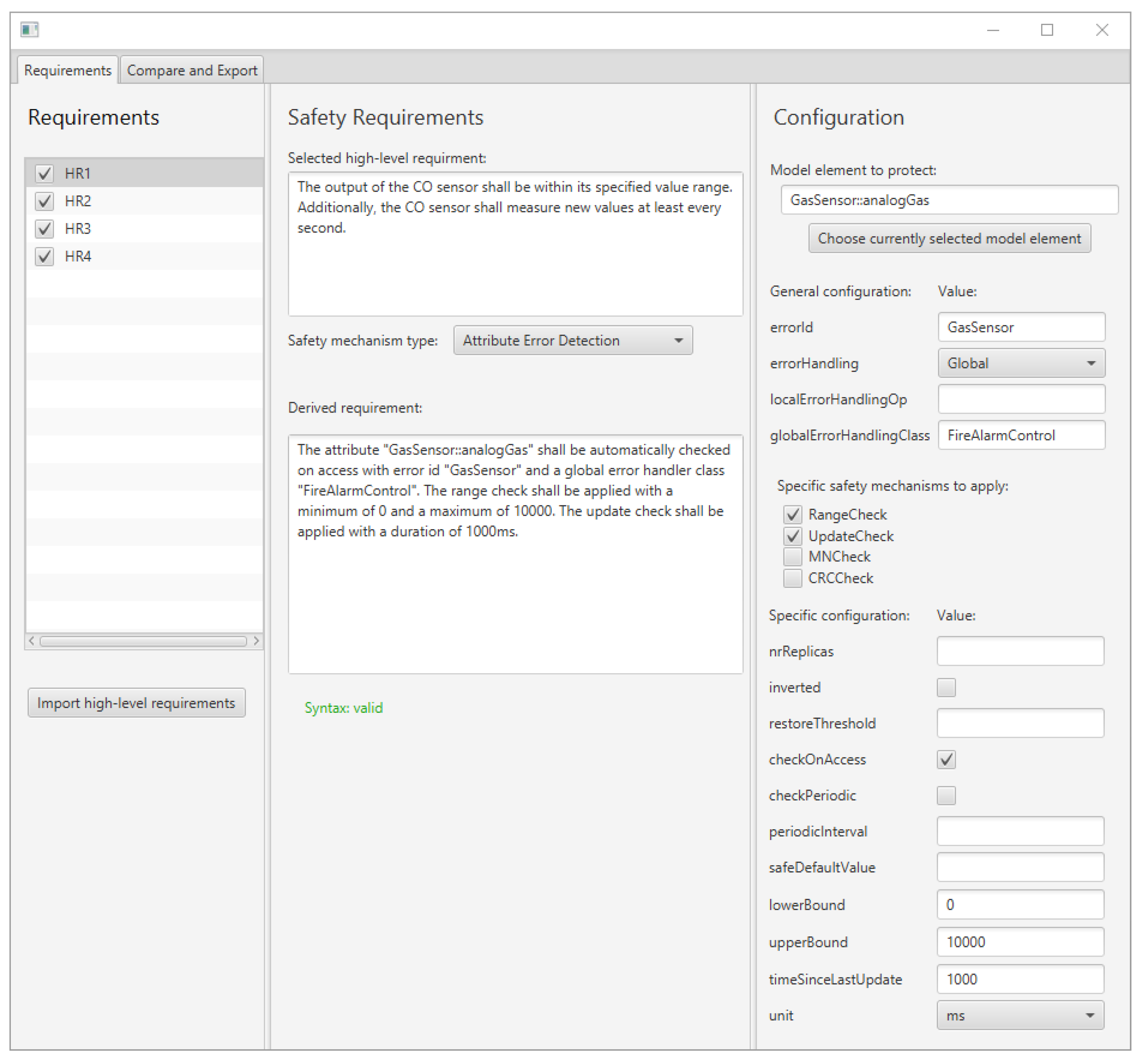
The output of the CO sensor shall be within its specified value range. Additionally, the CO sensor shall measure new values at least every second.
HR2:
The output of the temperature sensor shall be within its specified value range. Additionally, the temperature sensor shall measure new values at least every second.
HR3:
The output of the infrared sensor shall be within its specified value range. Additionally, the infrared sensor shall measure new values at least every second.
HR4:
The system shall check for a fire at least every second.
HR5:
The output of the sensors shall be compared in a voting process that determines the presence of a fire.
HR6:
The communication of the UART with the external hardware module sending an alarm SMS shall be protected with error-detecting codes.
The requirements HR1, HR2, and HR3 belong to the value and time domain and respectively monitor the operation of the CO, temperature, and infrared sensors. The requirement HR4 also belongs to the time domain. HR5 is derived from the recommendation for input comparison/voting for sensors, while HR6 belongs to the logical domain.
Using the sentence templates described in Section 5, the high-level requirements HR1–HR6 may be further refined to obtain a set of derived requirements. These derived requirements contain enough detail to enable the automatic code generation of safety mechanisms as outlined in Section 5, Section 6 and Section 7. Figure 3 shows these requirements for the application example.
The derived requirements correspond to the high-level requirements with the same number. Each sentence follows a given structure, i.e., which element should be protected by which safety mechanism and how it should be configured. Note that this structure differs for hardware- (DR6) and software-implemented safety mechanisms (DR1–5). The specification of the high-level and derived safety requirements is located in step 2 of the workflow shown in Figure 1.

4.2.3. Automatically Generating Software-Implemented Safety Mechanisms in the Application Example

The first step of the automatic generation process for software-implemented safety mechanisms is the application of safety stereotypes according to the detailed safety requirements presented in Section 4.2.2. This is step 3 in the workflow shown in Figure 1. Figure 4 shows the application example with the safety stereotypes. The following stereotypes have been applied:
  • Requirements DR1, DR2 and DR3 lead to the application of the < < RangeCheck > > and < < UpdateCheck > > stereotype to the attribute that represents the measured sensor value in the GasSensor, TemperatureSensor, and InfraredSensor classes.
  • Requirement DR4 leads to the application of the < < DeadlineSupervision > > stereotype to the operation checkForFire() in the class FireAlarmControl.
  • Requirement DR5 leads to the application of the < < MajorityVoter > > stereotype to the class FireDetector. Furthermore, the VotingInput stereotypes are applied to the association between FireDetector and the classes TemperatureFilter, InfraredFilter, and GasFilter.
The requirement DR6 is not considered in this section, as it deals with a requirement for a hardware-implemented safety mechanism. Next, model-to-model transformations are executed that create an intermediate model. In this intermediate model, the safety mechanisms indicated by the safety stereotypes have been realized in the model. This is step 6 of the workflow shown in Figure 1. The intermediate model contains only UML elements which may be mapped 1:1 to the target programming language. Thus, the code generation from the intermediate model is trivial.
Figure 5 shows the result of the model-to-model transformations. The following transformations have been performed:
  • The attributes with the < < RangeCheck > > and < < UpdateCheck > > stereotypes are replaced by instances of the class ProtectedAttribute, which performs the specified checks whenever the attribute is accessed, i.e., the operation getProtected() is called.
  • An instance of DeadlineSupervision has been added to the class FireAlarmControl. The method checkForFire(), to which the < < DeadlineSupervision > > stereotype is applied in Figure 4, has been automatically modified to start the monitoring process at is beginning and to stop and evaluate the monitoring at its end.
  • An instance of the class Voter has been added to the class FireDetector. Its vote() method performs majority voting, which has been indicated by the MajorityVoter stereotype applied to FireDetector in Figure 4. The method detectFire() has been automatically modified to pass the necessary inputs to vote() and return the value upon which the voting process agreed.
Note that for each safety mechanism that is added to the model, an instance of the class GlobalErrorHandler is added to the class that realizes the safety mechanism, e.g., to ProtectedAttribute. GlobalErrorHandler may access the class FireAlarmControl via the static getInstance() method, in order to provide error handling at the global level. This error handling is required in case any of the safety mechanisms described before has detected an error. In this application example, the global error handling consists of using the buzzer to sound a maintenance tone.

4.2.4. Automatically Configuring Hardware-Implemented Safety Mechanisms in the Application Example

The first step to automatically configure hardware-implemented safety mechanisms in the application example is to import the corresponding requirements in the GUI tool for configuring hardware interfaces. This is step 4 of the workflow shown in Figure 1. The GUI tool has been presented in [10] and is referred to as the PinConfig tool for the remainder of this article. An example of a requirement for a hardware-implemented safety mechanism is DR6 described in Section 4.2.2.
Figure 6 shows a screenshot of the PinConfig tool in which a Raspberry Pi has been configured in line with the application example. On the left, the available hardware interfaces for configuration are shown. The hardware interfaces that already have been configured are shown on the right. For the application example, this includes the UART which communicates with the external hardware module capable of sending an alarm SMS. Furthermore, it includes several GPIOs used for interacting with the sensors, the buzzer, and the button used to stop the alarm. The middle of the screenshot shows the pin layout of the Raspberry Pi and highlights which pins are currently in use.
While the pin allocation for the hardware interfaces has to be carried out manually by developers, any additional configuration may be automatically imported from the requirements. For example, the bottom right of Figure 6 shows that the interface UART0 uses a parity bit with an even mode, just as requirement DR6 states.
The functional application model of the application example initially shown in Figure 2 contains interfaces for interacting with the UART and the GPIOs (IGpio and IUart). The realization of these interfaces is dependent on the specific hardware platform used for the application. In this application example, they require an implementation for the Raspberry Pi that realizes the methods declared by the interface. The interfaces may be used to automatically generate the initial configuration of the hardware interfaces. For this purpose, a controller-specific template file that serves as a code snippet repository and the configuration from the PinConfig tool is used. For example, the GPIOs for the sensors have to be configured as input pins. Thus, for the CO sensor, a code line as shown in Listing 1 is automatically created.
Listing 1. Generated code for initializing the gas sensor GPIO as an input pin. The example uses the WiringPi library. The pin number 2 in WiringPi corresponds to the pin 13 in the physical layout and GPIO27 in the BCM numbering system.
pinMode(2, INPUT);
For each configuration in the PinConfig tool, the corresponding code, as exemplified in Listing 1, is generated. The generated files may be subsequently included during compilation. Furthermore, they may be integrated with the UML model by using the automated reverse engineering capabilities of the MDD tool. These steps have been combined in step 5 of the workflow shown in Figure 1.

5. Specifying Safety Requirements to Enable Automatic Code Generation

This section describes sentence templates that enable the specification of safety requirements in a way that enables automatic code generation. It is conceptually located in action 2 of the overview shown in Figure 1.

5.1. Sentence Templates for Specifying Safety Mechanisms

In this article, we use the term sentence template to refer to a structured sentence with placeholders. These placeholders are replaced with specific values when a safety requirement is specified, e.g., the location of the model element to which a safety mechanism should be applied. Based on the examples provided in Section 4.2.2, we define the following characteristics which the sentence templates need to be able to express:
  • Both software- and hardware-implemented safety mechanisms have to be expressible with the sentence templates. For example, the high-level requirements HR1–HR5 presented in Section 4.2.2 refer to software-implemented safety mechanisms, while HR6 refers to a hardware-implemented safety mechanism.
  • The type of model element that should be protected has to be expressible with the sentence template. For example, the first sentence of HR1 refers to specific values measured by the sensor, i.e., an attribute in the model. Requirement HR4, in contrast, refers to an action, i.e., checking for fire. This corresponds to a method within the model.
  • The specific type of safety mechanism has to be expressible with the sentence templates. For example, HR6 only refers to “error detecting codes”. However, “error detecting codes” refers to a category of safety mechanisms with distinct realizations, e.g., whether a Cycling Redundancy Check (CRC), a Hamming code or a parity bit is used.
  • The configuration of safety mechanisms has to be expressible with the sentence templates. For example, for HR1 it is not sufficient to only specify which element should be protected regarding the sensor’s output range. Instead, the upper and lower limit of this range also have to be specified. Another example is HR6. Even a specific error-detecting code, e.g., CRC, may have multiple configuration options, e.g., the number of bits used for the code.
In the following subsections, we propose a set of sentence templates that fulfill the above characteristics. The sentences are formulated in ANTLR (ANother Tool for Language Recognition) [64] syntax.

5.1.1. Distinction between Hardware- and Software-Implemented Safety Mechanisms

As described in Section 2.2, the generation of hardware-implemented safety mechanisms is limited to the automatic initial configuration of these mechanisms in this article. This configuration is ultimately achieved by using the respective functions provided by the Application Programming Interface (API) of a microcontroller. These functions often follow a key-value approach. The name of the API method serves as the key for the property of the hardware-implemented safety mechanism that should be configured. The parameters of the API method indicate the value to which this property should be set.
For software-implemented safety mechanisms, there exists no equivalent to the above-mentioned API for hardware-implemented safety mechanisms. Furthermore, this article covers the full code generation for software-implemented safety mechanisms, adding more complexity than only configuring the initial configuration of these mechanisms. Thus, we distinguish the sentence templates for hardware- and software-implemented safety mechanisms as their required level of complexity differs significantly from each other. Consequently, the first rule of the ANTLR grammar, shown in Listing 2 reflects this distinction:
Listing 2. Distinction of safety requirements depending on whether they are implemented in software or hardware (ANTLR syntax).
req: swReq | hwReq

5.1.2. Sentence Templates for Hardware-Implemented Safety Mechanisms

As stated in Section 5.1.1, the configuration of hardware-implemented safety mechanisms is a set of key-value assignments for a specific hardware element. Thus, the sentence template consists of the hardware interface that should be protected, as well as a list of the key-value assignments. The structure of the template is shown in Listing 3.
Listing 3. Sentence template for a hardware-implemented safety requirement. The angle brackets indicate a placeholder.
The hardware element <Name of the hardware interface to be protected> shall be protected with the configuration "<key>" as "<value>".
The <key> and <value> elements of this template may be used multiple times to configure multiple values. Listing 4 shows the ANTLR grammar for this sentence template.
Listing 4. ANTLR grammar for a hardware requirement. The QSTRING lexer rule refers to a rule that can parse strings surrounded by quotes.
hwReq: ‘The hardware element ‘hwId’ shall be protected with the configuration’
hwConfig ‘.’;
hwId: QSTRING;
hwConfig: hwConfigEntry ((‘,’ | ‘and’) hwConfig)*;
hwConfigEntry: QSTRING ‘as’ QSTRING;
The hwConfig parser rule states that a hardware element may have one to an arbitrary number of configuration entries. Each configuration entry (hwConfigEntry) uses two strings to define the key (type of safety mechanism) and value (configuration of this safety mechanism) for a single configuration. The indicated key and value for a configuration have to be valid arguments for the hardware element specified by hwId. The validity of the arguments is checked during the integration with the PinConfig tool and is further described in Section 7.

5.1.3. Sentence Templates for Software-Implemented Safety Mechanisms

Due to the higher degree of configurability for software-implemented safety mechanisms compared to hardware-implemented safety mechanisms, the sentence template for software-implemented safety mechanisms distinguishes between a general and a specific configuration of the mechanism.
Listing 5 shows the sentence template for software-implemented safety mechanisms. It includes the category of the safety mechanism that should be applied, e.g., timing constraint monitoring. General configuration values follow, i.e., those that are applicable to all safety mechanisms belonging to this category. Next, the specific safety mechanism is specified, e.g., the specific form of timing constraint monitoring (deadline supervision in Listing 5. The configuration of this specific mechanism follows. Multiple specific safety mechanisms of the same category may be applied to the same model element, e.g., as shown in requirements DR1-DR3 described in Section 4.2.2. The ANTLR grammar for software-implemented safety mechanisms is shown in Listing 6.
Listing 5. Sentence template for a software-implemented safety requirement. The angle brackets indicate a placeholder.
The <model element to be protected> <general safety mechanism type> <general configuation>. <specific safety mechanism to be applied> <specific configuration>.
Listing 6. ANTLR grammar for a software requirement. The QSTRING lexer rule refers to a rule that can parse strings surrounded by quotes. The parser rules swConfig and swSharedConfig are not defined in the listing, but further described in the main text. The same applies to the lexer rules TYPE_ATTRIBUTE_CHECKS, TYPE_VOTING and TYPE_TIMING_MONITORING.
swReq: introReq (addReq)*
introReq: ‘The ‘location’ shall be ‘introHow’ with ‘swSharedConfig’’.;
addReq: ‘The ‘type’ shall be applied ‘(‘to the’ location)?’ with ‘swConfig’’.;
location: locationType SPACE locationPath;
locationType: ‘class’ | ‘attribute’ | ‘operation’ | ‘association with’:
locationPath: QSTRING;
introHow: ‘automatically checked on access’ | ‘periodically checked every TIME_UNIT ’ | ‘used for voting’ | ‘monitored regarding its runtime’;
swSharedConfig: swSharedConfigEntry ((‘,’ | ‘and’) sharedConfig)*;
type: TYPE_CHECKS | TYPE_VOTING | TYPE_TIMING_MONITORING;
swConfig: swConfigEntry ((‘,’ | ‘and’) swConfig)*;
The sentence template contains an introduction statement for a software element that should be protected (introReq). In the context of this article, these software elements are UML elements, because the code generation approach described in Section 6 uses UML. An arbitrary number of statements follows, each of which describes a safety mechanism that should be applied to the software element (addReq).
The software element that should be protected is defined by its type (locationType), as well as the full path to its location in the development project (locationPath). Furthermore, the introduction statement defines the general category of safety mechanism that should be applied for this software element (introHow). For this, we defined phrases that fit with the (natural) grammar of the sentence template. Multiple safety mechanisms of the same category may be applied to the same software element. Thus, we use the value swSharedConfig to specify those configuration values that apply to all safety mechanisms applied to this software element. For example, this could be the method of error handling in case a safety mechanism has detected an error.
Details regarding specific safety mechanisms are described in the addReq parser rule. It specifies the concrete type of the safety mechanism (type), as well as the configuration values that are only relevant for this specific safety mechanism (swConfig). Additionally, addReq may optionally reference a second location that is relevant for the safety mechanism, e.g., in case an association to another class is involved. An example of this is the requirement DR5 presented in Section 4.2.2.
In Listing 6, the type parser rule resolves into three lexer rules, TYPE_ATTRIBUTE_CHECKS, TYPE_VOTING, and TYPE_TIMING_MONITORING. The values that may be assumed by these lexer rules correspond to the names of UML stereotypes. These stereotypes are defined in UML profiles, each of which contains stereotypes for a category of safety mechanisms. Such profiles are discussed in-depth in Section 6. The stereotypes contained within these profiles define tagged values that may be used to configure a safety mechanism. The parser rules swConfig and swSharedConfig are used to specify the values for these tagged values. These rules require entries for each stereotype of the aforementioned UML profiles. They are sentence fragments that fit grammatically in the sentence structure and contain information about a configuration value. An example for this is the sentence fragment “with a time limit of 1000 ms” that is used at the end of requirement DR2 described in Section 4.2.2. For brevity, the swConfig and swSharedConfig rules are not shown in Listing 6.

5.2. Prototype Implementation

We have developed a GUI prototype that enables developers to specify detailed safety requirements according to the sentence templates presented in Section 5.1. Figure 7 shows a screenshot of this prototype. On the left of Figure 7, users may select a high-level requirement, e.g., as described in Section 4.2.2 In the middle of Figure 7, the text of the high-level requirement is shown, as well as the corresponding derived requirement. The derived requirement may either be typed by hand or automatically constructed by filling the textfields in the right compartment of Figure 7. Thus, the prototype enables users to construct detailed safety requirements for the purpose of the automatic code generation of the specified safety mechanisms.
As the derived safety requirements conform to the ANTLR grammar presented in Section 5.1, they may be parsed automatically. The corresponding values are stored in the form of Java objects. These serve as the input for the code generation approaches for software-implemented safety mechanisms (cf. Section 6) and hardware-implemented safety mechanisms (cf. Section 7). The Java objects each contain the name of a hardware or software element that should be protected according to the derived requirement. Furthermore, they contain a list of safety mechanisms and the configuration that should be applied to this element.

6. Model-Driven Code Generation of Software-Implemented Safety Mechanisms

This section describes the model-driven code generation of software-implemented safety mechanisms. It is conceptually located in actions 3 and 6 of the overview introduced in Figure 1. The basic idea is to use UML stereotypes to annotate UML elements with safety mechanisms. These mechanisms are subsequently realized via model-to-model transformations.

6.1. Automatically Applying Safety Stereotypes to the Application Model

The sentence templates presented in Section 5 may be used to automatically apply corresponding UML stereotypes in the application model. For this purpose, we developed a prototype application whose input is a map M. Its keys are the name of UML elements. The corresponding value to each key is a list. This list contains information about the safety requirements for the model element specified in the key. How this map may be generated from the requirements has been described before in Section 5.2.
The prototype is a Java application that utilizes the Java API of the MDD tool IBM Rhapsody [8] to interact with Rhapsody’s UML models. It iterates through the keys of M and attempts to locate the corresponding UML elements in the application model. For each element that is successfully located, each stereotype that is applied to this element is compared to the information contained in M about this model element. Every difference between the actual applied stereotypes and the information from the requirements is stored temporarily until all elements in M have been processed. Subsequently, this process is reversed. The entire application model is iterated. All UML elements to which a safety stereotype has been applied are compared to the objects in M that describe the requirements. For each comparison where there exists no corresponding requirement in M for a safety stereotype, this difference is also stored temporarily. All the differences between the applied stereotypes and the information from the requirements are subsequently displayed to the developer in the tab “Compare and Export” of the GUI previously shown in Figure 7. There, the developer may review the differences and automatically update the information of the stereotypes in the application model according to the requirements.

6.2. Error Detection and Error Handling: Runtime Behavior

Safety mechanisms may detect runtime errors in applications. Once such an error has been detected, error handling has to be executed in order to return the system to a safe state. We identify several error-handling strategies that ultimately converge to the normal control flow of the application that would exist when no safety mechanisms are present in this system. This convergence is necessary for an automated approach to the model-to-model transformations. A non-temporary deviation from the normal control flow would require additional, manual changes in the application model. These changes would be required in order to account for the deviation in the application’s behavior after the model transformations.
EH1:
Error handling executed as part of the error detection mechanism. Some error detection mechanisms, e.g., CRC, are capable of handling errors without any extra safety mechanism. In the case of CRC, this would be the correction of the malformed bits. This type of error handling may be generated alongside the generation of error detection mechanisms.
EH2:
Error handling executed by a dedicated error handling safety mechanism. Some safety mechanisms that focus on error handling strategies may be generated automatically, e.g., graceful degradation [16].
EH3:
Error handling that is manually implemented. In some cases, error handling may require application-specific knowledge. This prevents full automatic code generation. For example, before an application exhibits fail-stop behavior, application-specific shut down procedures may have to be triggered. As these may vary for different applications, some amount of manually implemented code is not avoidable. The approach described in this article aims to support such manually implemented error handling by automatically generating the infrastructure around the actual error handling. Developers only have to implement the error handling method. The code for the invocation of this method, i.e., when an error has been detected, is generated automatically. This article presents two types of manually implemented error handling. The first type functions in a local scope, i.e., a manually implemented operation inside the class in which an error is detected. The second type functions at a global scope via a global singleton and may therefore affect larger parts of the application. This error handling at the global scope is realized in the application example described in Section 4.2.1, where the code for the handleError() method inside the class FireAlarmControl had to be written manually. However, the invocation of this method at the right moment, i.e., after an error has been detected, has been automatically generated.
Figure 8 shows how these different types of error handling interact at runtime. In case the error detection mechanism that was responsible for detecting the error contains in-built error handling capabilities (cf. EH1), these are executed first (cf. action 1 in Figure 8). Examples for this are the aforementioned CRC scenario and restoration from replicas in the M-out-of-N pattern [65]. If the error has been corrected this way, the normal control flow resumes (cf. action 3 in Figure 8). In case the error has not been corrected in action 1, another attempt at error handling is initiated in action 2. This is either a dedicated error handling mechanism (cf. EH2) or manually implemented error handling (cf. EH3). Which type of error handling is executed in action 2 is decided by developers by configuring the tagged values of the respective stereotypes. After action 2 has been performed, the normal control flow resumes (cf. action 3 in Figure 8).

6.3. Model Representation

This section discusses the model representation of software-implemented safety mechanisms with UML stereotypes. Because such stereotypes for specific safety mechanisms have already been proposed [15,16,17,18,19], we focus on how these approaches may be integrated into a single holistic model representation. For this, it is relevant to know that each of the approaches in [15,16,17,18,19] defines its own UML profile with stereotypes focused on one specific category of safety mechanisms. For example, stereotypes focused on safety mechanism voting are grouped in one profile. These different profiles may be imported into a single UML profile which contains the stereotypes for several categories of safety mechanisms. Thus, developers only have to apply one profile to their projects. This is shown in Figure 9, which consists of three layers.
The top layer contains the development project for a safety-critical system (ExampleProject). Developers may use safety stereotypes that enable automatic code generation of safety mechanisms by applying the SafetyGen profile to their project. This profile encompasses several sub-profiles, each of which provides stereotypes for a specific safety mechanism. Thus, SafetyGen is the only profile developers need to apply to their project. The middle layer contains UML profiles that each describe stereotypes for a specific safety mechanism, e.g., SafetyMechanism1. The profiles in this layer, for example, may be the profiles presented in [15,16,17,18,19]. In order to provide an overarching framework for these stereotypes and the subsequent code generation, the bottom layer introduces the profile SafetyGenBasic. It provides stereotypes from which the stereotypes of the middle layer should inherit. The SafetyGenBasic profile is shown in Figure 10.
The < < ErrorDetector > > stereotype is intended as a top-level stereotype from which stereotypes modeling specific error detection mechanisms should inherit. For example, the < < DeadlineSupervision > > , < < RangeCheck > > , < < UpdateCheck > > , and < < MajorityVoter > > stereotypes used in the application example in Section 4.2 inherit from this stereotype. The < < ErrorDetector > > stereotype provides a set of tagged values. These enable developers to configure how an error, detected by this safety mechanism, should be handled. For this purpose, they may specify an id for the error and determine the type of error handling. Optionally, in case the error handling type is Local or Global, the name of a method for local error handling or the name of a globally accessible class for global error handling may be specified by the developer.
The error handling type is configured via an enumeration whose values corresponds to the error handling approaches described in Section 6.2. The values “Local” and “Global” correspond to manually implemented error handling (cf. EH3 in Section 6.2). The values “DedicatedErrorHandlingMechanism1” and “DedicatedErrorHandlingMechanism2” serve as placeholders for an error handling mechanism that may also be automatically generated via MDD (cf. EH2 in Section 6.2).
The error handling strategy EH1 presented in Section 6.2 is not represented via an enumeration value, because this type of error handling is inherent to each error detection mechanism. Thus, it is always generated as part of the error detector and its usage is modeled via the specific error detection stereotype, e.g., it is modeled within the specific stereotype < < RangeCheck > > instead of the top-level stereotype < < ErrorDetector > > .

6.4. Software Architecture

In order for the model-to-model transformations that generate the safety mechanisms to be fully automatic, any changes to the application model have to be transparent to the developer. Thus, a software architecture is required that enables such a transparent realization of safety mechanisms. Figure 11 shows an example UML class diagram for this purpose. It assumes that the class ProtectedClass should be protected by a software-implemented safety mechanism. For this purpose, an instance of a class representing this safety mechanism, ConcreteErrorDetector, is added to the class that should be protected. This class realizes an interface that provides a method for performing an error detection check (check()). ConcreteErrorHandler instantiates exactly one error handler, which it calls in case the check() method has detected an error. Figure 11 shows three alternative error handlers, which belong to the error handling strategies EH2 and EH3 described in Section 6.2. The error handling strategy EH1, if applicable for this error detection mechanism, is realized inside ConcreteErrorDetector, as it depends on its implementation details (method handleErrorByMechanism()).
A template parameter, TErrorHandler is used to indicate the type of error handler that should be instantiated by ConcreteErrorDetector. This way, an implementation of ConcreteErrorHandler may use an arbitrary error handler. Additionally, other template parameters may be used to configure the instantiated classes. For example, the error handler LocalErrorHandler requires a function pointer to a method of the protected class. This, in turn, requires that the type of the protected class is also a template parameter (TProtected).
The class names shown in Figure 11 are generic and represent placeholders for actual classes. For the ongoing application example previously shown in Figure 5, the classes FireAlarmControl, FireDetector, TemperatureSensor, InfraredSensor, and GasSensor are all examples for ProtectedClass. The classes DeadlineSupervision, Voter, and ProtectedAttribute, on the other hand, are examples for specific classes of ConcreteErrorDetector. The class FireAlarmControl serves as an example for GlobalErrorHandlerSingleton.

6.5. Model Transformations

Section 6.3 and Section 6.4 have discussed a model representation and a software architecture for safety mechanisms. In order to automatically generate safety mechanisms, model transformations between the concepts presented in these sections are required. For these, the information from the UML stereotypes describing the safety mechanisms has to be parsed from the model. This includes the element to which a relevant stereotype is applied, as well as the tagged values of this stereotype. Relevant stereotypes, in this case, are those that are contained in the “SafetyGen” UML profile presented previously in Figure 9. For each of these parsed stereotypes, the following steps have to be performed:
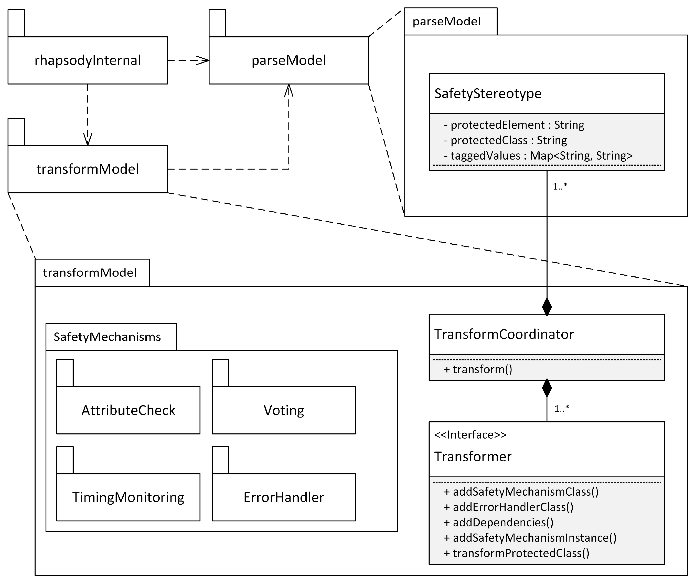
  • The addition of a class that represents the safety mechanism modeled by the stereotype (cf. ConcreteErrorDetector) in Figure 11.
  • The addition of a class that represents the error handler used by the safety mechanism (cf. ErrorHandler and its interface realizations in Figure 11).
  • The addition of the necessary dependencies to the class that should be protected (cf. ProtectedClass in Figure 11). This includes any dependencies to classes created by the model transformations, e.g., the two classes mentioned above. The class that should be protected may be directly marked with a stereotype, e.g., class FireDetector in Figure 4. Alternatively, the protected class is the class that contains the model element with a safety stereotype. For example, in Figure 4, the sensor classes are classes that should be protected. The reason for this is that they each contain an attribute with at least one safety stereotype, i.e., < < RangeCheck > > and < < UpdateCheck > > .
  • The addition of an instance to the protected class that should be protected. The instance added to this class realizes the safety mechanism. In terms of Figure 11, an instance of ConcreteErrorDetector is added to ProtectedClass. ConcreteErrorDetector uses template parameters to reflect the configuration options of the tagged values of the safety stereotypes. Thus, these template parameters also have to be set accordingly.
  • Additional changes to the protected class may be necessary, depending on the generated safety mechanism. For example, consider the getter methods of the sensors in the application example shown in Figure 11. These have to be modified to no longer directly return the value of an attribute. Instead, they have to call the getProtected() method of the corresponding ProtectedAttribute instance, which performs the error detection checks before returning the value of the attribute.
Note that for all additions to the model, it is necessary to check whether the model element that should be added already exists within the model. For example, in the application example shown previously in Figure 5, the class ProtectedAttribute is only added once to the model instead of once for each sensor.

6.6. Prototype Framework

We implemented a prototype that implements the model transformation steps described in Section 6.5 in a prototype implementation. This implementation is an extensible framework to which new safety mechanisms may be added in the future. The framework targets models created with the MDD tool IBM Rhapsody [8] and uses its Java API to interact with the model. However, the presented concepts may be transferred to other MDD tools and model transformation languages, e.g., the MDD tool Papyrus [9] with the Epsilon model transformation language [66]. Figure 12 shows the software architecture of the prototype.
The framework consists of three Java packages. The package rhapsodyInternal is responsible for embedding the model transformations in Rhapsody’s code generation process. The package parseModel provides functionality to extract the information of safety stereotypes from the model. It also stores this information for each stereotype in an object of the class SafetyStereotype. This information is used in the package transformModel, in which the class TransformCoordinator executes the necessary model transformations for each stereotype. This is achieved by invoking the methods of the Transformer interface, whose methods correspond to the necessary transformation steps described in Section 6.5. Realizations of the Transformer interface are located in the SafetyMechanisms package (or its subpackages). We use Java reflection mechanisms to automatically instantiate a class that realizes the Transformer interface for a given safety stereotype. For this purpose, the realizations have to follow a naming convention, i.e., the class name consists of the name of the safety stereotype followed by the word “Transformer”, e.g., MajorityVoterTransformer.
New safety mechanisms may be added to the framework by creating a class inside the SafetyMechanisms package. This class has to realize the Transformer interface and follow the naming convention described above. No further steps are necessary, as the class is instantiated automatically by the reflection mechanism in case a corresponding safety stereotype is parsed from the model.

7. Automatic Code Generation of the Initial Configuration of Hardware-Implemented Safety Mechanisms

This section describes an approach for the automatic code generation of the initial configuration of hardware-implemented safety mechanisms. It is conceptually located in actions 4 and 5 of the overview introduced in Figure 1. The basic idea is to use a GUI tool for configuring the initial properties of hardware interfaces, as well as their pin mapping. The configuration from this GUI tool may then be used for generating the source code that executes these configurations by using a set of appropriate template files. In the context of this article, we consider hardware-implemented safety mechanisms to be a subcategory of general hardware interfaces (cf. Section 2.2). Thus, providing the aforementioned configuration for general hardware interfaces also provides the automatic configuration for hardware-implemented safety mechanisms.

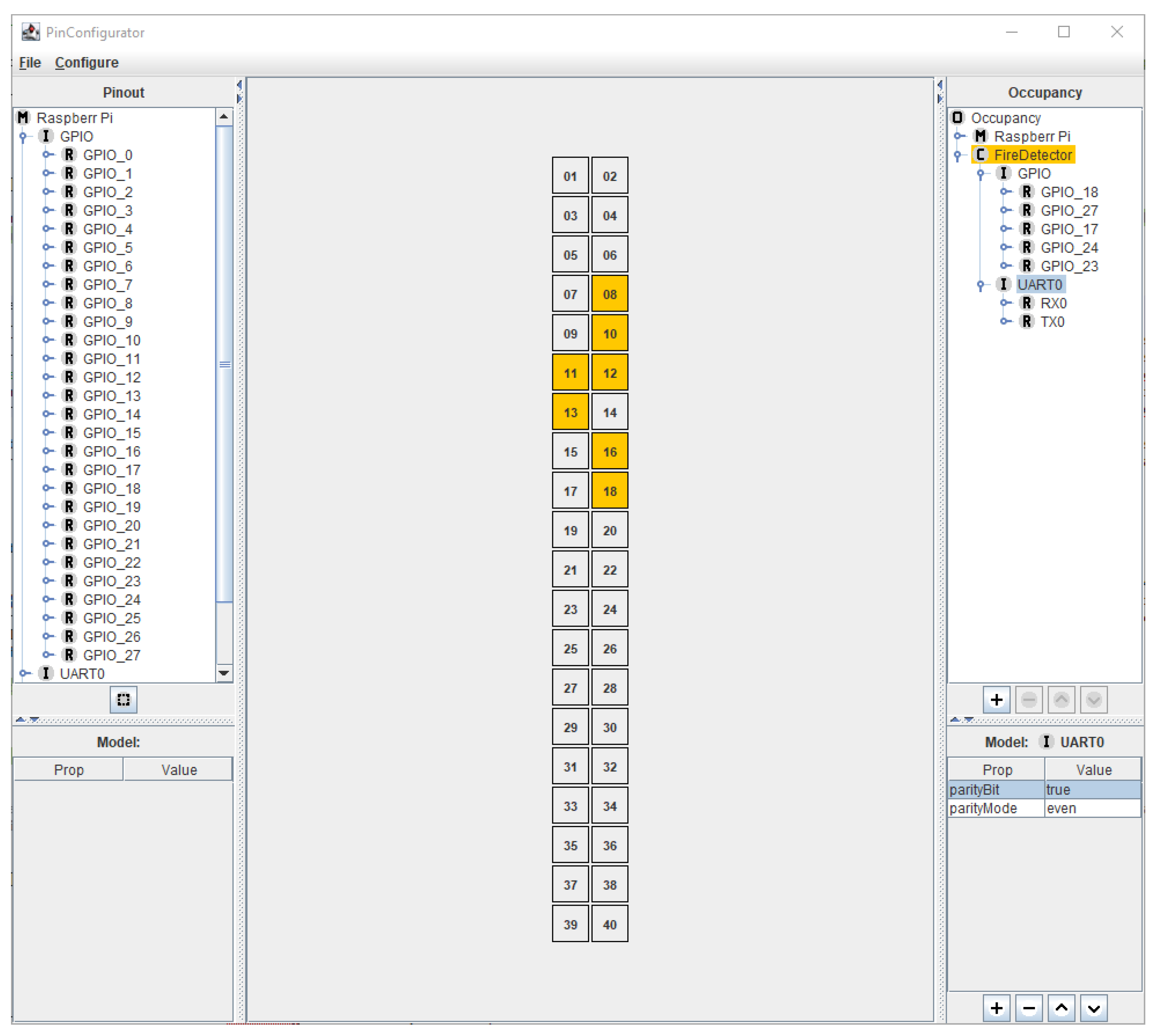
7.1. Automatically Configuring Hardware Interfaces in the PinConfig Tool from Requirements

The automatic code generation for the initial configuration of the hardware interfaces is performed by the PinConfig tool. For this, the PinConfig tool has to be configured properly. This configuration may be automated, by importing a list of hardware safety requirements as generated by the process described in Section 5.2. The result is a map A of key-value pairs for each hardware interface. For example, requirement DR6 (cf. Section 4.2.2) states that for the hardware interface “UART0” the key “parityBit” should be set to “true”. The PinConfig tool stores its internal representation of the configuration of hardware interfaces in a map B that is of a similar structure as map A. Thus, configuring the hardware interfaces in the PinConfig tool comes down to iterating through every entry in A and setting the values in B accordingly.

7.2. Code Generation of the Initial Configuration of Hardware Interfaces

The code generation process for the initial configuration of hardware interfaces has been described in [10]. While this process is not modified in this paper, this section provides a succinct summary of the general approach to aid in the understanding of the approach presented in this article.
Figure 13 shows an overview of the source code artifacts that exist at the end of the code generation process. Code that is not directly interacting with hardware is located in the app directory, e.g., the code that may be generated from the application model of the application example as shown in Figure 5. This code uses interfaces for interacting with hardware that are located in the interfaces directory. Essentially, this directory provides the functionality of a HAL. The controller-specific implementation of this HAL is located in the directory internal.
The configuration generated from the PinConfig tool is located in the files platform.h and platform.cpp. They contain statements as shown exemplarily in Listing 1. Both files are generated automatically with the aid of the file platform_template.xml, which is a controller-specific template file that contains code snippets with placeholders. The placeholders are filled in automatically by using the information about the configuration from the PinConfig tool.
To integrate this approach with MDD tools, it is at least necessary that the app and interfaces directory are present within the model of the MDD tool. The internal directory and the platform.h and platform.cpp files only have to be included during compilation. Nevertheless, it is possible to include these files in an MDD tool via automated reverse engineering provided by these MDD tools. In the overview of the approach shown previously in Figure 1, this code generation process and the subsequent integration within the model is located in action 5.

8. Evaluation

This section evaluates the proposed approach by studying the scalability of the model transformations involved, as well as the efficiency of the generated code.

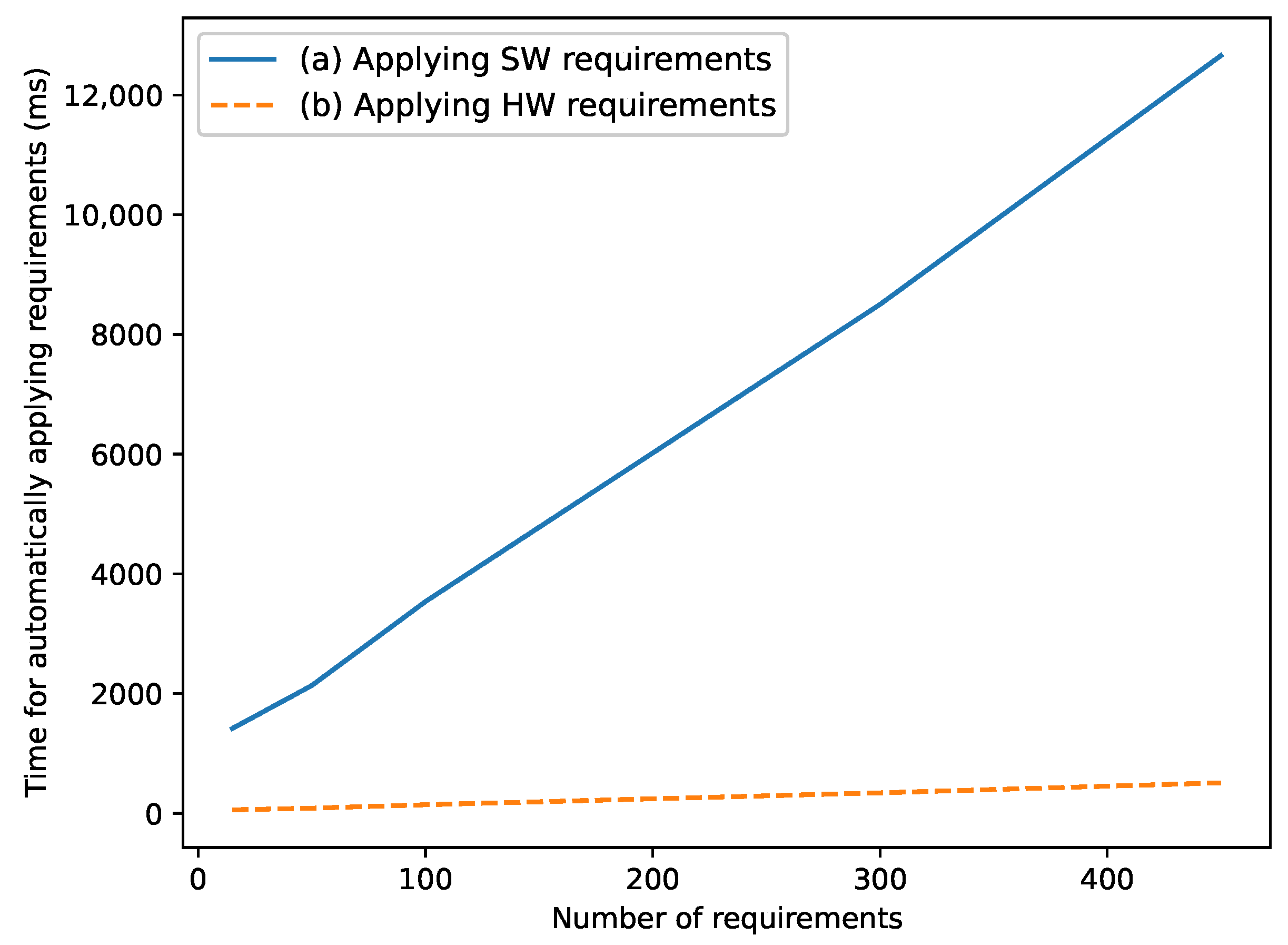
8.1. Scalability of Model Transformations

A high execution time of the concepts presented in Section 5, Section 6 and Section 7 time may unnecessarily impede the workflow of a developer. This is especially true for the concepts presented in Section 6, which are executed every time code is generated from the model. To a lesser extent, it also applies to the concepts presented in Section 5 and Section 7, which need to be executed in case the safety requirements or the hardware configuration changes. The following subsections evaluate the runtime of the involved model transformations.
All experiments are conducted on a “Dell Precision M4800 Workstation” notebook, which contains an Intel Core i7-4810MQ processor running at 2.80 GHz and 32 GB RAM. Each measurement is repeated ten times and the arithmetic mean is used for evaluation in order to reduce any influences of the operating system scheduling on the runtime. Windows 10 is used as the operating system.

8.1.1. Runtime of Requirements Parsing

This section evaluates the runtime required for parsing the derived safety requirements formulated according to the concepts presented in Section 5, as well as applying the corresponding model representation for these safety mechanisms in the UML model (for software-implemented safety mechanisms) or in the PinConfig tool (for hardware-implemented safety mechanisms). For this purpose, we generate random requirements that comply with the syntax presented in Section 5 and measure the runtime of the subsequent parsing and model integration process. The results are shown in Figure 14, which shows a linear runtime of this process for both hardware- and software-implemented safety mechanisms. This linear runtime occurs because a fixed number of steps are performed for each requirement.
The measured runtime differs for hardware- and software-implemented safety mechanisms. For both, the runtime for parsing the requirements with the ANTLR framework is comparable with each other and takes between 50 to 500 ms. For hardware-implemented safety mechanisms, the subsequent actions consist of setting the parsed values within the PinConfig tool. This has a negligible runtime (<50 ms). Thus, for hardware-implemented safety mechanisms, the parsing process makes up the bulk of the runtime. For software-implemented safety mechanisms, the parsed values are used to construct and apply stereotypes in the UML model with the Rhapsody API. The API calls of the Rhapsody API are comparatively slow to the PinConfig tool, which leads to the large difference in runtime for both types of safety mechanisms.
As the requirements only have to be applied to the model whenever one or more requirements change, the total runtime of less than fifteen seconds (for 400 requirements) does not hinder the developer’s workflow in the authors’ subjective opinion.

8.1.2. Runtime of Model Transformations

This section evaluates the runtime required for generating the software- and hardware-implemented safety mechanisms according to the concepts presented in Section 6 and Section 7. For this purpose, we randomly create model representations for both types of safety mechanisms. For software-implemented safety mechanisms, this means random UML stereotypes applied to valid model elements. For hardware-implemented safety mechanisms, this means the appropriate configurations in the PinConfig tool. For the evaluation, we measure the runtime of the generation steps. The generation of hardware-implemented safety mechanisms ultimately depends on the number of physical hardware interfaces on the studied microcontroller. Thus, we use a much smaller number of generated elements for them than for software-implemented safety mechanisms. For the hardware interfaces, code for a mix of GPIO and UART interfaces has been generated. For the software-implemented safety mechanisms, the three types implemented in Section 6.6 have been studied, i.e., error detection for attributes, voting, and timing constraint monitoring.
Figure 15 shows the results of the measurements. Both generation types scale linearly with the number of generated elements. This is explained by the fact that a fixed number of actions is performed for the generation of each element. The runtime for the three different types of software-implemented safety mechanisms is roughly equivalent from a practical perspective. Even for a large number of 200 safety mechanisms the total runtime is below one second. The runtime for the generation of hardware-implemented safety mechanisms is comparatively larger, even for a much smaller number of generated elements. The actual code generation process based on the template-based code snipped repository (cf. platform_template.xml in Section 7.2) only makes up a fraction of this runtime (below one second), while the bulk of the runtime happens during the automatic reverse engineering process that integrates the generated code within the Rhapsody UML model.
The transformations for the hardware-implemented safety mechanisms only have to be executed when the initial configuration of the target hardware is changed in the development project. Thus, the generation process only occurs sporadically. Therefore, it does not hinder a developer’s workflow in the authors’ subjective opinion. The transformations for the software-implemented safety mechanisms, on the other hand, are executed each time a developer creates code from the application model. This process occurs regularly during a developer’s workflow. However, the (subjectively) low amount of time required for the additional generation of the safety mechanisms indicates that the workflow of the developer is not hindered by the additional transformations.

8.2. Setup for Evaluating the Overhead of the Generated Code at Target-Level

Section 8.3 and Section 8.4 evaluate the overhead of the generated safety mechanisms at the target level, i.e., the additional memory usage and runtime that occurs by including the generated safety mechanisms within an application. As the target platform, a Raspberry Pi4B is used with the Raspbian operating system. The overhead measurements are only conducted for the software-implemented safety mechanisms presented in Section 6. For the initial configuration of hardware-implemented safety mechanisms described in Section 7, the memory overhead is limited to a few lines of code that are used to instruct the microcontroller to initiate the configuration. No additional data is stored at the application level. The runtime overhead of these hardware-implemented safety mechanisms, in turn, depends on the specific microcontroller at hand and is not dependent upon the concepts presented within this article.
To improve their readability, Section 8.3 and Section 8.4 use the abbreviations EDA (Error Detection for Attributes) and TCM (Timing Constraint Monitoring) to refer to groups of safety mechanisms. EDA encompasses TMR, and the Range, Update and CRC check. TCM includes deadline supervision and two watchdog-based timing checks (cf. Section 2.1 for a description of these mechanisms).

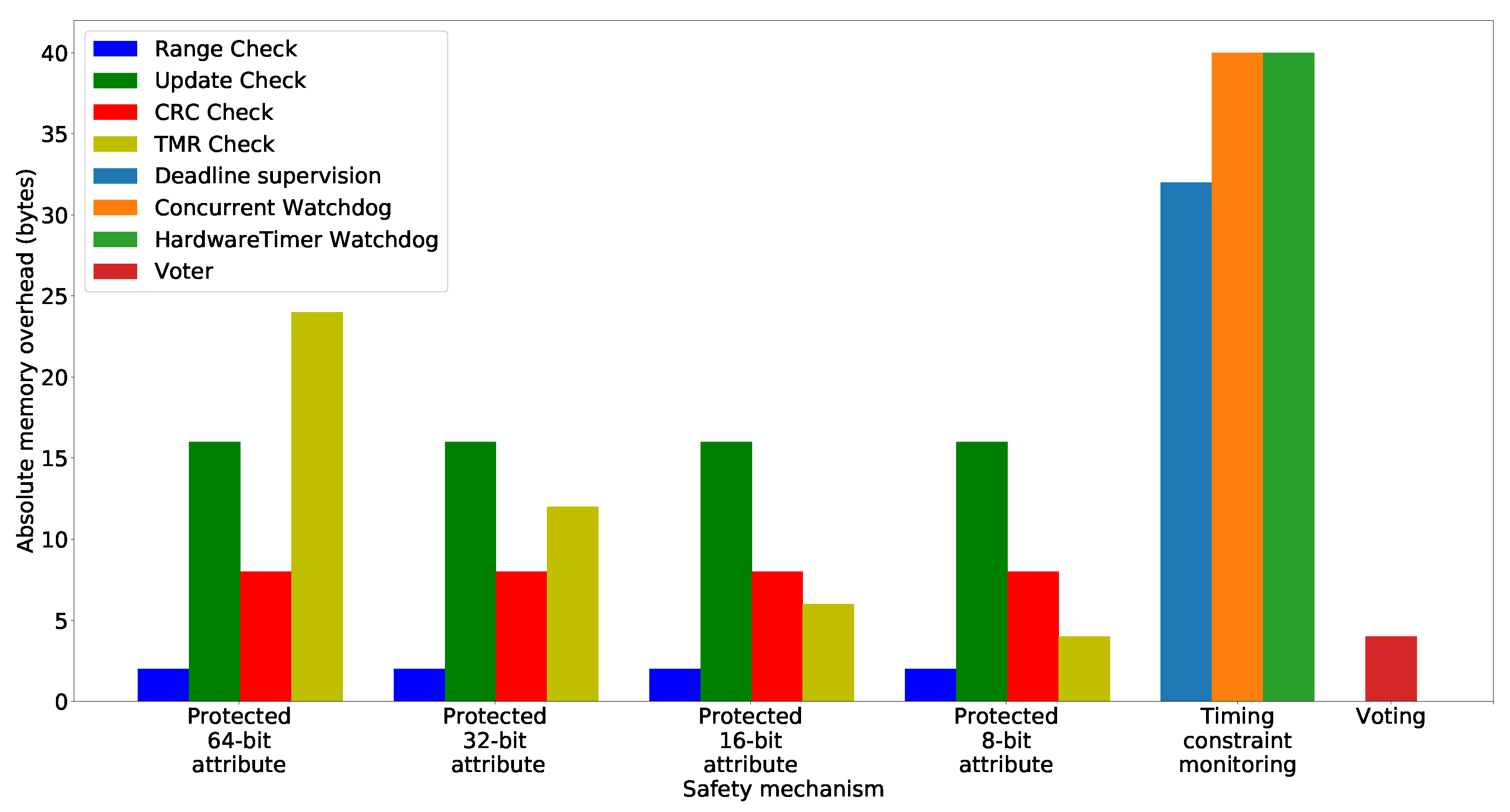
8.3. Evaluation of the Memory Overhead at Target-Level

Safety-critical systems are often embedded systems which in turn are implemented on microcontrollers with limited resources, e.g., memory. A small memory overhead allows for the usage of the concepts presented in this article on a wide variety of these devices. For the experiment setup, recall that the software-implemented safety mechanisms are added via composition to existing classes. For these composite mechanisms, the memory overhead is measured by using the inbuilt C++ operator sizeof. This operator measures the number of bytes allocated for a given data type. In this case, the data type used for the sizeof operator is the composite error detection object added to the existing class.

8.3.1. Results: Absolute Memory Overhead

The absolute memory overhead of the generated safety mechanisms at the target level is shown in Figure 16. The results show that the absolute memory overheads for the Range, Update, and CRC check are independent of the size of the protected attribute. Only the memory overhead of TMR is associated with the size of the protected attribute, as it creates replicas of this attribute. In summary, the memory overhead for protecting an attribute varies between 2 and 24 bytes, depending on the specific mechanism.
For TCM, the absolute memory overhead per protected operation is between 32 and 40 bytes, depending on the specific mechanism. Deadline supervision has a smaller memory overhead than the watchdog variants, as the latter operate concurrently and require additional status variables for this purpose.
For voting, we evaluated multiple voting strategies (majority, median, plurality, and average voting). As each of these different strategies differs only in the implementation of its voting method, we found no difference in the memory overhead between them. Thus, Figure 16 only shows a single bar for this safety mechanism, which reveals a memory overhead of 4 bytes for including this safety mechanism in a class.

8.3.2. Results: Relative Memory Usage

Figure 17 shows the relative memory overhead for those safety mechanisms that replace an existing model element in their generation. Due to this replacement, there exists a baseline that enables the calculation of a relative overhead. For the safety mechanism TCM and voting, there is no replacement of model elements, only additions. Thus, no relative memory overhead is measured for them, as there exists no corresponding baseline.
For each of the checks whose absolute memory overhead is independent of the size of the protected data type (CRC, Range, and Update check), the relative memory usage decreases proportionally with an increasing size of the protected data type. For example, the relative memory overhead of the range check is 200%, 100%, 50%, or 25%, for a protected data type with a size of 8-, 16-, 32-, and 64-bit respectively.
For TMR, whose absolute overhead depends on the size of the protected data type, the relative memory usage stays constant for data types of the sizes 64-, 32-, and 16-bit (300%). Only for 8-bit types there is an increase in the relative memory usage. This is the result of byte padding as part of the automatic memory alignment by the compiler. Due to this, an additional byte is allocated. This is an additional 100% memory overhead when the baseline is only a single byte (8-bit datatype).

8.3.3. Discussion of the Memory Overhead

For realistic use cases, only the safety mechanisms TCM and EDA are going to be included in the application in a significant number. The mechanism voting, on the other hand, may be expected to be used only a couple of times in the application. As the absolute memory overhead of voting is relatively small (well below 10 bytes), its impact on the memory usage of the entire application is minimal.
For EDA and TCM, the impact on the total memory usage of the application depends upon how many of these safety mechanisms are used in the application. For TCM, this number may be elegantly reduced by only protecting operations that aggregate several sub-operations. This is strategy is only applicable in case the individual sub-operations do not necessarily require an individual timing constraint. For EDA, the number of protected elements may be reduced by only protecting those that are truly safety-critical instead of every attribute within the application.
From a performance vs. safety perspective, timing constraint monitoring reveals a slight tradeoff. While the sequential deadline supervision requires 8 bytes less memory than the concurrent watchdog variants, the watchdogs are capable of signaling the violation of the timing constraint as soon as it occurs instead of only when the operation has finished. This is especially important for long-running operations, where a significant amount of time may pass after the violation of the timing constraint before the operation is finished. Additionally, in case an EDA mechanism is used for the purpose of software-based memory protection, the results indicate that for small data types triple modular redundancy incurs less memory overhead than CRC-based mechanisms, while the reverse is true for large data types. This is because the memory overhead for the CRC-based mechanism is independent of the size of the protected data type. TMR, in contrast, scales with it.

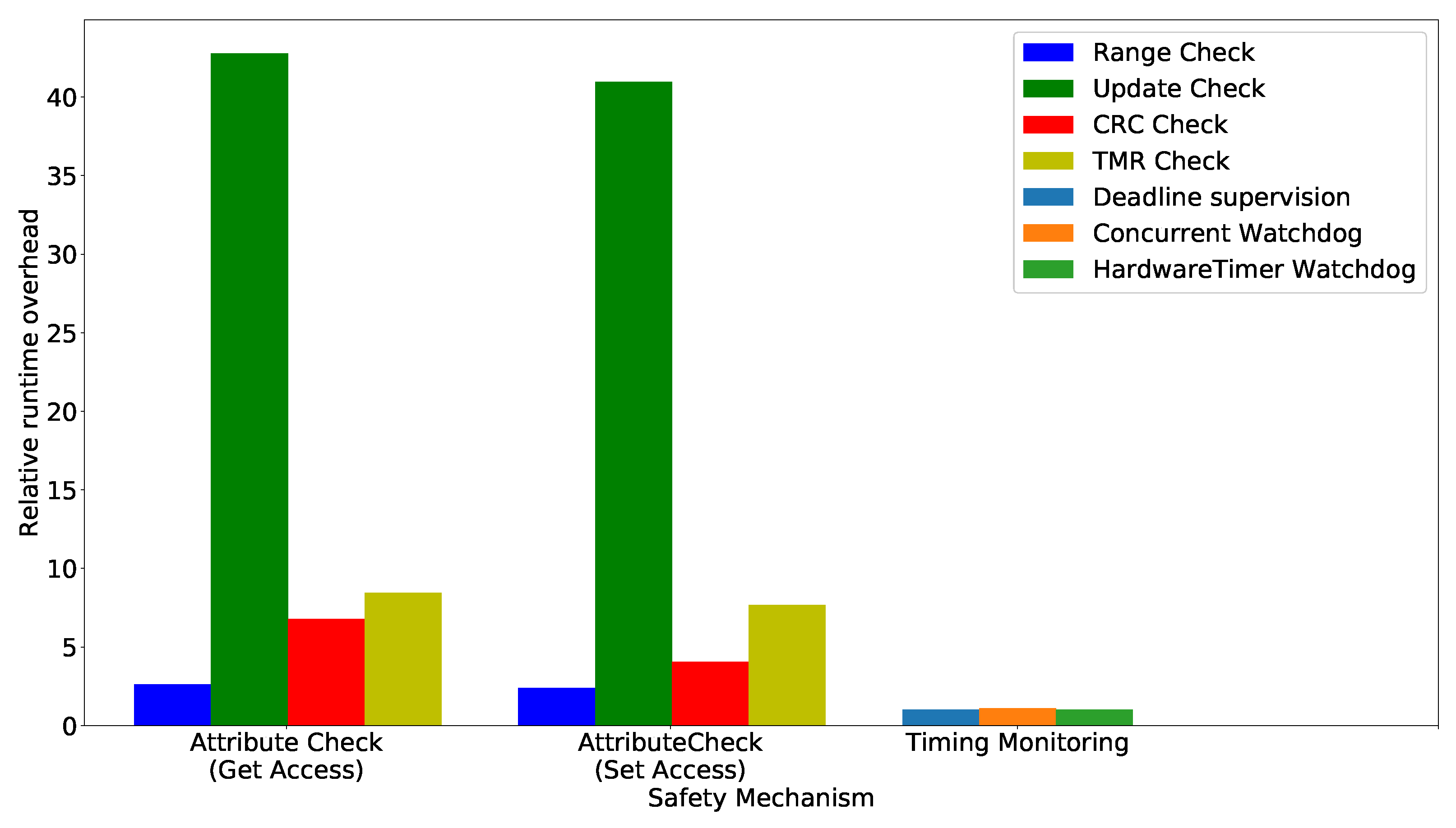
8.4. Evaluation of the Runtime Overhead

Safety-critical systems are often subject to timing constraints, i.e., a specific task has to finish within a certain time limit [67,68,69]. Thus, the runtime overhead of the generated safety mechanisms is important, as it may affect whether these timing constraints can be satisfied.
We measure the runtime overhead of the safety mechanisms by determining the system time at two distinct points and comparing this time to a baseline without the safety mechanisms. For the absolute runtime overhead, we calculate the difference between the measurement that includes the safety mechanism and the baseline. For the relative runtime overhead, we calculate the quotient of the measurement that includes the safety mechanism and the baseline.
For EDA, the baseline is a conventional getter-and-setter method. This is compared to a getter/setter method in which the safety mechanism is executed. For TCM, the baseline is the runtime of an unprotected operation, i.e., a for-loop that sums up the numbers from one to one million, which takes about 4.8 ms on the target evaluation platform. This is a typical runtime for operations in hard real-time systems, whose timing constraints are often in the range of single digit milliseconds (cf. [68,69]). This baseline is compared to the same method with the addition of the TCM mechanism being started at the beginning of the operation and being evaluated at the end of the operation. For voting, there exists no corresponding baseline, as it adds additional functionality to the system instead of only performing a transparent check. Thus, for voting only the absolute runtime overhead is measured for three input values. This corresponds to the use of a voter in a TMR scenario.
In order to reduce the influence of the target operating system scheduling, the baseline and protected methods are executed one million times and the time is measured before the first and right after the last execution. The runtime for a single execution is then obtained by dividing this measured value by the number of executions, i.e., one million. The process is repeated ten times and the displayed results are the arithmetic mean of these ten repetitions.

8.4.1. Results: Absolute Runtime Overhead

Table 1 shows the results for the absolute runtime overhead. For EDA, the runtime of accessing a protected attribute is higher than for modifying this attribute for each specific detection mechanism. The absolute overhead of each mechanism is below 1 μs, as the involved computations are relatively fast, e.g., a simple if-else statement for the range check. The update check incurs the highest absolute runtime overhead of the attribute error detection mechanisms. The reason for this is that the application program has to communicate with the operating system regarding the current system time. According to the results, this process is slower than the other types of checks, e.g., calculating a CRC checksum.
For TCM, the absolute runtime overhead for each evaluated mechanism is below 1 ms. The strictly sequential deadline supervision is an order of magnitude faster than the watchdog-based mechanisms. The reason for this is the additional amount of work executed at the beginning of the protected operation for the watchdog-based variants, e.g., creating and starting an operating system thread for the concurrent watchdog variant.
The absolute runtime overhead for the different voting mechanisms is below 1 μs. The runtime overhead for median voting is an order of magnitude higher than for majority and average voting. This is due to the multiple comparisons that are necessary to sort the underlying inputs according to their size.

8.4.2. Results: Relative Runtime Overhead

For EDA and TCM, Figure 18 shows the relative runtime overhead of these mechanisms. Recall that for voting no relative runtime overhead may be calculated as there exists no corresponding baseline.
The relative runtime overhead for EDA is relatively similar for accessing or modifying the protected attribute. If the protected attribute is accessed, the overhead is slightly larger (3.61 to 43.76 times larger than the baseline) than for modifying the protected attribute (3.39 to 40.96 times larger than the baseline). This is because the safety mechanism usually performs the actual error detection check when the protected attribute is accessed. Modifying the protected attribute, however, only updates mechanism-specific information.
Among the different error detection mechanisms that protect attributes, the Range check has the lowest relative runtime overhead. This check contains the least amount of added computational instructions, i.e., only two comparisons regarding the lower and upper bound when the protected attribute is accessed. TMR performs a larger number of comparisons, resulting in a larger relative runtime overhead. Compared to the other three mechanisms, the Update check is about 5 to 10 times slower than the other checks. As stated in Section 8.4.1, this is because it is the only check that has to communicate with the operating system.
For TCM, the relative overhead of the approaches ranges from 1% (deadline supervision) to 10% (concurrent watchdog). Note that the absolute runtime overhead of these mechanisms is independent of the actual content of the protected operation. Thus, the relative overhead becomes smaller in case the runtime of the baseline method increases. Conversely, in case the runtime of the baseline decreases, the relative overhead increases. The results presented in Figure 18, i.e., the overhead between 1% to 10%, has been calculated with a baseline operation whose runtime is around 4.8 ms.

8.4.3. Discussion of the Runtime Overhead

The absolute runtime overhead of each safety mechanism for a single protected element is one or more orders of magnitude less than 1 ms. In comparison, even hard real-time systems, e.g., an autonomous emergency braking system in an automobile, often only have timing constraints of several milliseconds [68,69]. Thus, as the safety mechanism voting is usually only applied to a select few system elements, the total impact of this safety mechanism on the timing behavior of the application is minimal.
In contrast to voting, the safety mechanisms error detection for attributes and timing constraint monitoring may be applied to a large number of system elements. While the application of these safety mechanisms to a single element still has a negligible impact on the timing behavior of the application, the total impact on the entire application depends upon how many system elements are protected by them.
For TCM, the impact on the timing behavior may be lessened by only protecting those operations whose timing constraints are greater than 1 ms. For such operations, the relative runtime overhead of the monitoring is less than 10% for operations that have a runtime that is typical for hard real-time systems. This relatively small overhead of the automatically generated safety mechanism is unlikely to require any additional design changes in the system. Nevertheless, it still needs to be taken into account for timing analysis approaches, e.g., [67,68,69].
For EDA, the overall impact on the timing behavior of the application depends on how often a protected attribute is accessed or modified by the application. This is influenced by the number of the protected attributes in the application and the individual frequency with which these are accessed or modified. Therefore, the overall impact on the timing behavior is application-dependent. A way to reduce this runtime overhead is to protect only those attributes that are truly safety-critical, e.g., as recommended by domain experts or by conducting fault-injections campaigns as described in [21,70].

9. Conclusions

This article provides an approach for the automatic code generation of safety mechanisms via MDD techniques. The inclusion of safety mechanisms in a safety-critical system is necessary to comply with safety standards, which in turn are often a requirement for market admission. The automatic generation of these mechanisms may increase developer productivity, decrease the number of bugs in the system and reduce the need to know the specific implementation details of each safety mechanism.
The article provides a structured way to formulate detailed safety requirements. These may be parsed automatically with the ANTLR framework and are subsequently used as the input for the generation process for software- and hardware-implemented safety mechanisms. For software-implemented safety mechanisms, this approach consists of modeling the safety mechanisms with UML stereotypes. Subsequently, model-to-model transformations realize these mechanisms in an intermediate model. For hardware-implemented safety mechanisms, the approach utilizes a GUI tool for the automatic initial configuration of these mechanisms in conjunction with a template-based code snippet repository.
We measured the runtime of the employed model transformation steps. They scale linearly with the number of safety mechanisms that are generated. The total runtime of these transformations, even for a large number of safety mechanisms, does not negatively impact the workflow of a developer.
Furthermore, we evaluated the memory and runtime overhead of the generated safety mechanisms on a target platform. According to our measurements, both types of overhead are negligibly small if only a single safety mechanism for a single protected element is considered. However, depending on the specific safety mechanism, the relative overhead may exceed 100% overhead. Thus, the application of safety mechanisms should be limited to only those elements that are strictly safety-critical in order to reduce memory usage and improve the runtime of the system.
For future work, a MDD generation approach for more software-implemented safety mechanisms, e.g., rollback recovery, may be proposed. Another research avenue is to provide SysML [71] model representation of the initial hardware and pin configuration, thereby eliminating the need for a custom GUI for the generation of hardware-implemented safety mechanisms. Moreover, the key concept to generate a non-functional property like safety via MDD techniques could be applied to other non-functional properties, e.g., energy.

Author Contributions

Conceptualization, L.H.; methodology, L.H.; software, L.H.; validation, L.H.; investigation, L.H.; writing—original draft preparation, L.H.; writing—review and editing, L.H. and E.P.; visualization, L.H.; supervision, E.P.; funding acquisition, E.P. All authors have read and agreed to the published version of the manuscript.

Funding

This work was partially funded by the German Federal Ministry of Economics and Technology (Bundesministerium fuer Wirtschaft und Technologie-BMWi) within the project “Holistic model-driven development for embedded systems in consideration of diverse hardware architectures” (HolMES). The grant id is ZF4447201BZ7.

Acknowledgments

The authors would like to thank Felix Häusler for software development assistance. We acknowledge support by Deutsche Forschungsgemeinschaft (DFG) and Open Access Publishing Fund of Osnabrück University.

Conflicts of Interest

The authors declare no conflict of interest. The funders had no role in the design of the study; in the collection, analyses, or interpretation of data; in the writing of the manuscript, or in the decision to publish the results.

References

  1. Storey, N. Safety-Critical Computer System; Addison-Wesley: Harlow, UK, 1996. [Google Scholar]
  2. Johnston, P.; Harris, R. The Boeing 737 MAX Saga: Lessons for Software Organizations. Softw. Qual. Prof. Mag. 2019, 21, 4–12. [Google Scholar]
  3. Neumann, P.G. Computer Related Risks; ACM Press/Addison-Wesley Publishing Co.: New York, NY, USA, 1995. [Google Scholar]
  4. International Electrotechnical Commission. Medical Device Software—Software Life-Cycle Processes: IEC 62304; International Electrotechnical Commission: Geneva, Switzerland, 2011. [Google Scholar]
  5. Radio Technical Commission for Aeronautics; European Organization for Civil Aviation Equipment. Software Considerations in Airborne Systems and Equipment Certification: DO-178; Radio Technical Commission for Aeronautics: Washington, DC, USA, 2006. [Google Scholar]
  6. International Organization for Standardization. ISO 26262 Road Vehicles—Functional Safety, 2nd ed.; ISO: Geneva, Switzerland, 2018. [Google Scholar]
  7. International Electrotechnical Commission. IEC 61508 Edition 2.0. Functional Safety for Electrical/Electronic/Programmable Electronic Safety-Related Systems; International Electrotechnical Commission: Geneva, Switzerland, 2010. [Google Scholar]
  8. IBM. Rational Rhapsody Developer. 2021. Available online: https://www.ibm.com/us-en/marketplace/uml-tools (accessed on 12 October 2021).
  9. The Eclipse Foundation. Eclipse Papyrus Modeling Environment. 2021. Available online: https://www.eclipse.org/papyrus (accessed on 12 October 2021).
  10. Huning, L.; Osterkamp, T.; Schaarschmidt, M.; Pulvermüller, E. Seamless Integration of Hardware Interfaces in UML-based MDSE Tools. In Proceedings of the 16th International Conference on Software Technologies, ICSOFT 2021, Online Streaming, 6–8 July 2021; Fill, H., van Sinderen, M., Maciaszek, L.A., Eds.; 2021; pp. 233–244. [Google Scholar] [CrossRef]
  11. Bunse, C.; Gross, H.G.; Peper, C. Applying a Model-based Approach for Embedded System Development. In Proceedings of the 33rd EUROMICRO Conference on Software Engineering and Advanced Applications (EUROMICRO 2007), Lubeck, Germany, 28–31 August 2007; pp. 121–128. [Google Scholar] [CrossRef] [Green Version]
  12. Karsai, G.; Sztipanovits, J.; Ledeczi, A.; Bapty, T. Model-integrated development of embedded software. Proc. IEEE 2003, 91, 145–164. [Google Scholar] [CrossRef] [Green Version]
  13. Hatcliff, J.; Wassyng, A.; Kelly, T.; Comar, C.; Jones, P. Certifiably Safe Software-dependent Systems: Challenges and Directions. In Proceedings of the Conference on The Future of Software Engineering (FOSE 2014), Hyderabad, India, 31 May–7 June 2014; ACM: New York, NY, USA, 2014; pp. 182–200. [Google Scholar] [CrossRef]
  14. Cleland-Huang, J.; Rahimi, M. A Case Study: Injecting Safety-Critical Thinking into Graduate Software Engineering Projects. In Proceedings of the 2017 IEEE/ACM 39th International Conference on Software Engineering: Software Engineering Education and Training Track (ICSE-SEET), Buenos Aires, Argentina, 20–28 May 2017; pp. 67–76. [Google Scholar]
  15. Huning, L.; Iyenghar, P.; Pulvermueller, E. UML Specification and Transformation of Safety Features for Memory Protection. In Proceedings of the 14th International Conference on Evaluation of Novel Approaches to Software Engineering, Heraklion, Greece, 4–5 May 2019; pp. 281–288. [Google Scholar]
  16. Huning, L.; Iyenghar, P.; Pulvermueller, E. A UML Profile for Automatic Code Generation of Optimistic Graceful Degradation Features at the Application Level. In Proceedings of the 8th International Conference on Model-Driven Engineering and Software Development—Volume 1: MODELSWARD, Valetta, Malta, 25–27 February 2020; pp. 336–343. [Google Scholar] [CrossRef]
  17. Huning, L.; Iyenghar, P.; Pulvermueller, E. A Workflow for Automatically Generating Application-level Safety Mechanisms from UML Stereotype Model Representations. In Proceedings of the 15th International Conference on Evaluation of Novel Approaches to Software Engineering—Volume 1: ENASE, Online Streaming, 5–6 May 2020; pp. 216–228. [Google Scholar] [CrossRef]
  18. Huning, L.; Iyenghar, P.; Pulvermüller, E. A Workflow for Automatic Code Generation of Safety Mechanisms via Model-Driven Development. In Evaluation of Novel Approaches to Software Engineering; Ali, R., Kaindl, H., Maciaszek, L.A., Eds.; Springer International Publishing: Cham, Switzerland, 2021; pp. 420–443. [Google Scholar]
  19. Huning, L.; Iyenghar, P.; Pulvermueller, E. UML-based Model-Driven Code Generation of Error Detection Mechanisms. In Proceedings of the 15th International Conference on Software Engineering Advances, Porto, Portugal, 18–22 October 2020; pp. 98–105. [Google Scholar]
  20. Jouault, F.; Allilaire, F.; Bezivin, J.; Kurtev, I. ATL: A model transformation tool. Sci. Comput. Program. 2006, 72, 31–39. [Google Scholar] [CrossRef]
  21. Borchert, C.; Schirmeier, H.; Spinczyk, O. Generative Software-based Memory Error Detection and Correction for Operating System Data Structures. In Proceedings of the 2013 43rd Annual IEEE/IFIP International Conference on Dependable Systems and Networks (DSN), Washington, DC, USA, 24–27 June 2013; pp. 1–12. [Google Scholar] [CrossRef] [Green Version]
  22. Trindade, R.; Bulwahn, L.; Ainhauser, C. Automatically Generated Safety Mechanisms from Semi-Formal Software Safety Requirements. In Computer Safety, Reliability, and Security; Bondavalli, A., Di Giandomenico, F., Eds.; Springer International Publishing: Cham, Switzerland, 2014; pp. 278–293. [Google Scholar]
  23. Hu, T.; Bertolott, I.C.; Navet, N. Towards seamless integration of N-version programming in model-based design. In Proceedings of the 2017 22nd IEEE International Conference on Emerging Technologies and Factory Automation (ETFA), Limassol, Cyprus, 12–15 September 2017; pp. 1–8. [Google Scholar] [CrossRef] [Green Version]
  24. Mader, R.; Grießnig, G.; Armengaud, E.; Leitner, A.; Kreiner, C.; Bourrouilh, Q.; Steger, C.; Weiß, R. A Bridge from System to Software Development for Safety-Critical Automotive Embedded Systems. In Proceedings of the 2012 38th Euromicro Conference on Software Engineering and Advanced Applications, Izmir, Turkey, 5–8 September 2012; pp. 75–79. [Google Scholar] [CrossRef]
  25. Pezzé, M.; Wuttke, J. Model-driven generation of runtime checks for system properties. Int. J. Softw. Tools Technol. Transf. 2016, 18, 1–19. [Google Scholar] [CrossRef]
  26. Wang, K.; Shen, W. Runtime Checking of UML Association-Related Constraints. In Proceedings of the 5th International Workshop on Dynamic Analysis, Minneapolis, MN, USA, 20–26 May 2007; p. 3. [Google Scholar] [CrossRef]
  27. Hein, C.; Ritter, T.; Wagner, M. System monitoring using constraint checking as part of model based system management. In Models in Software Engineering; Springer Berlin Heidelberg: Berlin/Heidelberg, Germany, 2008; pp. 206–211. [Google Scholar]
  28. Richters, M.; Gogolla, M. Aspect-Oriented Monitoring of UML and OCL Constraints. Available online: https://www.researchgate.net/publication/2908480_Aspect-Oriented_Monitoring_of_UML_and_OCL_Constraints (accessed on 12 October 2021).
  29. Rosenblum, D.S. A Practical Approach to Programming with Assertions. IEEE Trans. Softw. Eng. 1995, 21, 19–31. [Google Scholar] [CrossRef]
  30. Jeffrey, M.V.; Keith, W.M. Putting assertions in their place. In Proceedings of the 1994 IEEE International Symposium on Software Reliability Engineering, Monterey, CA, USA, 6–9 November 1994; pp. 152–157. [Google Scholar] [CrossRef]
  31. Tanzi, T.J.; Textoris, R.; Apvrille, L. Safety properties modelling. In Proceedings of the 2014 7th International Conference on Human System Interactions (HSI), Lisbon, Portugal, 16–18 June 2014; pp. 198–202. [Google Scholar] [CrossRef]
  32. Beckers, K.; Côté, I.; Frese, T.; Hatebur, D.; Heisel, M. Systematic Derivation of Functional Safety Requirements for Automotive Systems. In Computer Safety, Reliability, and Security; Bondavalli, A., Di Giandomenico, F., Eds.; Springer International Publishing: Cham, Switzerland, 2014; pp. 65–80. [Google Scholar]
  33. Yakymets, N.; Perin, M.; Lanusse, A. Model-driven multi-level safety analysis of critical systems. In Proceedings of the 9th Annual IEEE International Systems Conference, Vancouver, BC, Canada, 13–16 April 2015; pp. 570–577. [Google Scholar] [CrossRef] [Green Version]
  34. Kan, S.; Huang, Z. Detecting safety-related components in statecharts through traceability and model slicing. Softw. Pract. Exp. 2018, 48, 428–448. [Google Scholar] [CrossRef]
  35. Elektrobit. EB Tresos Safety. 2021. Available online: https://www.elektrobit.com/products/ecu/eb-tresos/functional-safety (accessed on 12 October 2021).
  36. Vector. PrEEVision. 2021. Available online: https://www.vector.com/int/en/products/products-a-z/software/preevision/ (accessed on 12 October 2021).
  37. SAFEADAPT EU-Project (2013–2017). Safe Adaptive Software for Fully Electric Vehicles. 2017. Available online: www.safeadapt.eu (accessed on 12 October 2021).
  38. Penha, D.; Weiss, G.; Stante, A. Pattern-Based Approach for Designing Fail-Operational Safety-Critical Embedded Systems. In Proceedings of the 2015 IEEE 13th International Conference on Embedded and Ubiquitous Computing, Porto, Portugal, 21–23 October 2015; pp. 52–59. [Google Scholar] [CrossRef]
  39. Weiss, G.; Schleiss, P.; Drabek, C. Towards Flexible and Dependable E/E-Architectures for Future Vehicles. In Proceedings of the 4th International Workshop on Critical Automotive Applications: Robustness & Safety (CARS 2016), Göteborg, Sweden, 6 September 2016. [Google Scholar]
  40. Ruiz, A.; Juez, G.; Schleiss, P.; Weiss, G. A safe generic adaptation mechanism for smart cars. In Proceedings of the 2015 IEEE 26th International Symposium on Software Reliability Engineering (ISSRE), Gaithersbury, MD, USA, 2–5 November 2015; pp. 161–171. [Google Scholar] [CrossRef]
  41. SAFURE EU-Project (2015–2018). Safety and Security by Design for Interconnected Mixed-Critical Cyber-Physical Systems. 2018. Available online: https://cordis.europa.eu/project/id/644080 (accessed on 12 October 2021).
  42. Moestl, M.; Thiele, D.; Ernst, R. Invited: Towards fail-operational Ethernet based in-vehicle networks. In Proceedings of the 2016 53nd ACM/EDAC/IEEE Design Automation Conference (DAC), Austin, TX, USA, 5–9 June 2016; pp. 1–6. [Google Scholar] [CrossRef] [Green Version]
  43. Thiele, D.; Ernst, R.; Diemer, J. Formal Worst-Case Timing Analysis of Ethernet TSN’s Time-Aware and Peristaltic Shapers. In Proceedings of the IEEE Vehicular Networking Conference (VNC), Kyoto, Japan, 16–18 December 2016; pp. 251–258. [Google Scholar] [CrossRef]
  44. Thiele, D.; Ernst, R. Formal analysis based evaluation of software defined networking for time-sensitive Ethernet. In Proceedings of the 2016 Design, Automation & Test in Europe Conference & Exhibition (DATE), Dresden, Germany, 5–9 June 2016; pp. 31–36. [Google Scholar] [CrossRef]
  45. Fernandez, G.; Abella, J.; Quinones, E.; Fossati, L.; Zulianello, M.; Vardanega, T.; Cazorla, F.J. Seeking Time-Composable Partitions of Tasks for COTS Multicore Processors. In Proceedings of the 2015 IEEE 18th International Symposium on Real-Time Distributed Computing, Auckland, New Zealand, 13–17 April 2015; pp. 208–217. [Google Scholar] [CrossRef] [Green Version]
  46. Girbal, S.; Jean, X.; Le Rhun, J.; Pérez, D.G.; Gatti, M. Deterministic platform software for hard real-time systems using multi-core COTS. In Proceedings of the 2015 IEEE/AIAA 34th Digital Avionics Systems Conference (DASC), Prague, Czech Republic, 13–17 September 2015; pp. 8D4-1–8D4-15. [Google Scholar] [CrossRef] [Green Version]
  47. Fernandez, G.; Jalle, J.; Abella, J.; Quinones, E.; Vardanega, T.; Cazorla, F.J. Computing Safe Contention Bounds for Multicore Resources with Round-Robin and FIFO Arbitration. IEEE Trans. Comput. 2016. [Google Scholar] [CrossRef] [Green Version]
  48. Antonino, P.O.; Keuler, T.; Nakagawa, E.Y. Towards an approach to represent safety patterns. In Proceedings of the Seventh International Conference on Software Engineering Advances, Lisbon, Portugal, 18–23 November 2012; pp. 228–237. [Google Scholar]
  49. Subasi, O.; Unsal, O.; Labarta, J.; Yalcin, G.; Cristal, A. CRC-Based Memory Reliability for Task-Parallel HPC Applications. In Proceedings of the 2016 IEEE International Parallel and Distributed Processing Symposium (IPDPS), Chicago, IL, USA, 23–27 May 2016; pp. 1101–1112. [Google Scholar] [CrossRef]
  50. Pattabiraman, K.; Grover, V.; Zorn, B.G. Samurai: Protecting Critical Data in Unsafe Languages. In Proceedings of the 3rd ACM SIGOPS/EuroSys European Conference on Computer Systems 2008, Glasgow, UK, 1–4 April 2008; pp. 219–232. [Google Scholar] [CrossRef]
  51. Chen, D.; Messer, A.; Bernadat, P.; Fu, G.; Dimitrijevic, Z.; Lie, D.J.F.; Mannaru, D.; Riska, A.; Milojicic, D. JVM Susceptibility to Memory Errors. In Proceedings of the 2001 Symposium on JavaTM Virtual Machine Research and Technology Symposium, Monterey, CA, USA, 23–24 April 2001; pp. 67–78. [Google Scholar]
  52. Arora, A.; Kulkarni, S. Detectors and Correctors: A Theory of Fault-Tolerance Components. In Proceedings of the 18th International Conference on Distributed Computing Systems ICDCS’98, Amsterdam, The Netherlands, 26–29 May 1998; pp. 436–443. [Google Scholar] [CrossRef]
  53. Arora, A.; Kulkarni, S. Component Based Design of Multitolerant Systems. IEEE Trans. Softw. Eng. 1998, 24, 63–78. [Google Scholar] [CrossRef]
  54. Lin, Y.; Kulkarni, S.; Jhumka, A. Automation of fault-tolerant graceful degradation. Distrib. Comput. 2019, 32, 1–25. [Google Scholar] [CrossRef] [Green Version]
  55. Chen, J.; Kulkarni, S. MR4UM: A Framework for Adding Fault Tolerance to UML State Diagrams. Theor. Comput. Sci. 2013, 496, 17–33. [Google Scholar] [CrossRef]
  56. Noyer, A.; Iyenghar, P.; Engelhardt, J.; Pulvermueller, E.; Bikker, G. A model-based framework encompassing a complete workflow from specification until validation of timing requirements in embedded software systems. Softw. Qual. J. 2016, 25, 671–701. [Google Scholar] [CrossRef]
  57. Iyenghar, P.; Wessels, S.; Noyer, A.; Pulvermueller, E. Model-based tool support for energy-aware scheduling. In Proceedings of the Forum on Specification and Design Languages, Bremen, Germany, 14–16 September 2016. [Google Scholar]
  58. Iyenghar, P.; Pulvermueller, E. A Model-Driven Workflow for Energy-Aware Scheduling Analysis of IoT-Enabled Use Cases. IEEE Internet Things J. 2018, 5, 4914–4925. [Google Scholar] [CrossRef]
  59. O’Shea, D.; Ortin, F.; Geary, K. A virtualized test automation framework: A DellEMC case study of test automation practice. Softw. Pract. Exp. 2018, 49, 329–337. [Google Scholar] [CrossRef]
  60. Nooraei Abadeh, M.; Ajoudanian, S. A model-driven framework to enhance the consistency of logical integrity constraints: Introducing integrity regression testing. Softw. Pract. Exp. 2019, 49, 274–300. [Google Scholar] [CrossRef]
  61. Uzun, B.; Tekinerdogan, B. Architecture conformance analysis using model-based testing: A case study approach. Softw. Pract. Exp. 2019, 49, 423–448. [Google Scholar] [CrossRef]
  62. Robinson, R.M.; Anderson, K.J. SIL Rating Fire Protection Equipment. In Proceedings of the 8th Australian Workshop on Safety Critical Systems and Software—Volume 33, Canberra, Australia, 1 October 2003; pp. 89–97. [Google Scholar]
  63. Kim, S.; Kim, Y. A case study on an evaluation procedure of hardware SIL for fire detection system. Int. J. Appl. Eng. Res. 2017, 12, 359–364. [Google Scholar]
  64. Parr, T. ANTLR. 2021. Available online: https://www.antlr.org/index.html (accessed on 12 October 2021).
  65. Armoush, A. Design Patterns for Safety-Critical Embedded Systems. Ph.D. Thesis, RWTH Aachen University, Aachen, Germany, 2010. [Google Scholar]
  66. Kolovos, D.; Rose, L.; Garcia-Dominguez, A.; Paige, R. The Epsilon Book. Available online: https://www.eclipse.org/epsilon/doc/book/ (accessed on 12 October 2021).
  67. Iyenghar, P.; Huning, L.; Pulvermueller, E. Early Synthesis of Timing Models in AUTOSAR-based Automotive Embedded Software Systems. In Proceedings of the 8th International Conference on Model-Driven Engineering and Software Development—Volume 1: MODELSWARD, Valetta, Malta, 25–27 February 2020; pp. 26–38. [Google Scholar] [CrossRef]
  68. Iyenghar, P.; Huning, L.; Pulvermueller, E. Automated End-to-End Timing Analysis of AUTOSAR-based Causal Event Chains. In Proceedings of the 15th International Conference on Evaluation of Novel Approaches to Software Engineering—Volume 1: ENASE, Online Streaming, 5–6 May 2020; pp. 477–489. [Google Scholar] [CrossRef]
  69. Iyenghar, P.; Huning, L.; Pulvermueller, E. Model-Based Timing Analysis of Automotive Use Case Developed in UML. In Evaluation of Novel Approaches to Software Engineering; Ali, R., Kaindl, H., Maciaszek, L.A., Eds.; Springer International Publishing: Cham, Switzerland, 2021; pp. 360–385. [Google Scholar]
  70. Borchert, C.; Schirmeier, H.; Spinczyk, O. Generic soft-error detection and correction for concurrent data structures. IEEE Trans. Dependable Secur. Comput. 2017, 14, 22–36. [Google Scholar] [CrossRef] [Green Version]
  71. Object Management Group. OMG Systems Modeling Language Version 1.6; Technical Report; Object Management Group: Needham, MA, USA, 2019. [Google Scholar]
Figure 1. Workflow for the model-driven code generation of safety mechanisms (Unified Modeling Language (UML) 2.5 activity diagram notation).
Electronics 10 03150 g001
Figure 2. Functional model of the fire detection application (screenshot of a IBM Rhapsody class diagram).
Electronics 10 03150 g002
Figure 3. Derived safety requirements for the application example.
Electronics 10 03150 g003
Figure 4. Model of the fire detection application with safety stereotypes applied (screenshot of a IBM Rhapsody class diagram). Classes that do not contain a safety mechanism according to the requirements presented in Section 4.2.2 have been omitted.
Electronics 10 03150 g004
Figure 5. Intermediate model of the application example after model-to-model transformations (screenshot of an IBM Rhapsody class diagram). Classes that do not contain a safety mechanism according to the requirements presented in Section 4.2.2 have been omitted. For legibility, only selected attributes, operations, and template parameters of the classes that realize safety mechanisms, i.e., DeadlineSupervision, Voter, and ProtectedAttribute, are shown.
Electronics 10 03150 g005
Figure 6. Screenshot of the PinConfig tool with the configuration for the fire detection application example. Note that there exist different pin numbering systems for the Raspberry Pi. The middle compartment uses the physical layout for pin numbering, while the left and right compartments use the BCM (Broadcom) format.
Electronics 10 03150 g006
Figure 7. Screenshot of the prototype for automatically applying safety stereotypes to the application model.
Electronics 10 03150 g007
Figure 8. Runtime behavior of the error handling process (UML 2.5 activity diagram notation).
Electronics 10 03150 g008
Figure 9. Integration of profiles describing safety mechanisms (UML 2.5 profile diagram notation).
Electronics 10 03150 g009
Figure 10. The SafetyGenBasic profile (UML 2.5 profile diagram notation).
Electronics 10 03150 g010
Figure 11. Integration of software-implemented safety mechanisms in an existing software architecture (UML 2.5 class diagram notation).
Electronics 10 03150 g011
Figure 12. Integration of software-implemented safety mechanisms in an existing software architecture (UML 2.5 notation).
Electronics 10 03150 g012
Figure 13. Overview of the source code artifacts involved with the generation process of the PinConfig tool (UML 2.5 notation with additional non-UML symbols for representing files at the bottom).
Electronics 10 03150 g013
Figure 14. Runtime for parsing safety requirements and applying the corresponding model representation of the safety mechanism.
Electronics 10 03150 g014
Figure 15. Runtime for generating software- and hardware-implemented safety mechanisms. Note that the measurements for hardware-implemented safety mechanisms have only been conducted for a smaller number of generated elements than software-implemented safety mechanisms, due to the necessity of a corresponding number of physical hardware interfaces being available on the studied microcontroller.
Electronics 10 03150 g015
Figure 16. Absolute memory overhead of the generated safety mechanisms in bytes.
Electronics 10 03150 g016
Figure 17. Relative memory usage of error detection for attributes. A value of 1 is used as the baseline, i.e., no memory overhead. A value of 2 means a 100% memory overhead compared to the baseline.
Electronics 10 03150 g017
Figure 18. Relative runtime overhead for the error detection for attributes and timing constraint monitoring. A value of 1 is used as the baseline, i.e., no runtime overhead. A value of 2 means a 100% runtime overhead compared to the baseline.
Electronics 10 03150 g018
Table 1. Absolute runtime overhead of the generated safety mechanisms.
Safety MechanismTime (s)Safety MechanismTime (s)
Range Check (access) 4.45 10 8 Range Check (modify) 4.41 10 8
Update Check (access) 7.39 10 7 Update Check (modify) 7.35 10 7
CRC Check (access) 1.17 10 7 CRC Check (modify) 7.52 10 8
TMR Check (access) 1.45 10 7 TMR Check (modify) 1.41 10 7
Deadline Supervision 4.71 10 5 Majority Voting 1.30 10 7
Concurrent Watchdog 4.45 10 4 Median Voting 1.22 10 6
HWTimer Watchdog 1.21 10 4 Average Voting 1.00 10 7
Publisher’s Note: MDPI stays neutral with regard to jurisdictional claims in published maps and institutional affiliations.

