Article

Double Overt-Leaf Shaped CPW-Fed Four Port UWB MIMO Antenna

1
Department of Electrical, Electronic and Information Technology, DEI-“Guglielmo Marconi”, Università di Bologna, 40136 Bologna, Italy
2
Department of Information Engineering, Electronics and Telecommunications, Sapienza Università di Roma, 00184 Rome, Italy
3
Telecommunication Engineering Department, University of Engineering & Technology, Mardan 23200, Pakistan
4
Department of Electrical Engineering, College of Engineering, King Saud University, Riyadh 11421, Saudi Arabia
5
Department of Information Engineering and Computer Science, University of Trento, 38100 Trento, Italy
*
Authors to whom correspondence should be addressed.
Electronics 2021, 10(24), 3140; https://doi.org/10.3390/electronics10243140
Submission received: 17 October 2021 / Revised: 9 December 2021 / Accepted: 13 December 2021 / Published: 17 December 2021
(This article belongs to the Section Microwave and Wireless Communications)

Abstract

:
This paper presents a 4 × 4 multi-input multi-output antenna array for ultra-wideband applications. The single element of the array is comprised of a modified co-planar waveguide-fed double overt-leaf shaped patch radiator. The co-planar ground is optimized to achieve maximum impedance matching in the operating frequency band. The results show that the single antenna element offers an impedance bandwidth of 13.2 GHz starting from 3.2 GHz to 16.7 GHz. It is also observed from the results that the antenna offers good radiation characteristics and acceptable gain for the frequency band of interest. Furthermore, a 4 × 4 MIMO array is designed by utilizing the polarization diversity technique. To improve the isolation performance among antenna elements, a fan-shaped decoupler is introduced on the other side of the substrate, which ensures minimum isolation of 20 dB. Moreover, the proposed MIMO array operates in the frequency range of 2.75–16.05 GHz. The proposed MIMO array is fabricated and measured for the validation of simulation results, and it is observed that both the results are well in agreement.

1. Introduction

Recent advancements in wireless communication require a system that is capable of exchanging a huge amount of information with a high data rate, higher capacity, reliability, and security with less complexity. These demands can be fulfilled by utilizing ultra-wideband (UWB) technology. UWB technology is a potential candidate for many wireless communication systems as it provides a high data rate by using a low-cost infrastructure. However, the conventional UWB technology encounters multipath propagation challenges. For this purpose, multiple-input multiple-output (MIMO) technology has been evolved as a major research area in the past few years. The research has proved that the MIMO antenna system is capable of fulfilling the requirements of the UWB systems. Designing such an antenna is quite a challenging task as multiple antenna system adds a few more performance parameters to look upon. The mutual coupling (isolation) between the antenna elements is one of the key performance parameters, which should be as minimum as possible to avoid channel capacity loss.
To improve isolation between MIMO antenna elements, several antenna configurations have been reported in the literature. The coupling between the antenna elements has been improved by using stubs between the patch radiators [1,2,3,4,5,6,7,8], electromagnetic bandgap (EBG) structures [9,10,11,12], frequency selective surface (FSS) [13], neutralization lines with the radiator and the ground plane [14,15,16,17,18], defected ground structure (DGS) [19,20,21], decoupling structures [22,23], and slotted edge substrate [24], etc. These techniques have demonstrated satisfactory results in minimizing the coupling effects between the antenna elements; however, this also needs to be highlighted that the antenna designs reported above have either lower bandwidth, large size, or not-so-good isolation (≤20 dB). In addition, the designs presented above are either complex in nature or composed of complicated decoupling structures.
In this paper, a compact 4 × 4 modified CPW-fed double overt-leaf shaped MIMO antenna array is designed for UWB applications. Wide impedance bandwidth is achieved by optimizing the ground plane as well as the radiating patch. For reduced isolation between the array elements, a quadrature-phase arrangement is adopted, which corresponds to the polarization diversity configuration. Furthermore, a fan-shaped decoupler is introduced at the backside of the substrate to further improve the isolation between the array elements. From the presented configuration, it is observed that the designed array operates in the frequency range of 2.75–16.05 GHz and provides >20 dB isolation between array elements. The article is arranged as follows: Single antenna element designing and simulation results are discussed in Section 2 followed by MIMO configuration and corresponding results in Section 3. The performance of the proposed array in terms of envelope correlation coefficient (ECC), diversity gain (DG), and mean effective gain (MEG) is discussed in Section 4. The article concludes in Section 5.

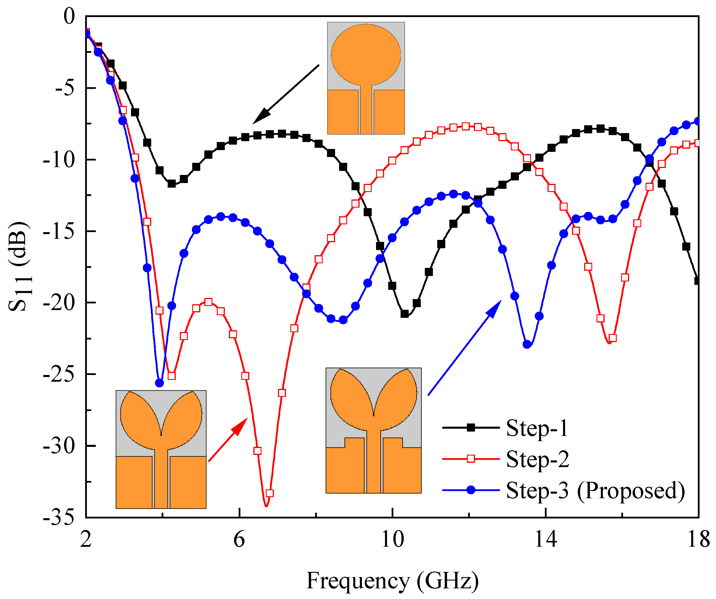
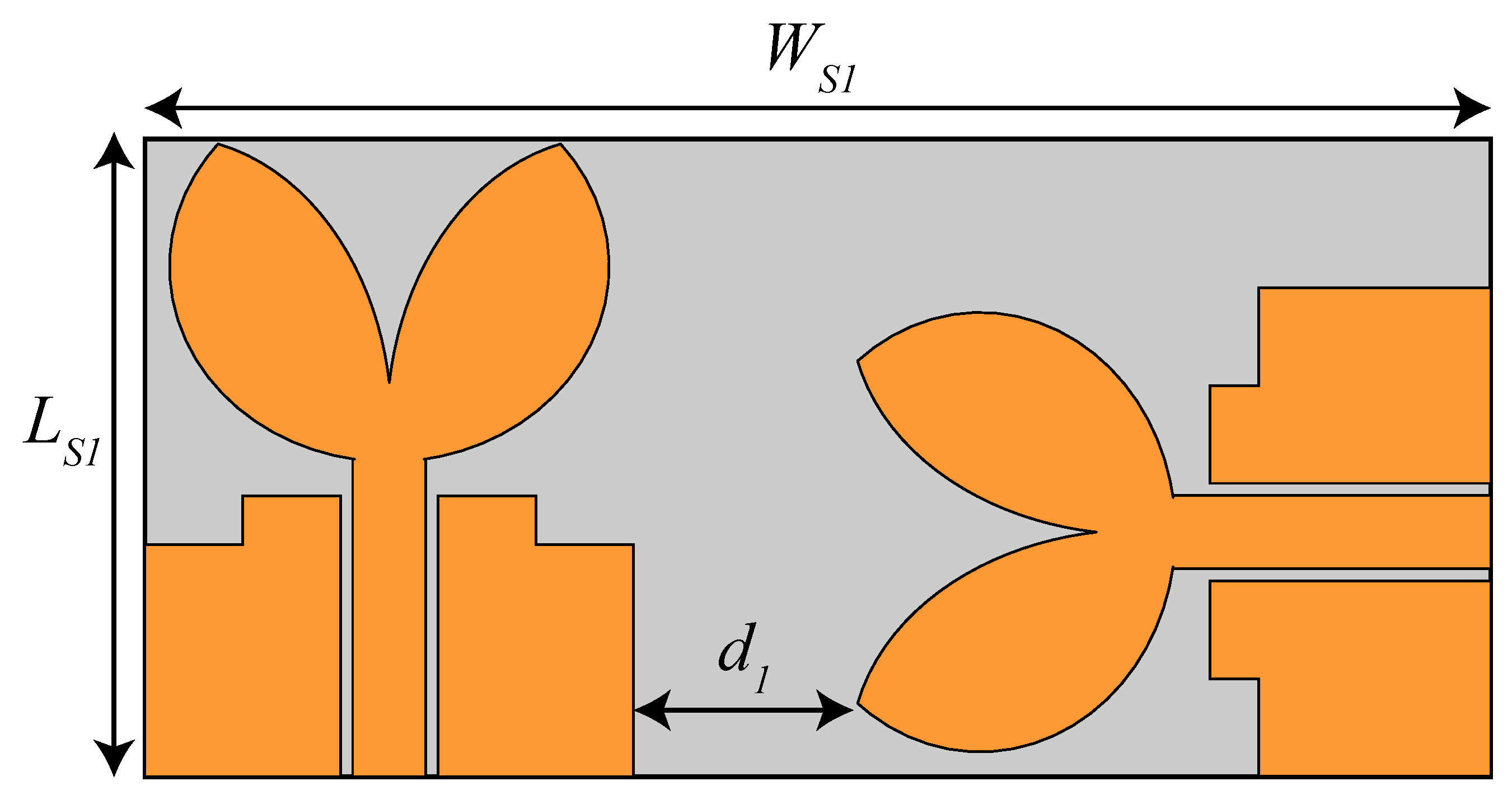
2. Single Element Design

Figure 1 shows the schematic of the proposed CPW-fed UWB antenna with all the design parameters. The optimized values of all the design parameters are listed in Table 1. From the figure, it can be noted that the proposed antenna design is composed of a co-planar waveguide (CPW)-fed double overt-leaf shaped radiating structure. The CPW feed technique is used due to its several advantages, e.g., low losses, co-planar nature, and ease of fabrication, etc. The proposed antenna is designed on a low-cost 1.6 mm thick FR-4 substrate having ε r = 4.3 and tanδ = 0.025.
The construction of the proposed antenna starts with the design of a conventional CPW-fed elliptical monopole as shown in the inset of Figure 2 along with its respective reflection coefficient ( S 11 ) response. It is observed that the CPW-fed elliptical monopole antenna offers a response in the frequency range of 8.56–13.78 GHz. To improve the impedance bandwidth in the UWB frequency band, two ellipses are etched from the conventional design, which results in an overt-leaf-shaped patch radiator (shown in the inset of Figure 2). This modification tends to achieve dual-band response in the frequency range of 3.2–10 GHz and 13.5–17 GHz as shown in Figure 2. To further improve the impedance bandwidth, a modified ground plane (see inset of Figure 2) is used. The modification in the ground plane reduces the inductive effect of the patch radiator by initiating a capacitive effect, which results in a purely resistive impedance [25]. This helps to achieve an impedance bandwidth of 13.5 GHz in the frequency range of 3.2–16.7 GHz.

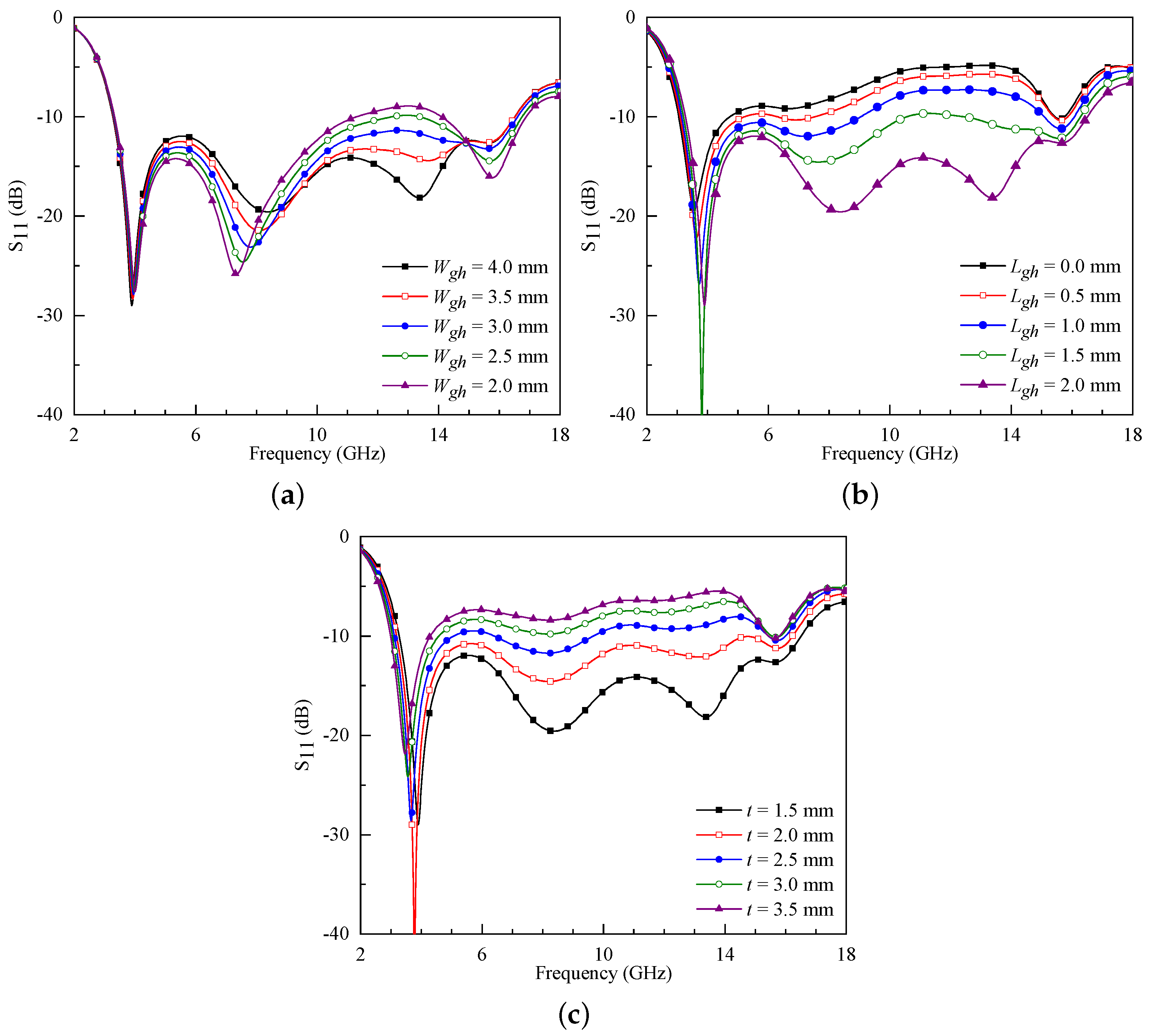
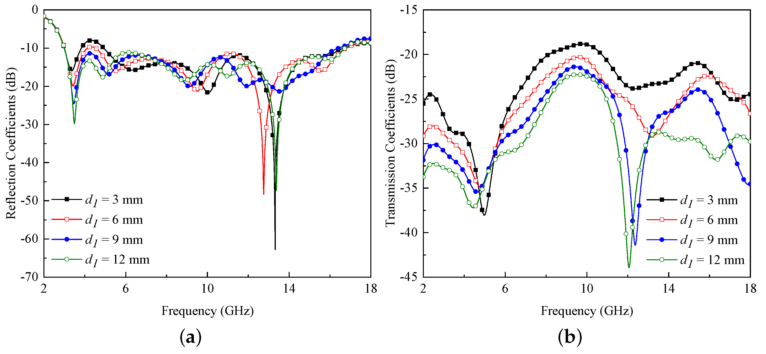
2.1. Parametric Study

To assess antenna’s performance for different design variables, a parametric study is conducted with three most vital parameters namely W g h , L g h , and t. The results of antenna performance for different values of these parameters are displayed in Figure 3a–c.
Figure 3a shows S 11 results with variation in W g h (keeping all other parameters similar to Table 1), the horizontal length of the region etched from the ground plane. It can be observed from the results that impedance matching of the antenna improves with an increasing value of W g h . Similarly, in Figure 3b, performance variation is displayed with varying L g h (keeping all other parameters similar to Table 1), the vertical depth of the region etched from the ground plane. From the results, it is evident that the antenna has only one resonant band at ∼4 GHz when L g h < 1.5 mm. For L g h > 1.5 mm, due to the occurrence of multiple resonances, UWB response is obtained.
The distance between the ground plane and the radiator, named as t, also plays a vital role in achieving impedance matching. When the gap between the patch and the ground plane is >2 mm, the antenna resonates only around 4 GHz. The optimum UWB response is achieved for t = 1.5 mm as shown in Figure 3c. From the above-presented results, it can be noted that the parameters L g h , W g h , and t are playing a crucial role in achieving wide impedance bandwidth performance.

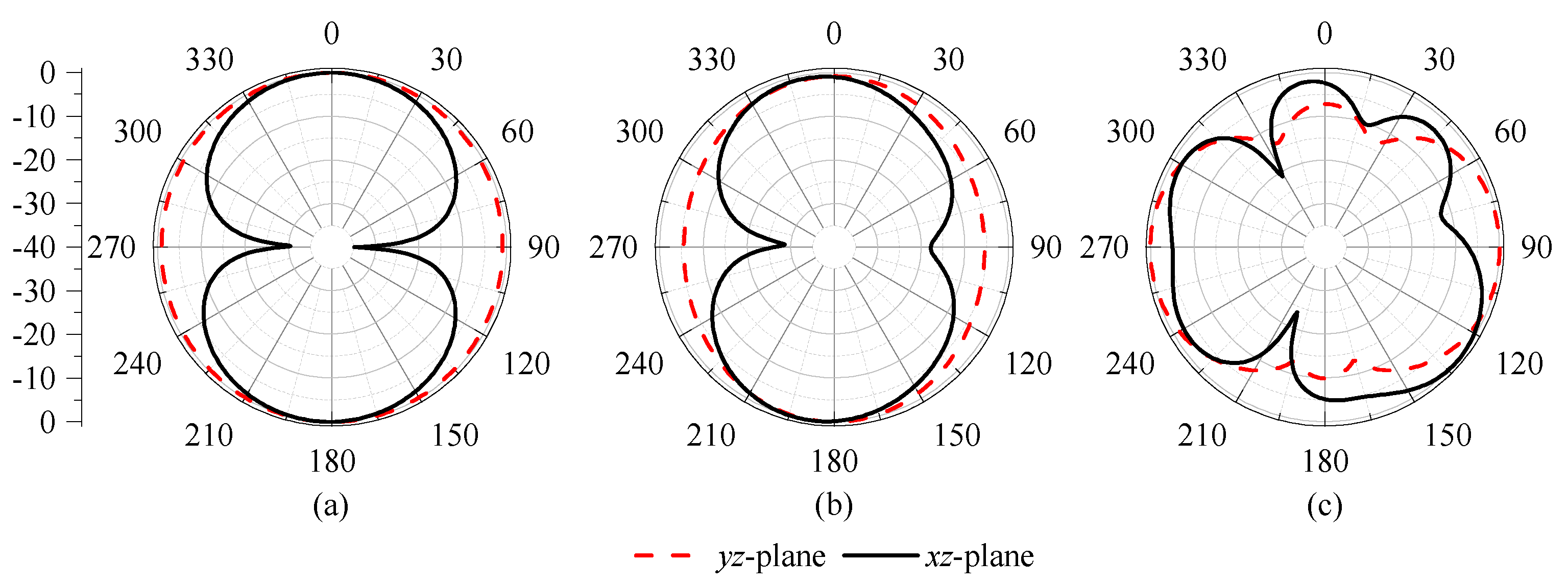
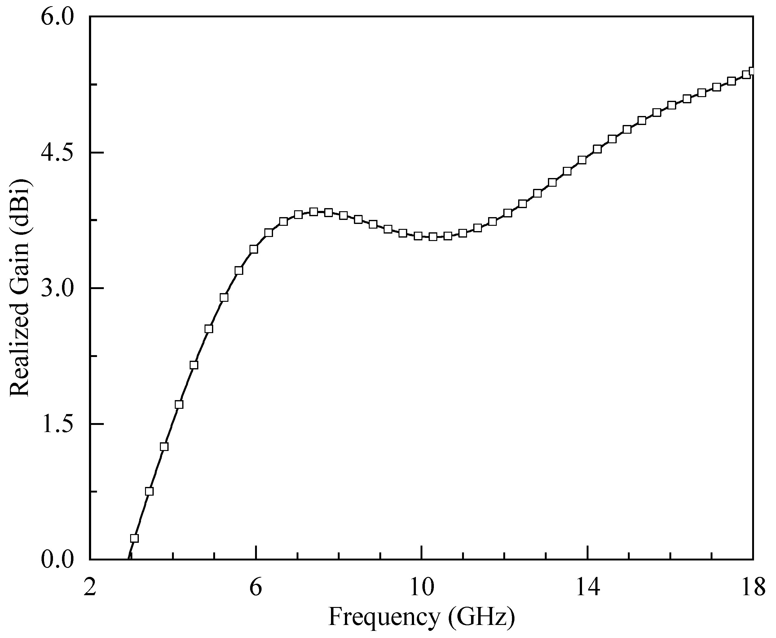
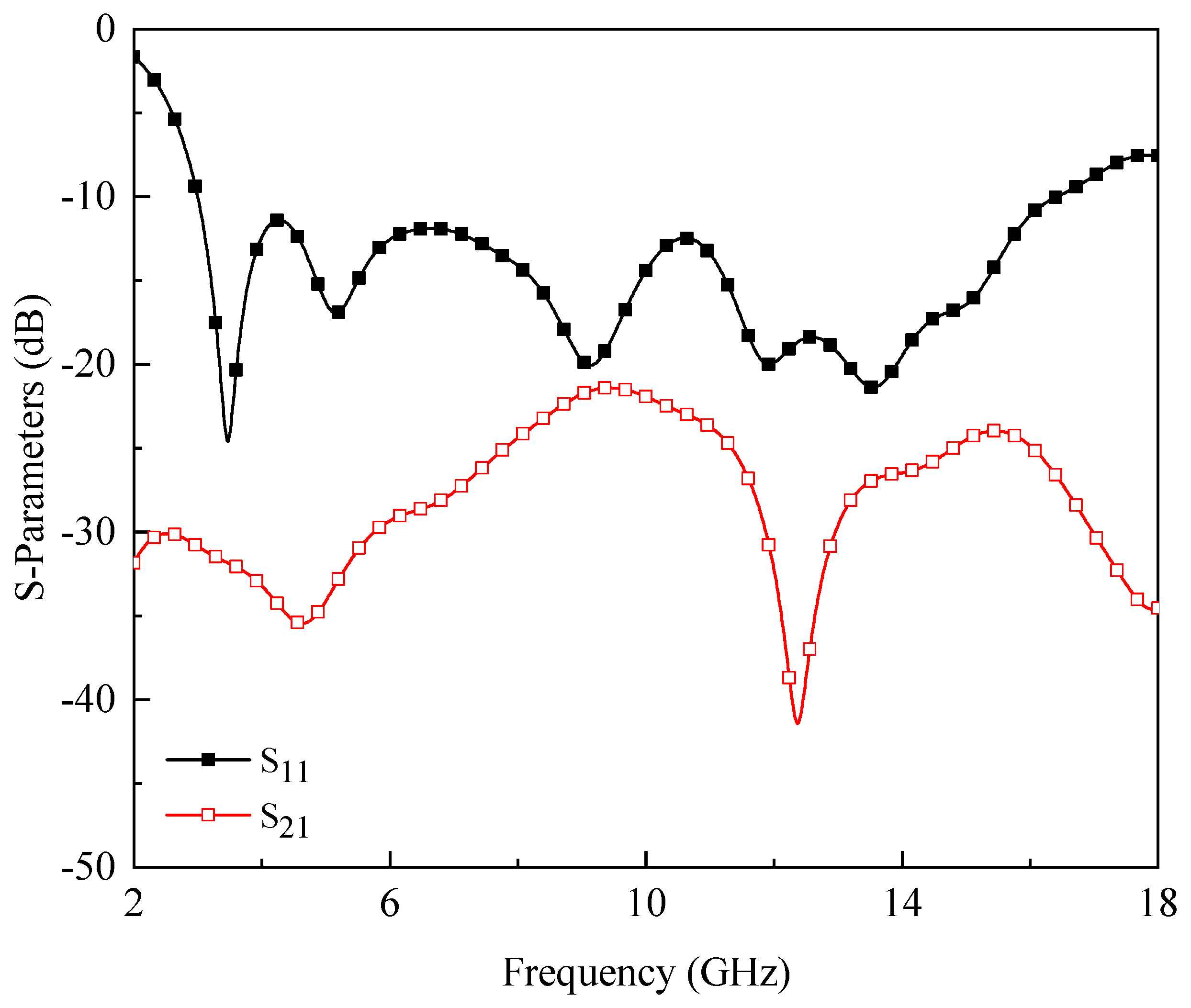
2.2. Simulation Results

The radiation characteristics for ϕ = 0 0 ( x z -plane) and ϕ = 90 0 ( y z -plane) of single antenna element are displayed in Figure 4. The radiation characteristics are computed at three different frequencies within the operating range, i.e., 4 GHz, 8 GHz, and 12 GHz. At lower frequencies, a dipole-like pattern is observed in x z -plane, while an omnidirectional pattern is noted in y z -plane as shown in Figure 4a,b. With increasing frequency, shown in Figure 4c, ripples are observed in the pattern for both planes. One potential reason for this could be the excitation of higher-order modes at higher frequencies [25].
Figure 5 shows the simulated gain response of the single antenna element. One can observe that the average gain value is ≈3.5 dBi within the operating range. Furthermore, the maximum gain is noted to be 5 dBi within the operating range.

3. Proposed MIMO Antenna

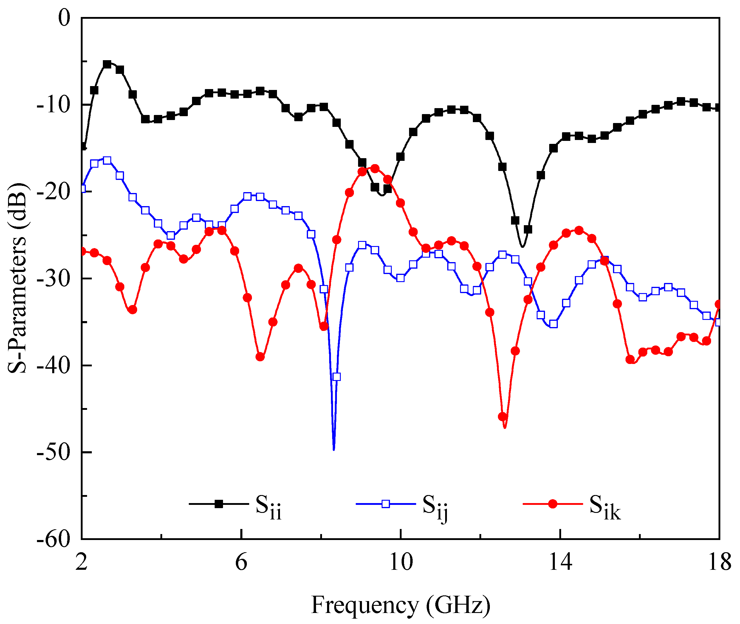
3.1. 2 × 2 MIMO Array

Before designing 4 × 4 MIMO array, a 2 × 2 MIMO antenna is designed by exploring polarization diversity technique as shown in Figure 6. All the design parameters of the array elements are identical to the single element design. The width of the array is increased to 55 mm denoted as W S 1 . A gap of about 9 mm (denoted as d 1 ) is introduced between the elements, which is less than λ /2 at the center frequency (10 GHz). Hence, the overall dimensions of 2 × 2 MIMO array are W S 1 × L S 1 = 55 × 26 mm2.
The simulated reflection and transmission coefficient results of the designed 2 × 2 MIMO array are shown in Figure 7. From the figure, one can observe that the simulated bandwidth for both antennas is noted to be 13.4 GHz (3–16.4 GHz). Furthermore, the isolation between the antenna elements is found to be >20 dB as illustrated in Figure 7.
The performance of the 2 × 2 MIMO array is also assessed by changing the distance between antenna elements and the results are shown in Figure 8a,b. For d 1 = 3 mm and 6 mm, a mismatch is observed in the impedance bandwidth from 3.84 GHz to 4.9 GHz as shown in Figure 8a. On the other hand, for these values, the isolation between the antenna elements is noted to be ≥18 dB and >20 dB, respectively, (see Figure 8b). For d 1 = 9 mm and 12 mm, the 2 × 2 MIMO array offers an impedance bandwidth of 13.4 GHz from 3 GHz to 16.4 GHz with isolation of >20 dB as shown in Figure 8a,b. Although d 1 = 12 mm offers improved isolation between antenna elements, it led to increased array size. Therefore, in this work, the value of d 1 is chosen to be 9 mm.

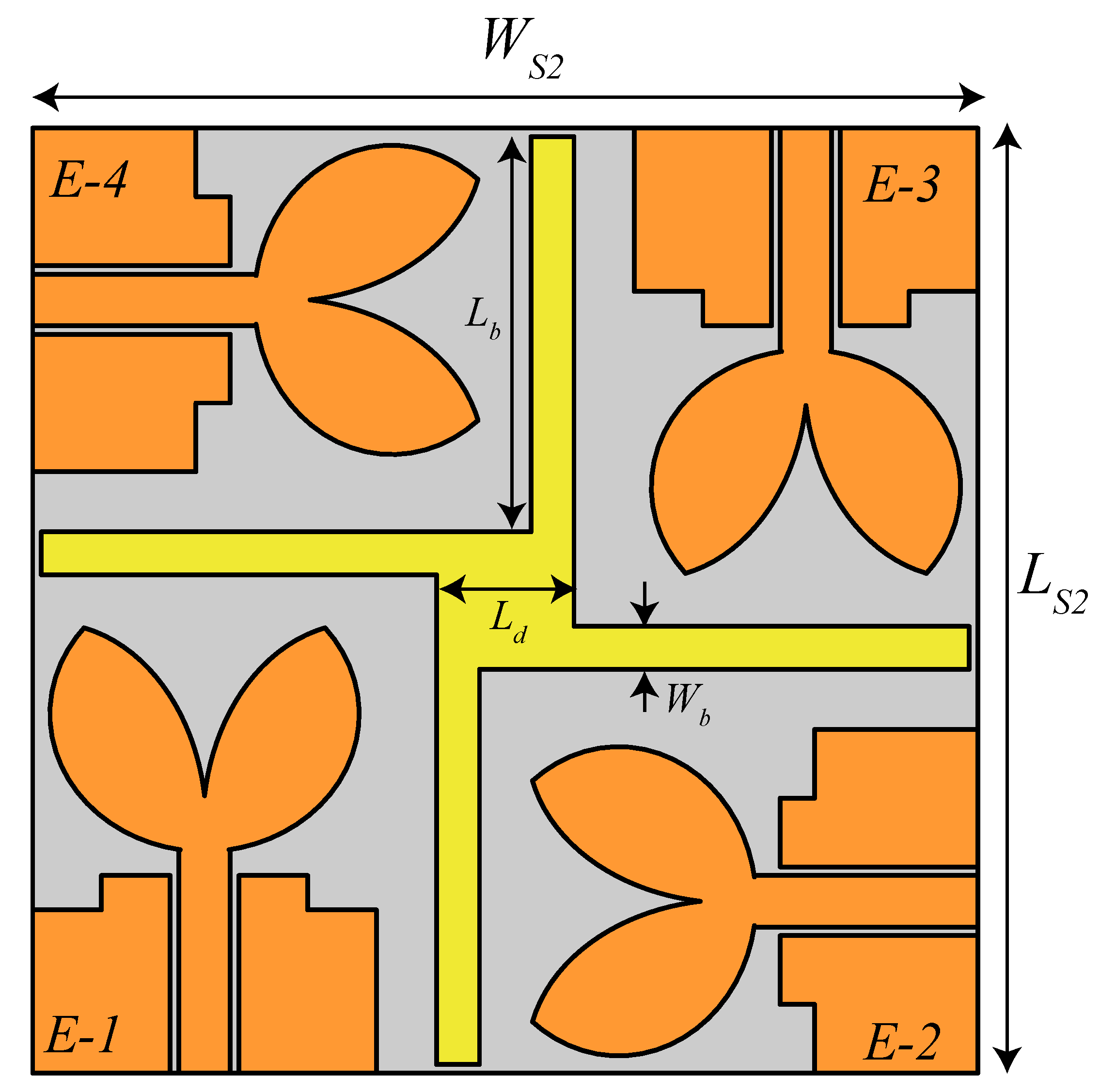
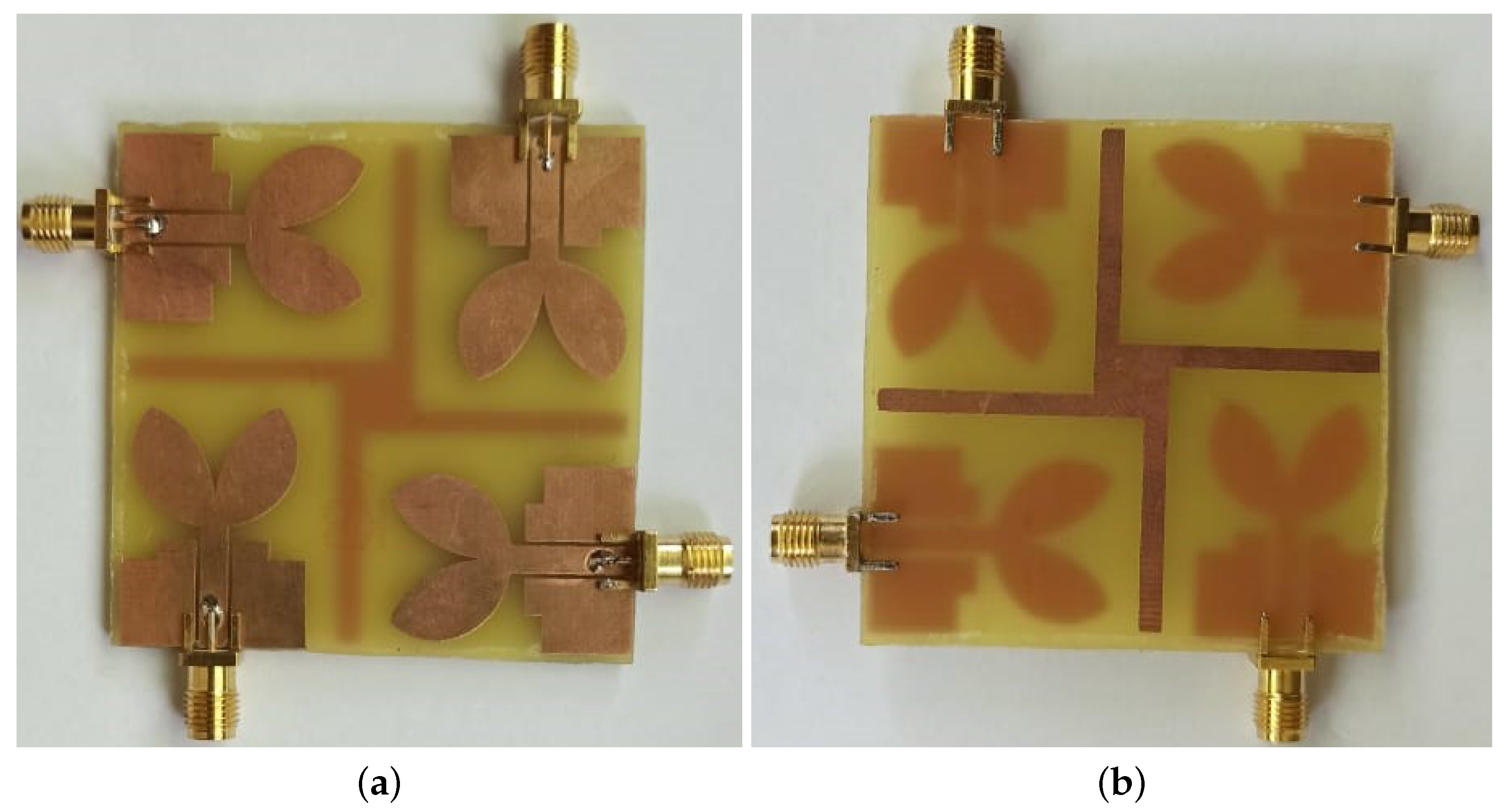
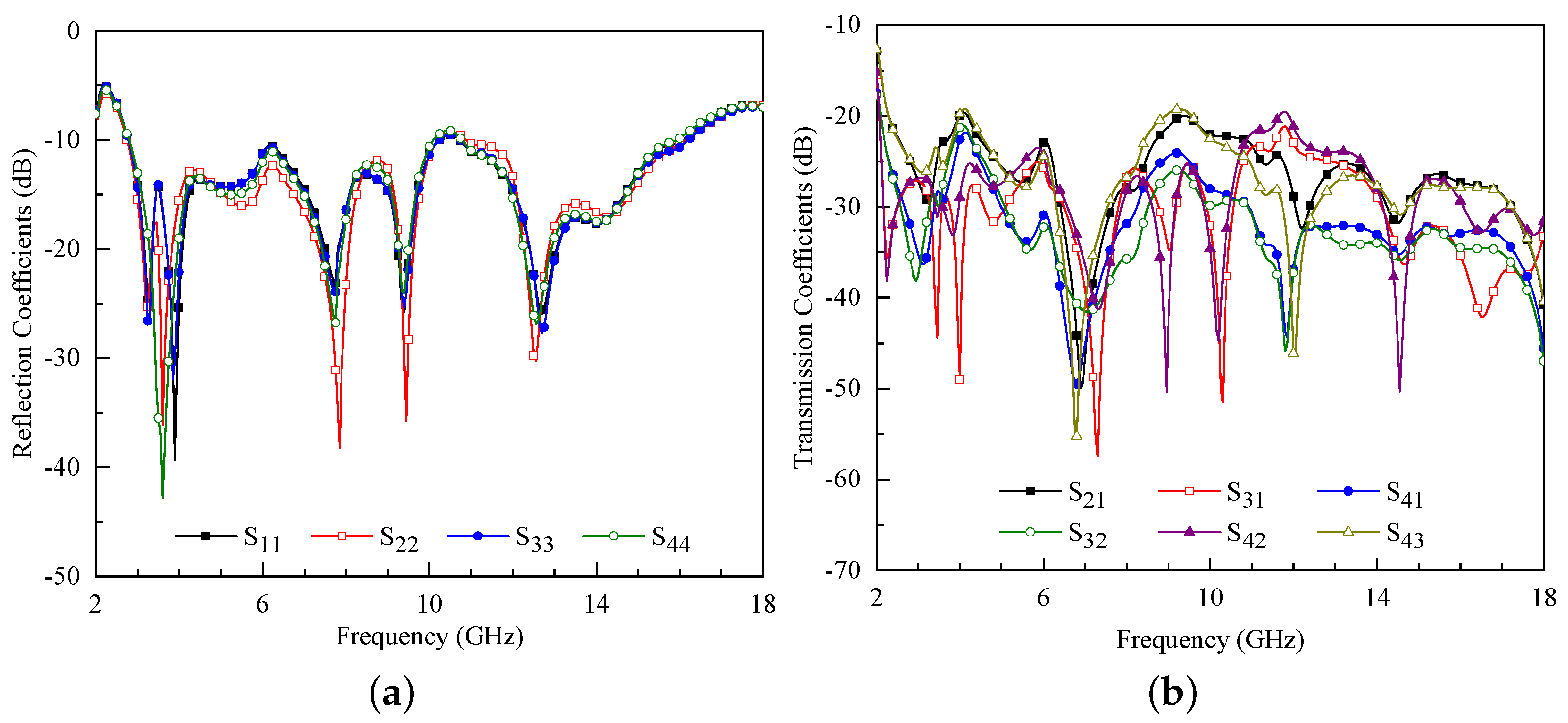
3.2. Proposed 4 × 4 MIMO Array

In this section, the design of the proposed 4 × 4 MIMO antenna is discussed. Each antenna element is arranged in the quadratic phase from the adjacent element, shown in Figure 9, which leads to a polarization diversity configuration. The parameters of each element are identical to the single element design, while the gap between them is increased to 9 mm. The optimized values of design parameters of 4 × 4 MIMO antenna are listed in Table 2. Furthermore, from Figure 9, one can observe that a fan-shaped decoupler is introduced at the bottom side of the substrate. The main purpose of the decoupler is to improve the isolation between the antenna elements. The dimensions of the decoupler are optimized during the simulation process to achieve the intended isolation performance (≥20 dB). The optimized values of the decoupler are also listed in Table 2.
For a better understanding of the decoupler’s necessity, a comparison of the isolation performance between the antenna elements with and without decoupler is presented in Figure 10. In the figure, S i j refers to the isolation between adjacent antenna elements and S i k represents the isolation between diagonal antenna elements. From the results, it can be concluded that the isolation between antenna elements improves when decoupler is introduced, shown in Figure 10, without affecting other parameters. Furthermore, this effect can also be verified from Figure 11 where the surface current distribution of 4 × 4 MIMO array is plotted without and with decoupler.
To understand the coupling behavior between antenna elements, only port-1 of the array is excited while the other ports are terminated with a matched load. The corresponding surface current results are shown in Figure 11. It can be observed from Figure 11a that without decoupler, the surface current generated by antenna 1 is influencing adjacent antenna elements, which corresponds to high mutual coupling. On the contrary, when the decoupler is inserted, shown in Figure 11b, this effect reduces and the isolation performance of the array improves. In addition, the utilization of a decoupler improves the radiation properties of the MIMO antenna. In Figure 12, three-dimensional (3D) radiation characteristics of the MIMO antenna are presented. From Figure 12a, one can observe that without a decoupler, the MIMO antenna exhibits a bi-directional radiation pattern but with high sidelobe levels (SLLs). On the other hand, when the decoupler is printed on the other side of the substrate, the pattern becomes more directional in both directions (0 and 180 ) as shown in Figure 12b.
Furthermore, the decoupler helps in stabilizing the gain of the proposed MIMO antenna compared to MIMO without decoupler. The gain performance of both configurations is shown in Figure 13. It is observed that without a decoupler, the average gain of the antenna is equal to 3.16 dBi, while in the presence of a decoupler, this value increased to 3.33 dBi. Therefore, it is worth mentioning that the decoupler has no effect on the radiation characteristics of the MIMO antenna.
The effect of the decoupler position on MIMO antenna performance is also studied and the corresponding results are shown in Figure 14. The performance is assessed by placing the decoupler on the top side and bottom side of the substrate. In the figure, the reflection coefficients are represented by S i i , (i∈ 1, 2, 3, 4), while the transmission coefficients for adjacent elements are denoted by S i j ( i , j ∈ 1, 2, 3, 4 and ij), and for diagonal elements, they are represented by S i k ( i , k ∈ 1, 2, 3, 4 and | i k | = 2). It is observed from Figure 14a that when a decoupler is designed on the top layer, a mismatch is observed in the band of interest ranging from 3.93 GHz to 4.95 GHz and from 5.76 GHz to 6.45 GHz. On the other hand, when the decoupler is placed on the bottom side of the substrate, an impedance bandwidth of 12.7 GHz is achieved starting from 2.9 GHz to 15.6 GHz as shown in Figure 14b. Furthermore, for both the configurations, no effect is observed on the isolation performance of the MIMO antenna.
From Figure 9, one can observe that the proposed MIMO antenna has four separate ground planes, which is not a practical approach. However, the separate ground planes help to reduce the ground current, and ultimately improve the isolation between the antenna elements [26]. Therefore, to assess the performance of the proposed MIMO antenna for practical applications, the proposed design is simulated with a common ground plane, and the results are shown in Figure 15. From the figure, it can be noted that the MIMO antenna with a common ground plane resonates from 3.39 GHz to 16.75 GHz. It is also observed from the figure that the common ground plane has a minor effect on the impedance matching in the frequency range of 4.78–7.04 GHz. In addition, the isolation between the adjacent antenna elements is noted to be >15 dB.

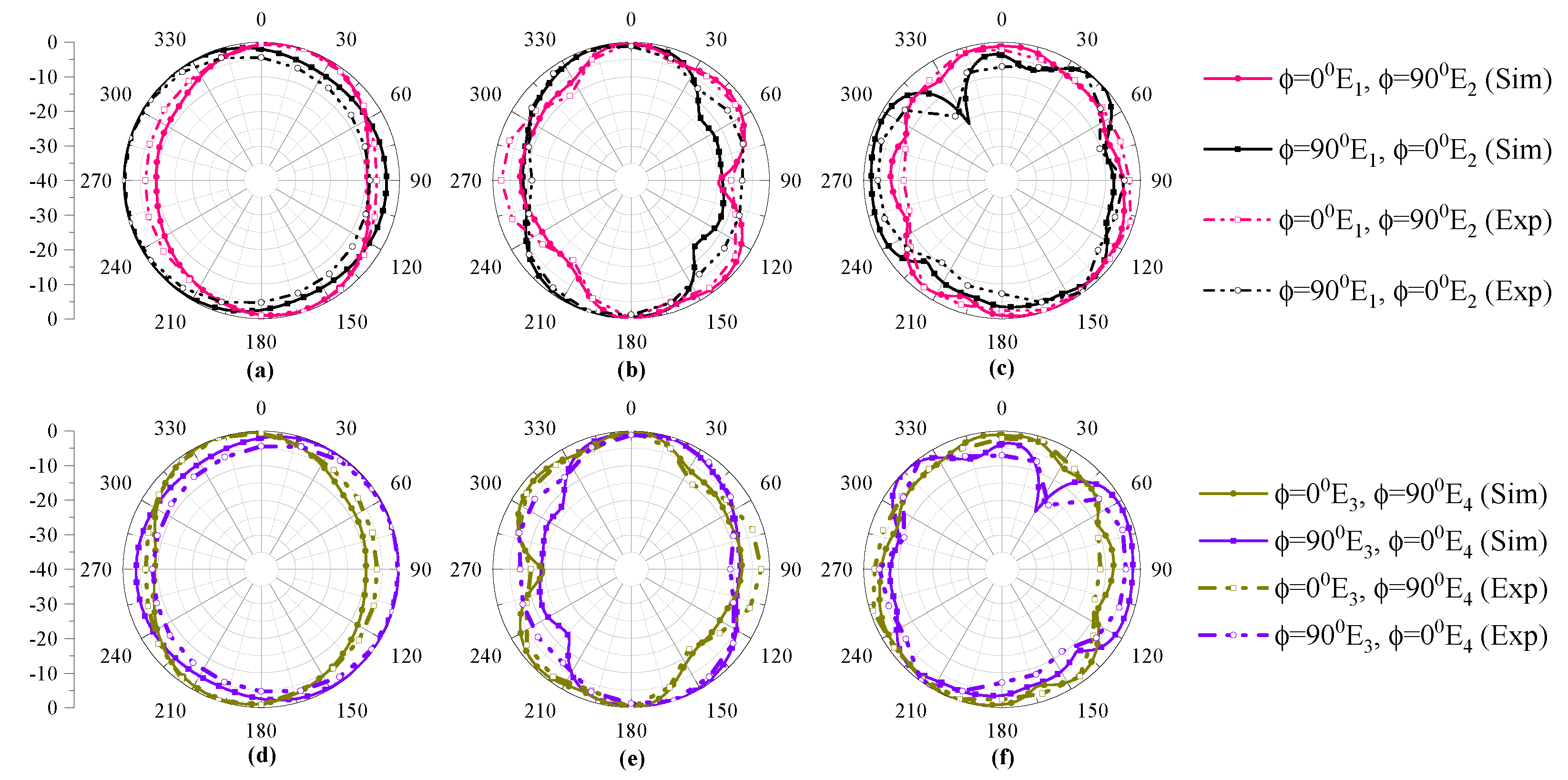
Fabrication and Measurements

A prototype of 4 × 4 MIMO array is fabricated, shown in Figure 16, and tested. A Precision Network Analyzer (PNA) E8363C by Agilent Technologies is utilized to calculate different reflection and transmission coefficients as shown in Figure 17a,b, respectively. It is evident from the figures that the measured responses of reflection and transmission coefficients are corroborating with the simulated data (Figure 14). The measured impedance bandwidth of the antenna elements is noted to be 13.3 GHz in the frequency range of 2.75–16.05 GHz, while the measured isolation between the antenna elements is ≥20 dB. The discrepancies observed between both results are due to fabrication intolerances.
For far-field measurements, the proposed MIMO antenna is tested in an anechoic chamber using a standard procedure. A horn antenna is used as a reference antenna, while the proposed MIMO antenna is placed on the other side.
The simulated and measured radiation characteristics of 4 × 4 MIMO array are shown in Figure 18. In the figure, the first row represents the radiation characteristics of antenna-1 and 2, while the second row shows the radiation characteristics of antenna-3 and 4. From the results, it is evident that the patterns are omnidirectional for both x z -plane ( ϕ = 0 ) and y z -plane ( ϕ = 90 ) within the operating region. The argument can be defended from the conventional theory of the antenna array design [27]. Furthermore, in polarization diversity configuration, the antenna elements are arranged in a quadratic orientation; hence, the radiation characteristics should also mimic the same behavior. It means that the x z -plane radiation pattern of antenna-1 should be equal to the y z -plane radiation pattern of antenna-2 and vice versa.

4. Assesment of MIMO Performance Parameters

Next, the performance parameters of MIMO are discussed in the following subsection. The performance is assessed in terms of ECC, DG, and mean effective gain (MEG).

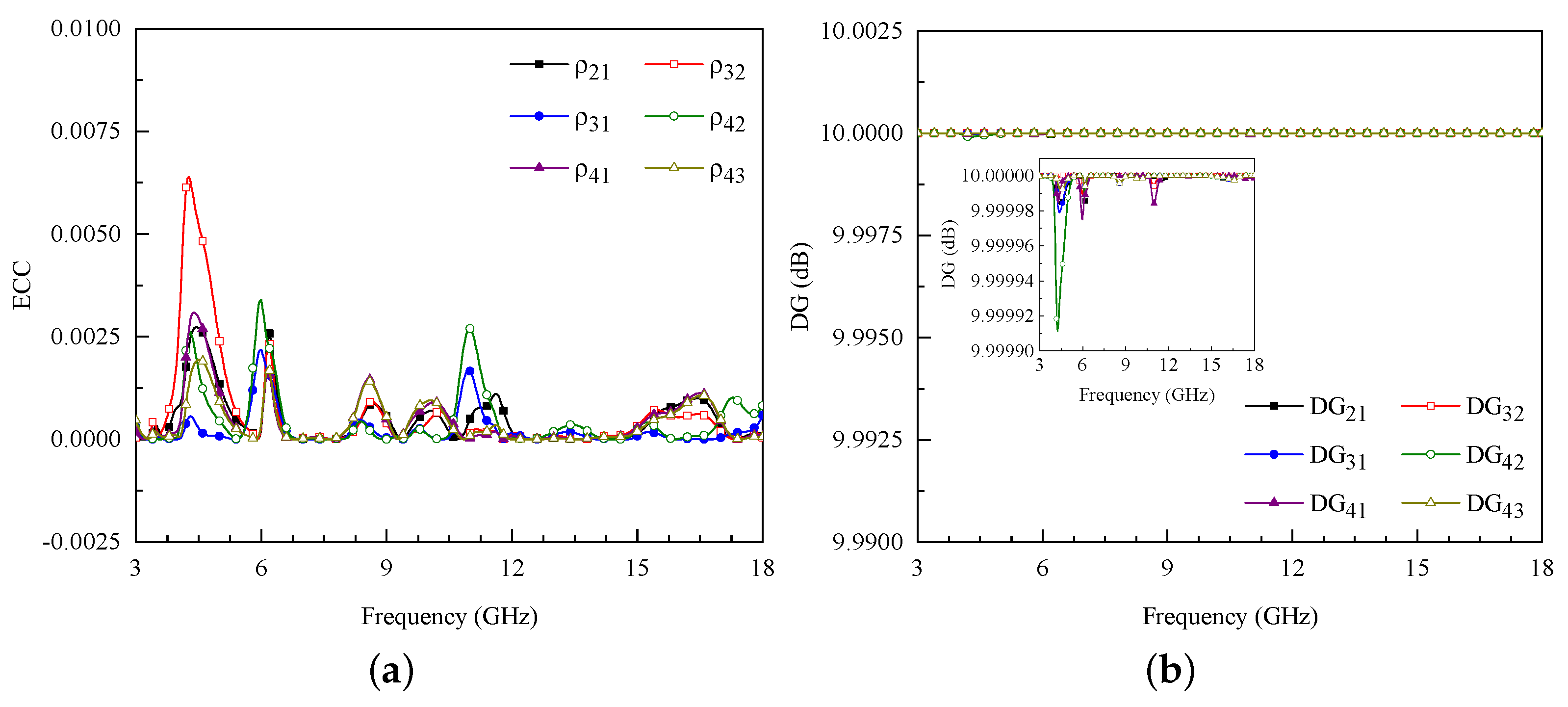
4.1. Envelope Correlation Coefficient

The envelope correlation coefficient (ECC) is considered to be an important factor to evaluate the MIMO system’s performance. It measures the degree of similarity among the received signals in a fading environment. Ideally, ECC should be zero; however, practically ECC should be ≤0.5 [28]. Mathematically, ECC can be calculated by using three-dimensional (3-D) far-field characteristics of the MIMO array as [29]:
ECC = 4 π E i ( θ , ϕ ) . E j * ( θ , ϕ ) d Ω 4 π E i ( θ , ϕ ) . E i * ( θ , ϕ ) d Ω 4 π E j ( θ , ϕ ) . E j * ( θ , ϕ ) d Ω
where E i and E j represents far-field radiation characteristics of port i and port j.
For the proposed array configuration, the value of ECC is <0.006 for the entire operating range as shown in Figure 19a. This result demonstrates good isolation between antenna elements, which is important for simultaneous operation.

4.2. Diversity Gain

Diversity gain (DG) is another important parameter to assess the performance of MIMO antennas. It can be calculated as [3]:
DG = 10 1 E C C 2
Figure 19b shows the DG of the proposed MIMO array. It can be concluded from the figure that the proposed MIMO array has DG ≈10 dB for the band of operation. A clear representation of DG in the operating bandwidth is shown in the inset of Figure 19b.

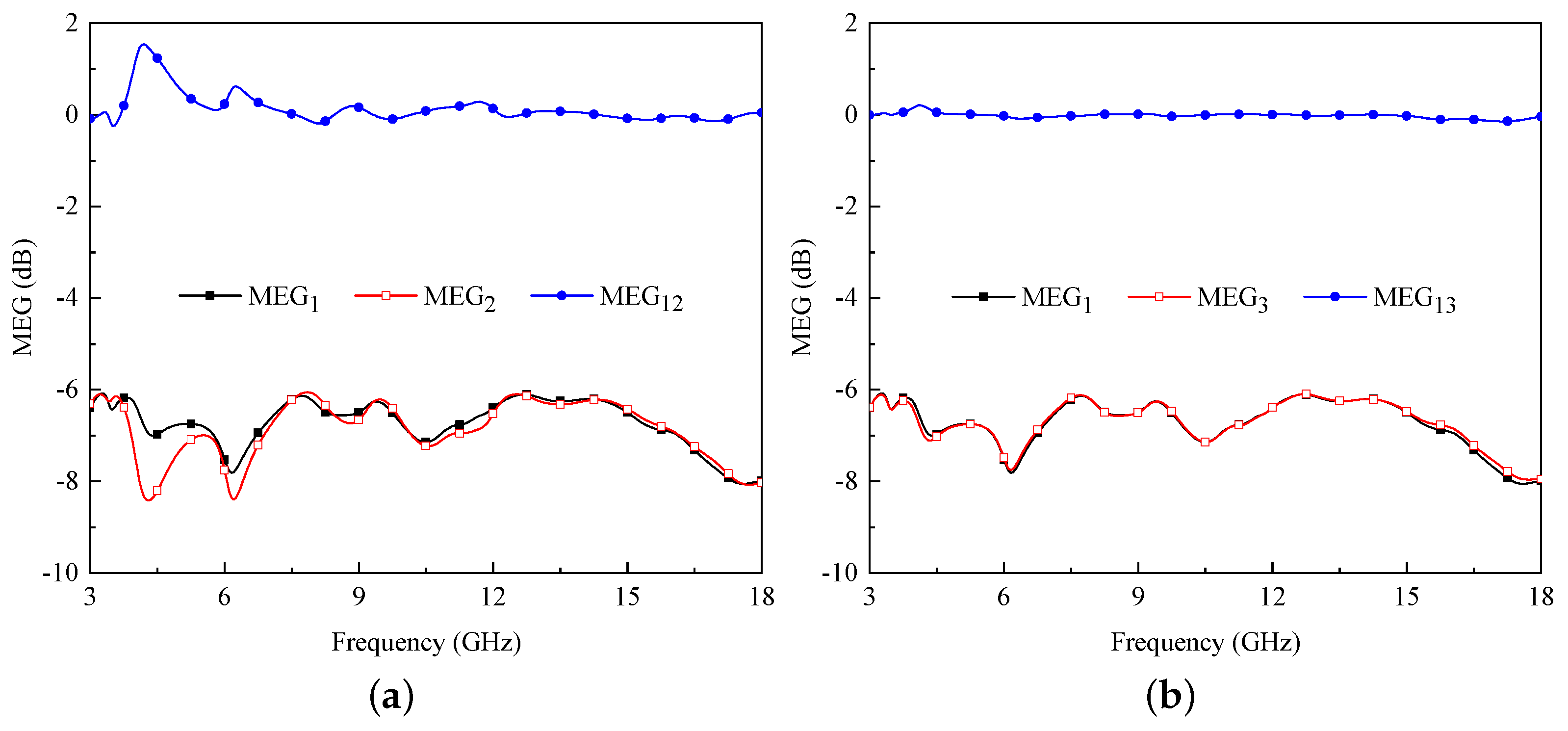
4.3. Mean Effective Gain

In a fading environment, mean effective gain (MEG) represents the measure of the amount of power received by the antenna elements compared to an isotropic antenna. One can compute MEG as [29]:
M E G i = 0.5 1 j = 1 N | S i j | 2 3 dB
and
M E G i M E G j 3 dB
The MEG 1 and MEG 2 can be written as [29]:
M E G 1 = 0.5 1 | S 11 | 2 | S 12 | 2 | S 13 | 2 | S 14 | 2
M E G 2 = 0.5 1 | S 21 | 2 | S 22 | 2 | S 23 | 2 | S 24 | 2
In a similar way, M E G 3 and M E G 4 can also be evaluated using Equation (3). For the proposed MIMO configuration, the value of M E G 1 , M E G 2 , and M E G 3 is less than −3 dB, which can be observed from Figure 20a,b.
It can also be noted from the figure that the difference MEG12 and MEG13 is less than 3 dB, shown in Figure 20a,b, respectively, within the entire operating range which satisfies the requirements of Equation (3).

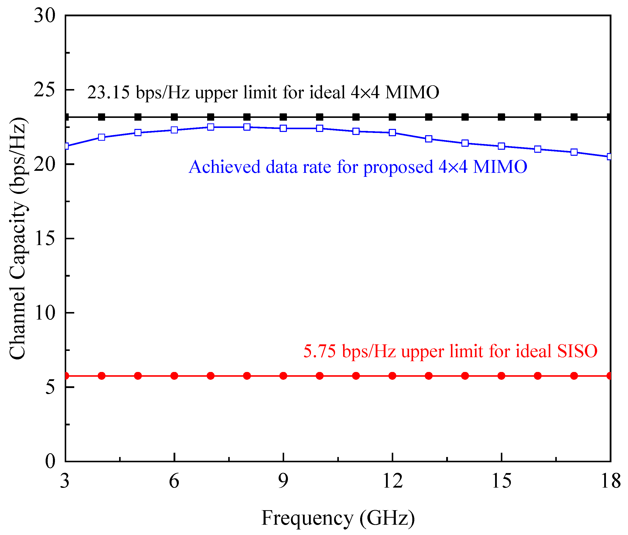
4.4. Channel Capacity

The ergodic channel capacity (CC) for the proposed MIMO antenna is calculated using the assumption used in [30], with the same amount of power provided to each transmit antenna and no prior knowledge of the channel state information (CSI) as calculated with the help of the following expression:
CC = E log 2 d e t I + S N R m t r H H T
where the channel matrix H can be computed as:
H = R T R G R R r e
The term E in Equation (7) denotes the expectation concerning channel realization, I represent the identity matrix, S N R means signal to noise ratio at the receiver end, m t r is the number of transmitting antennas, and ( . ) T represent the Hermitian transpose. Furthermore, it is assumed for this study that the transmitting antennas are uncorrelated with (ECC = 0) as represented by correlation matrix of R T r and receiver antenna correlation matrix given by R R r e . The randomness of the channel is represented by matrix G that contains complex Gaussian random numbers. Hence, the channel matrix contains entries with dimensions of 4 × 4 matrix for 4-elements. The ergodic CC is obtained by averaging over 10,000 independent and identical Rayleigh fading realizations with reference S N R of 20 dB [31]. The CC of the proposed MIMO antenna system is illustrated in Figure 21. As can be observed from the figure that the calculated CC of the proposed design for 4 × 4 MIMO within the desired frequency range is better than 20 bps/Hz whereas, for the ideal scenario, this value is equal to 23.15 bps/Hz [32].
A comparative study between the proposed and previously reported 4 × 4 MIMO arrays is provided in Table 3. From the data, one can observe that the proposed MIMO array performs better and 10–52.73% physically compact compared to the designs of [9,14,16,19,24] and electrically small compared to the designs reported in [9,16,19,24]. On the other hand, the designs reported in [1,6,18] are compact than the proposed design; however, their performance lacks either in terms of bandwidth or isolation. In addition, the diversity performance of the proposed MIMO antenna is much better compared to the designs of [1,6,9,14,16,18].

5. Conclusion

A design of 4 × 4 MIMO antenna array is presented for UWB applications. The single element of the MIMO array is comprised of a modified CPW-fed double overt-leaf-shaped radiating patch. The results demonstrate that the antenna operates in the frequency range of 3.3–16.5 GHz. It is also shown that the proposed antenna offers an average gain of 3.5 dBi for the entire operating range. Furthermore, a 4 × 4 MIMO array is designed to demonstrate the performance of the proposed antenna for UWB MIMO applications. The results of the MIMO configuration demonstrate an impedance bandwidth starting from 2.75 to 16.05 GHz and also offer effective isolation (≥20 dB) between antenna elements.

Author Contributions

Conceptualization, S.A.; methodology, S.A. and U.R.; software, S.A. and U.R.; validation, U.R.; formal analysis, U.R.; investigation, U.R.; resources, R.U., S.U., S.K. and M.D.; writing—original draft preparation, S.A.; writing—review and editing, U.R. and M.D.; visualization, S.A.; supervision, U.R.; project administration, R.U. and S.U. All authors have read and agreed to the published version of the manuscript.

Funding

This work has been funded by King Saud University, Riyadh, Saudi Arabia through Researchers Supporting Project number (RSP-2021/58).

Institutional Review Board Statement

Not applicable.

Informed Consent Statement

Not applicable.

Data Availability Statement

No new data were created or analyzed in this study.

Acknowledgments

The authors sincerely appreciate funding from Researchers Supporting Project number (RSP-2021/58), King Saud University, Riyadh, Saudi Arabia.

Conflicts of Interest

The authors declare no conflict of interest.

References

  1. Tripathi, S.; Mohan, A.; Yadav, S. A compact Koch fractal UWB MIMO antenna with WLAN band-rejection. IEEE Antennas Wirel. Propag. Lett. 2015, 14, 1565–1568. [Google Scholar] [CrossRef]
  2. Khan, M.S.; Capobianco, A.D.; Asif, S.M.; Anagnostou, D.E.; Shubair, R.M.; Braaten, B.D. A compact CSRR-enabled UWB diversity antenna. IEEE Antennas Wirel. Propag. Lett. 2016, 16, 808–812. [Google Scholar] [CrossRef]
  3. Iqbal, A.; Saraereh, O.A.; Ahmad, A.W.; Bashir, S. Mutual coupling reduction using F-shaped stubs in UWB-MIMO antenna. IEEE Access 2017, 6, 2755–2759. [Google Scholar] [CrossRef]
  4. Chandel, R.; Gautam, A.K.; Rambabu, K. Design and packaging of an eye-shaped multiple-input–multiple-output antenna with high isolation for wireless UWB applications. IEEE Trans. Components Packag. Manuf. Technol. 2018, 8, 635–642. [Google Scholar] [CrossRef]
  5. Chandel, R.; Gautam, A.K.; Rambabu, K. Tapered fed compact UWB MIMO-diversity antenna with dual band-notched characteristics. IEEE Trans. Antennas Propag. 2018, 66, 1677–1684. [Google Scholar] [CrossRef]
  6. Tang, Z.; Wu, X.; Zhan, J.; Hu, S.; Xi, Z.; Liu, Y. Compact UWB-MIMO antenna with high isolation and triple band-notched characteristics. IEEE Access 2019, 7, 19856–19865. [Google Scholar] [CrossRef]
  7. Dey, A.B.; Pattanayak, S.S.; Mitra, D.; Arif, W. Investigation and design of enhanced decoupled UWB MIMO antenna for wearable applications. Microw. Opt. Technol. Lett. 2020, 63, 845–861. [Google Scholar] [CrossRef]
  8. Bahmanzadeh, F.; Mohajeri, F. Simulation and fabrication of a high-isolation very compact MIMO antenna for ultra-wide band applications with dual band-notched characteristics. AEU-Int. J. Electron. Commun. 2021, 128, 153505. [Google Scholar] [CrossRef]
  9. Wu, W.; Yuan, B.; Wu, A. A quad-element UWB-MIMO antenna with band-notch and reduced mutual coupling based on EBG structures. Int. J. Antennas Propag. 2018, 2018, 8490740. [Google Scholar] [CrossRef] [Green Version]
  10. Naidu, P.R.T.; Saha, C.; Krishna, K.V.; Shaik, L.A.; Siddiqui, J.Y.; Antar, Y. Compact multiple EBG cells loaded UWB-narrowband antenna pair with high isolation for cognitive radio (CR) based MIMO applications. AEU-Int. J. Electron. Commun. 2020, 127, 153420. [Google Scholar] [CrossRef]
  11. Kumar, N.; Kiran, K.U. Meander-line electromagnetic bandgap structure for UWB MIMO antenna mutual coupling reduction in E-plane. AEU-Int. J. Electron. Commun. 2020, 127, 153423. [Google Scholar] [CrossRef]
  12. Modak, S.; Khan, T. A slotted UWB-MIMO antenna with quadruple band-notch characteristics using mushroom EBG structure. AEU-Int. J. Electron. Commun. 2021, 134, 153673. [Google Scholar] [CrossRef]
  13. Bilal, M.; Saleem, R.; Abbasi, H.H.; Shafique, M.F.; Brown, A.K. An FSS-based nonplanar quad-element UWB-MIMO antenna system. IEEE Antennas Wirel. Propag. Lett. 2016, 16, 987–990. [Google Scholar] [CrossRef]
  14. Rekha, V.S.D.; Pardhasaradhi, P.; Madhav, B.T.P.; Devi, Y.U. Dual Band Notched Orthogonal 4-Element MIMO Antenna with Isolation for UWB Applications. IEEE Access 2020, 8, 145871–145880. [Google Scholar] [CrossRef]
  15. Tiwari, R.N.; Singh, P.; Kanaujia, B.K. A compact UWB MIMO antenna with neutralization line for WLAN/ISM/mobile applications. Int. J. RF Microw. Comput.-Aided Eng. 2019, 29, e21907. [Google Scholar] [CrossRef]
  16. Kumar, S.; Lee, G.H.; Kim, D.H.; Mohyuddin, W.; Choi, H.C.; Kim, K.W. Multiple-input-multiple-output/diversity antenna with dual band-notched characteristics for ultra-wideband applications. Microw. Opt. Technol. Lett. 2020, 62, 336–345. [Google Scholar] [CrossRef]
  17. Ramanujam, P.; Venkatesan, P.R.; Arumugam, C.; Ponnusamy, M. Design of miniaturized super wideband printed monopole antenna operating from 0.7 to 18.5 GHz. AEU-Int. J. Electron. Commun. 2020, 123, 153273. [Google Scholar] [CrossRef]
  18. Khan, A.A.; Naqvi, S.A.; Khan, M.S.; Ijaz, B. Quad port miniaturized MIMO antenna for UWB 11 GHz and 13 GHz frequency bands. AEU-Int. J. Electron. Commun. 2021, 131, 153618. [Google Scholar] [CrossRef]
  19. Hasan, M.N.; Chu, S.; Bashir, S. A DGS monopole antenna loaded with U-shape stub for UWB MIMO applications. Microw. Opt. Technol. Lett. 2019, 61, 2141–2149. [Google Scholar] [CrossRef]
  20. Sohi, A.K.; Kaur, A. A complementary Sierpinski gasket fractal antenna array integrated with a complementary Archimedean defected ground structure for portable 4G/5G UWB MIMO communication devices. Microw. Opt. Technol. Lett. 2020, 62, 2595–2605. [Google Scholar] [CrossRef]
  21. Wang, E.; Wang, W.; Tan, X.; Wu, Y.; Gao, J.; Liu, Y. A UWB MIMO slot antenna using defected ground structures for high isolation. Int. J. RF Microw. Comput.-Aided Eng. 2020, 30, e22155. [Google Scholar] [CrossRef]
  22. Kumar, A.; Ansari, A.Q.; Kanaujia, B.K.; Kishor, J. A novel ITI-shaped isolation structure placed between two-port CPW-fed dual-band MIMO antenna for high isolation. AEU-Int. J. Electron. Commun. 2019, 104, 35–43. [Google Scholar] [CrossRef]
  23. Wang, L.; Du, Z.; Yang, H.; Ma, R.; Zhao, Y.; Cui, X.; Xi, X. Compact UWB MIMO antenna with high isolation using fence-type decoupling structure. IEEE Antennas Wirel. Propag. Lett. 2019, 18, 1641–1645. [Google Scholar] [CrossRef]
  24. Raheja, D.K.; Kanaujia, B.K.; Kumar, S. Compact four-port MIMO antenna on slotted-edge substrate with dual-band rejection characteristics. Int. J. RF Microw. Comput.-Aided Eng. 2019, 29, e21756. [Google Scholar] [CrossRef]
  25. Rafique, U.; Din, S.U.; Khalil, H. Compact CPW-fed Super Wideband Planar Elliptical Antenna. Int. J. Microw. Wirel. Technol. 2021, 13, 407–414. [Google Scholar] [CrossRef]
  26. Sharawi, M.S. Printed multi-band MIMO antenna systems and their performance metrics [wireless corner]. IEEE Antennas Propag. Mag. 2013, 55, 218–232. [Google Scholar] [CrossRef]
  27. Balanis, C.A. Antenna Theory: Analysis and Design; John Wiley & Sons: Hoboken, NJ, USA, 2015. [Google Scholar]
  28. Koohestani, M.; Moreira, A.A.; Skrivervik, A.K. A novel compact CPW-fed polarization diversity ultrawideband antenna. IEEE Antennas Wirel. Propag. Lett. 2014, 13, 563–566. [Google Scholar] [CrossRef]
  29. Rafique, U.; Agarwal, S.; Nauman, N.; Khalil, H.; Ullah, K. Inset-fed Planar Antenna Array for Dual-band 5G MIMO Applications. Prog. Electromagn. Res. C 2021, 112, 83–98. [Google Scholar] [CrossRef]
  30. Ullah, R.; Ullah, S.; Faisal, F.; Ullah, R.; Mabrouk, I.B.; Al Hasan, M.J.; Kamal, B. A novel multi-band and multi-generation (2G, 3G, 4G, and 5G) 9-elements MIMO antenna system for 5G smartphone applications. Wirel. Netw. 2021, 27, 4825–4837. [Google Scholar] [CrossRef]
  31. Abdullah, M.; Kiani, S.H.; Abdulrazak, L.F.; Iqbal, A.; Bashir, M.; Khan, S.; Kim, S. High-performance multiple-input multiple-output antenna system for 5G mobile terminals. Electronics 2019, 8, 1090. [Google Scholar] [CrossRef] [Green Version]
  32. Li, Y.; Zou, H.; Wang, M.; Peng, M.; Yang, G. Eight-element MIMO antenna array for 5G/Sub-6GHz indoor micro wireless access points. In Proceedings of the 2018 International Workshop on Antenna Technology (iWAT), Nanjing, China, 5–7 March 2018; pp. 1–4. [Google Scholar]
Figure 1. Design of the double overt-leaf shaped UWB antenna.
Electronics 10 03140 g001
Figure 2. Simulated S 11 of different antenna designs along with their schematics.
Electronics 10 03140 g002
Figure 3. S 11 characteristics of single antenna element for varying (a) W g h , (b) L g h , and (c) t.
Electronics 10 03140 g003
Figure 4. Simulated radiation characteristics of single antenna element at (a) 4 GHz, (b) 8 GHz, and (c) 12 GHz.
Electronics 10 03140 g004
Figure 5. Simulated realized gain of single antenna element.
Electronics 10 03140 g005
Figure 6. Schematic representation of 2 × 2 MIMO array.
Electronics 10 03140 g006
Figure 7. Simulated reflection and transmission coefficient results of 2 × 2 MIMO array.
Electronics 10 03140 g007
Figure 8. (a) Reflection and (b) transmission coefficient of the 2 × 2 MIMO array for varying d 1 .
Electronics 10 03140 g008
Figure 9. Schematic of the proposed 4 × 4 MIMO array.
Electronics 10 03140 g009
Figure 10. Isolation performance of 4 × 4 MIMO array without and with decoupler.
Electronics 10 03140 g010
Figure 11. Surface current distribution of 4 × 4 MIMO array (a) without and (b) with decoupler.
Electronics 10 03140 g011
Figure 12. 3D radiation characteristics of 4 × 4 MIMO array (a) without and (b) with decoupler.
Electronics 10 03140 g012
Figure 13. Realized gain result of 4 × 4 MIMO array without and with decoupler.
Electronics 10 03140 g013
Figure 14. Simulated reflection and transmission coefficients of 4 × 4 MIMO array when decoupler is placed on (a) top and (b) bottom side of the substrate.
Electronics 10 03140 g014
Figure 15. Simulated reflection and transmission coefficients of 4 × 4 MIMO array with common ground plane.
Electronics 10 03140 g015
Figure 16. Fabricated prototype of the proposed 4 × 4 MIMO array (a) front view and (b) back view.
Electronics 10 03140 g016
Figure 17. Measured (a) reflection and (b) transmission coefficients of the proposed 4 × 4 MIMO array.
Electronics 10 03140 g017
Figure 18. Simulated and measured radiation patterns of the proposed 4 × 4 MIMO array at (a,d) 4 GHz, (b,e) 8 GHz and (c,f) 12 GHz.
Electronics 10 03140 g018
Figure 19. (a) Envelope correlation coefficient and (b) diversity gain of the proposed 4 × 4 MIMO array (inset of (b) shows zoomed view of diversity gain).
Electronics 10 03140 g019
Figure 20. Mean effective gain of 4 × 4 MIMO array between (a) port 1 and 2, and (b) port 1 and 3.
Electronics 10 03140 g020
Figure 21. Ergodic channel capacity of the proposed 4 × 4 MIMO antenna.
Electronics 10 03140 g021
Table 1. Optimized values of single element design (all values are in mm).
ParameterValueParameterValueParameterValue
W S 20 L S 26 W f 3
W g 8 L g 11.5g0.5
W g h 4 L g h 2t1.5
Table 2. Optimized design parameters of the proposed 4 × 4 MIMO array (all values are in mm).
ParameterValueParameterValueParameterValue
L S 2 55 W S 2 55 W b 2.5
L b 23 L d 8
Table 3. Comparison among proposed and previously presented 4 × 4 MIMO arrays.
Ref.MIMO SizeSubstrateBandwidth
(GHz)
Isolation
(dB)
ECCDG
(dB)
% Size Reduction
(mm2)(λ2)
[1]45 × 450.3 × 0.3FR-4 ( ϵ r  = 4.4)2–10.6≥17<0.01
[6]39 × 390.3 × 0.3FR-4 ( ϵ r  = 4.4)2.3–13.75≥20<0.02>9.5
[9]60 × 600.6 × 0.6FR-4 ( ϵ r  = 4.4)3–16.2≥17.5<0.115.97
[14]80 × 800.43 × 0.43FR-4 ( ϵ r  = 4.4)2.1–20≥25<0.0252.73
[16]72 × 720.673 × 0.673FR-4 ( ϵ r  = 4.4)2.8–10.6≥18<0.0641.65
[18]40 × 400.4 × 0.4TMM-4 ( ϵ r  = 4.4)3–10.6≥15<0.4>9.95
[19]80 × 800.849 × 0.849Taconic RF30 ( ϵ r  = 3)3.18–11.5≥1552.73
[24]58 × 580.58 × 0.58FR-4 ( ϵ r  = 4.4)3–13.5≥23<0.0089.9810
This Work55 × 550.505 × 0.505FR-4 ( ϵ r  = 4.4)2.75–16.05≥20<0.006∼10
Publisher’s Note: MDPI stays neutral with regard to jurisdictional claims in published maps and institutional affiliations.

