
An Eight Element Dual Band Antenna for Future 5G Smartphones

 , , ,
, , ,  , and
, and
Abstract
:1. Introduction
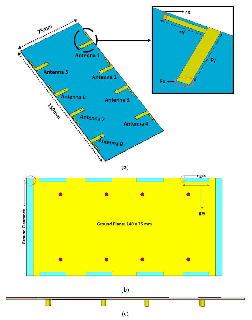
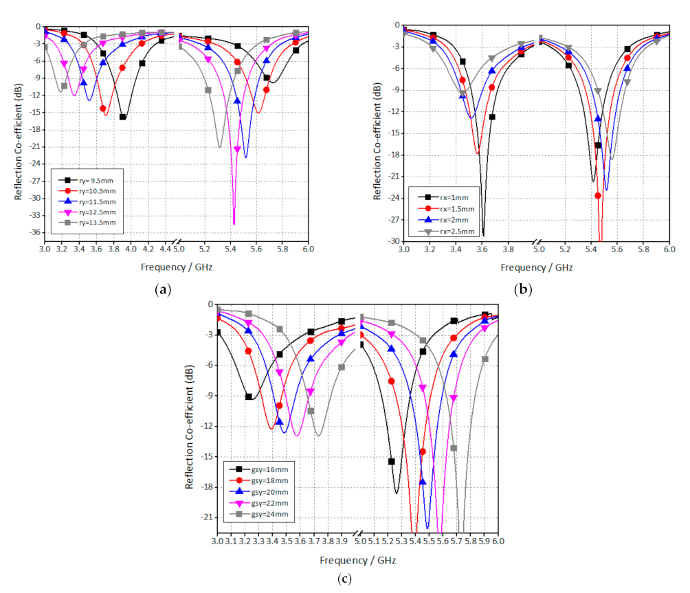
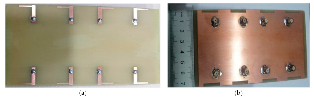
2. Antenna Design
3. Results and Discussions
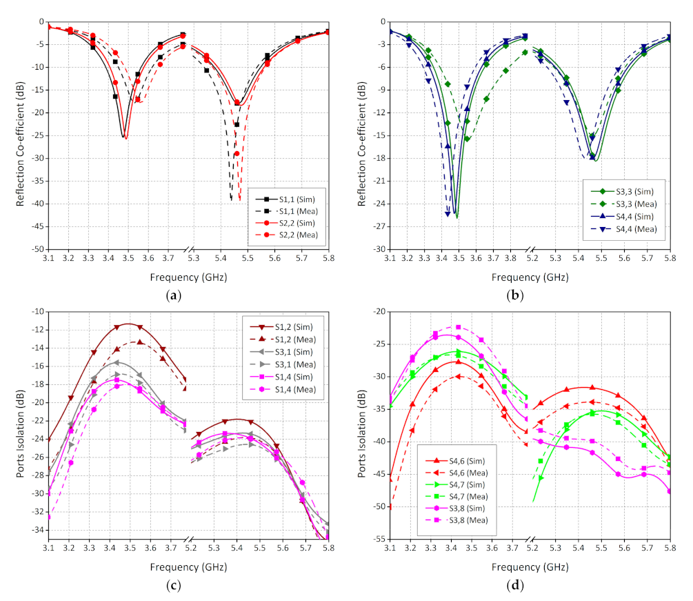
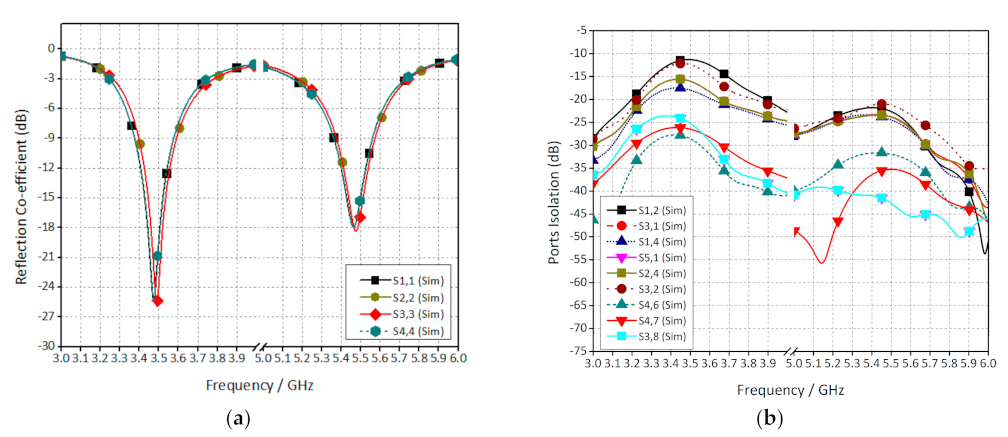
3.1. S-Parameters
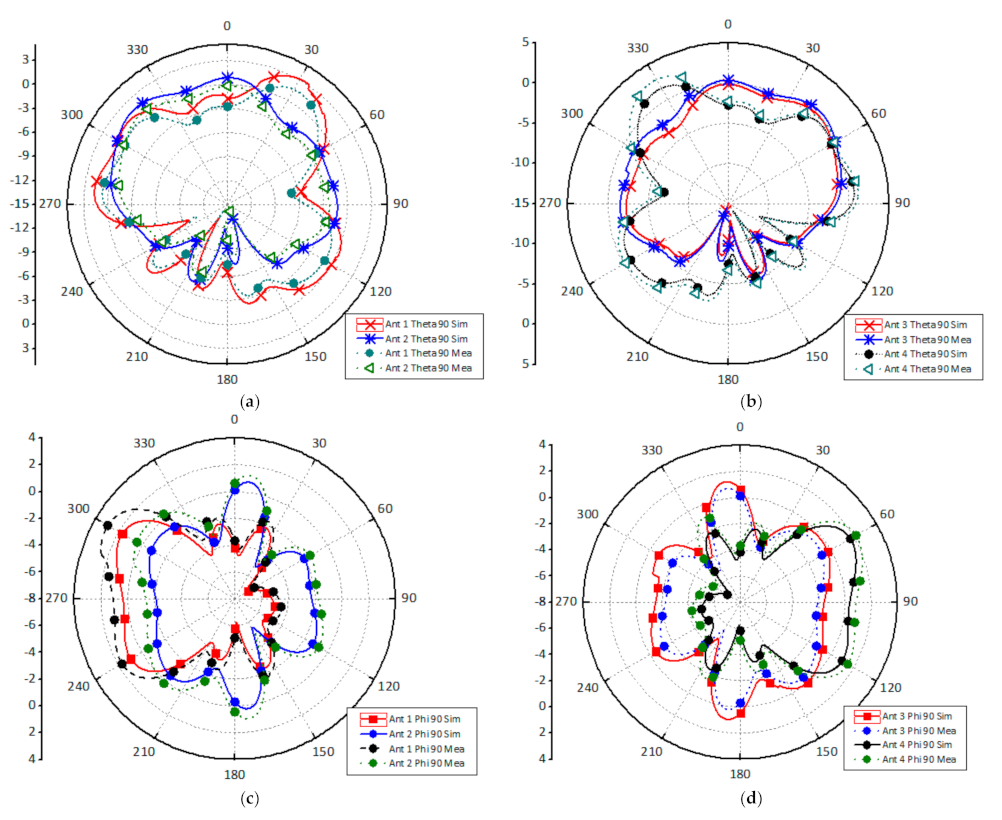
3.2. Radiation Patterns
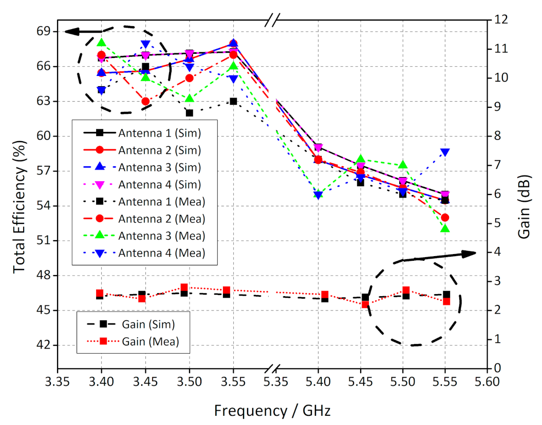
3.3. Performance Parameters
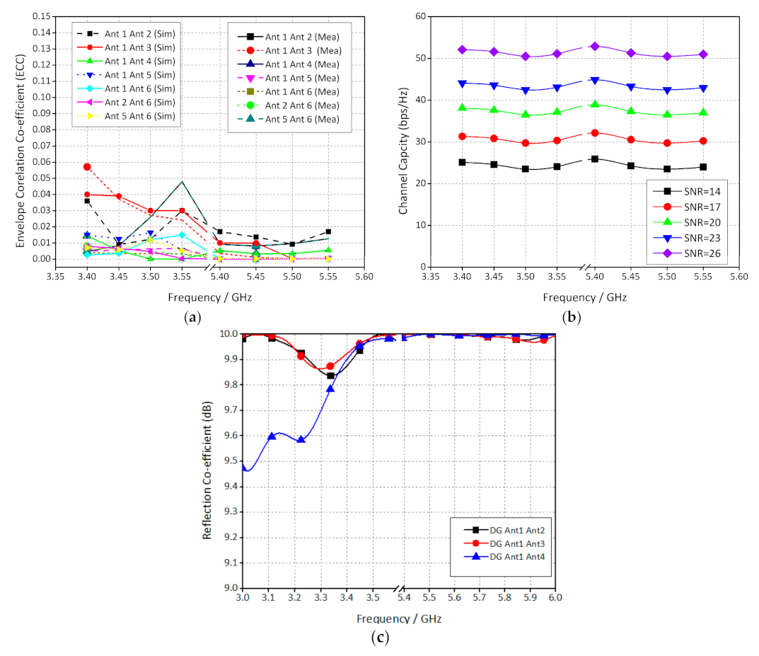
3.4. MIMO Performance Parameters
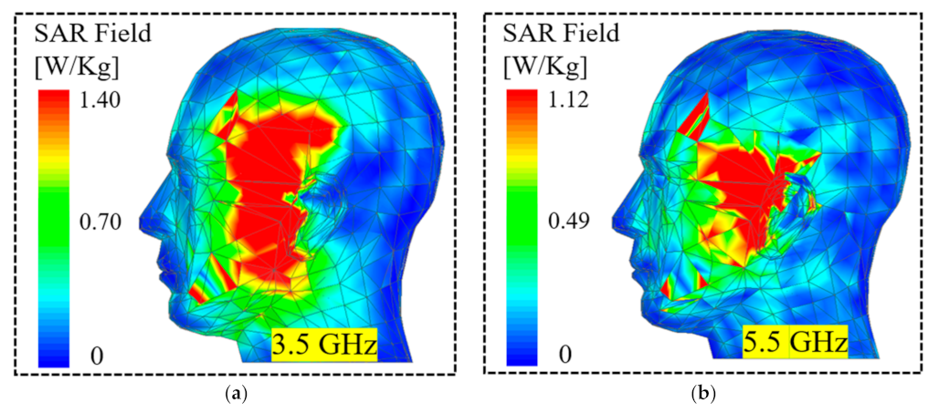
3.5. SAR Analysis
4. Conclusions
Author Contributions
Funding
Data Availability Statement
Conflicts of Interest
References
- Anitha, R.; Vinesh, P.V.; Prakash, K.C.; Mohanan, P.; Vasudevan, K. A Compact Quad Element Slotted Ground Wideband Antenna for MIMO Applications. IEEE Trans. Antennas Propag. 2016, 64, 4550–4553. [Google Scholar] [CrossRef]
- Abd-Alhameed, R.A.; Elfergani, I.; Rodriguez, J. Recent Technical Developments in Energy-Efficient 5G Mobile Cells: Present and Future. Electronics 2020, 9, 664. [Google Scholar] [CrossRef] [Green Version]
- Zhao, A.; Ren, Z. Wideband MIMO antenna systems based on coupled-loop antenna for 5G N77/N78/N79 applications in mobile terminals. IEEE Access 2019, 7, 93761–93771. [Google Scholar] [CrossRef]
- Abdullah, M.; Kiani, S.H.; Abdulrazak, L.F.; Iqbal, A.; Bashir, M.A.; Khan, S.; Kim, S. High-Performance Multiple-Input Multiple-Output Antenna System For 5G Mobile Terminals. Electronics 2019, 8, 1090. [Google Scholar] [CrossRef] [Green Version]
- Abdullah, M.; Altaf, A.; Anjum, M.R.; Arain, Z.A.; Jamali, A.A.; Alibakhshikenari, M.; Falcone, F.; Limiti, E. Future Smartphone: MIMO Antenna System for 5G Mobile Terminals. IEEE Access 2021, 9, 91593–91603. [Google Scholar] [CrossRef]
- Li, Z.; Du, Z.; Takahashi, M.; Saito, K.; Ito, K. Reducing Mutual Coupling of MIMO Antennas With Parasitic Elements for Mobile Terminals. IEEE Trans. Antennas Propag. 2012, 60, 473–481. [Google Scholar] [CrossRef]
- Li, H.; Miers, Z.T.; Lau, B.K. Design of Orthogonal MIMO Handset Antennas Based on Characteristic Mode Manipulation at Frequency Bands Below 1 GHz. IEEE Trans. Antennas Propag. 2014, 62, 2756–2766. [Google Scholar] [CrossRef] [Green Version]
- Jaglan, N.; Gupta, S.D.; Sharawi, M.S. 18 Element Massive MIMO/Diversity 5G Smartphones Antenna Design for Sub-6 GHz LTE Bands 42/43 Applications. IEEE Open Access J. Antenna Propag. 2021, 2, 533–545. [Google Scholar] [CrossRef]
- Li, J.; Zhang, X.; Wang, Z.; Chen, X.; Chen, J.; Li, Y.; Zhang, A. Dual-Band Eight-Antenna Array Design for MIMO Applications in 5G Mobile Terminals. IEEE Access 2019, 7, 71636–71644. [Google Scholar] [CrossRef]
- Zou, H.; Li, Y.X.; Sim, C.-Y.-D.; Yang, G.L. Design of 8 × 8 dual-band MIMO antenna array for 5G smartphone applications. Int. J. RF Microwave Comp. Aided Eng. 2018, 28, 1–12. [Google Scholar]
- Li, Y.X.; Sim, C.-Y.-D.; Luo, Y.; Yang, G.L. 12-port 5G massive MIMO antenna array in sub-6GHz mobile handset for LTE bands 42/43/46 applications. IEEE Access 2018, 6, 344–354. [Google Scholar] [CrossRef]
- Abdullah, M.; Kiani, S.H.; Iqbal, A. Eight Element Multiple-Input Multiple-Output (MIMO) Antenna for 5G Mobile Applications. IEEE Access 2019, 7, 134488–134495. [Google Scholar] [CrossRef]
- Jiang, W.; Cui, Y.; Liu, B.; Hu, W.; Xi, Y. A Dual-Band MIMO Antenna With Enhanced Isolation for 5G Smartphone Applications. IEEE Access 2019, 7, 112554–112563. [Google Scholar] [CrossRef]
- Geyi, Z.Q.W.; Zhang, M.; Wang, J. Printed eight-element MIMO system for compact and thin 5G mobile handset. Electron. Lett. 2016, 52, 416–418. [Google Scholar]
- Saraereh, O.A. A Novel Broadband Antenna Design for 5G Applications. Comput. Mater. Contin. 2021, 67, 1121–1136. [Google Scholar] [CrossRef]
- Sreelakshmy, R.; Vairavel, G. Novel cuff button antenna for dual-band applications. ICT Express 2019, 5, 26–30. [Google Scholar] [CrossRef]
- Raad, H.R.; Abbosh, A.I.; Al-Rizzo, H.M.; Rucker, D.G. Flexible and Compact AMC Based Antenna for Telemedicine Applications. IEEE Trans. Antennas Propag. 2013, 61, 524–531. [Google Scholar] [CrossRef]
- Iqbal, A.; Selmi, M.A.; Abdulrazak, L.F.; Saraereh, O.A.; Mallat, N.K.; Smida, A. A Compact Substrate Integrated Waveguide Cavity-Backed Self-Triplexing Antenna. IEEE Trans. Circuits Syst. II Express Briefs 2020, 67, 2362–2366. [Google Scholar] [CrossRef]
- Mohamadzade, B.; Simorangkir, R.B.V.B.; Hashmi, R.M.; Gharaei, R.; Lalbakhsh, A.; Shrestha, S.; Zhadobov, M.; Sauleau, R. A Conformal, Dynamic Pattern-Reconfigurable Antenna Using Conductive Textile-Polymer Composite. IEEE Trans. Antennas Propag. 2021, 69, 6175–6184. [Google Scholar] [CrossRef]
- Lalbakhsh, A.; Afzal, M.U.; Esselle, K.P.; Smith, S. Wideband Near-Field Correction of a Fabry–Perot Resonator Antenna. IEEE Trans. Antennas Propag. 2019, 67, 1975–1980. [Google Scholar] [CrossRef]
- Mohamadzade, B.; Simorangkir, R.B.V.B.; Hashmi, R.M.; Lalbakhsh, A. A Conformal Ultrawideband Antenna With Monopole-Like Radiation Patterns. IEEE Trans. Antennas Propag. 2020, 68, 6383–6388. [Google Scholar] [CrossRef]
- Mohamadzade, B.; Hashmi, R.M.; Simorangkir, R.B.V.B.; Lalbakhsh, A.; Ali, H. A Planar Dynamic Pattern-Reconfigurable Antenna. In Proceedings of the IEEE 2021 15th European Conference on Antennas and Propagation (EuCAP), Dusseldorf, Germany, 22–26 March 2021; pp. 1–3. [Google Scholar]
- Kamal, M.; Yang, S.; Kiani, S.; Anjum, M.; Alibakhshikenari, M.; Arain, Z.; Jamali, A.; Lalbakhsh, A.; Limiti, E. Donut-Shaped mmWave Printed Antenna Array for 5G Technology. Electronics 2021, 10, 1415. [Google Scholar] [CrossRef]
- Sehrai, D.; Asif, M.; Shoaib, N.; Ibrar, M.; Jan, S.; Alibakhshikenari, M.; Lalbakhsh, A.; Limiti, E. Compact Quad-Element High-Isolation Wideband MIMO Antenna for mm-Wave Applications. Electronics 2021, 10, 1300. [Google Scholar] [CrossRef]
- Elfergani, I.; Rodriguez, J.; Iqbal, A.; Sajedin, M.; Zebiri, C.; A AbdAlhameed, R. Compact Millimeter-Wave MIMO Antenna for 5G Applications. In Proceedings of the IEEE 2020 14th European Conference on Antennas and Propagation (EuCAP), Copenhagen, Denmark, 15–20 March 2020; pp. 1–5. [Google Scholar]
- Iqbal, A.; Altaf, A.; Abdullah, M.; Alibakhshikenari, M.; Limiti, E.; Kim, S. Modified U-Shaped Resonator as Decoupling Structure in MIMO Antenna. Electronics 2020, 9, 1321. [Google Scholar] [CrossRef]
- Altaf, A.; Iqbal, A.; Smida, A.; Smida, J.; Althuwayb, A.A.; Hassank Kiani, S.; Alibakhshikenari, M.; Falcone, F.; Limiti, E. Isolation Improvement in UWB-MIMO Antenna System Using Slotted Stub. Electronics 2020, 9, 1582. [Google Scholar] [CrossRef]
- Elfergani, I.; Iqbal, A.; Zebiri, C.; Basir, A.; Rodriguez, J.; Sajedin, M.; Pereira, A.D.O.; Mshwat, W.; Abd-Alhameed, R.; Ullah, S. Low-Profile and Closely Spaced Four-Element MIMO Antenna for Wireless Body Area Networks. Electronics 2020, 9, 258. [Google Scholar] [CrossRef] [Green Version]
- Mohamadzade, B.; Simorangkir, R.B.V.B.; Maric, S.; Lalbakhsh, A.; Esselle, K.P.; Hashmi, R. Recent Developments and State of the Art in Flexible and Conformal Reconfigurable Antennas. Electronics 2020, 9, 1375. [Google Scholar] [CrossRef]
- Iqbal, A.; Saraereh, O.A.; Ahmad, A.W.; Bashir, S. Mutual Coupling Reduction Using F-Shaped Stubs in UWB-MIMO Antenna. IEEE Access 2018, 6, 2755–2759. [Google Scholar] [CrossRef]
- Iqbal, A.; A Saraereh, O.; Bouazizi, A.; Basir, A. Metamaterial-Based Highly Isolated MIMO Antenna for Portable Wireless Applications. Electronics 2018, 7, 267. [Google Scholar] [CrossRef] [Green Version]
- Iqbal, A.; Basir, A.; Smida, A.; Mallat, N.K.; Elfergani, I.; Rodriguez, J.; Kim, S. Electromagnetic Bandgap Backed Millimeter-Wave MIMO Antenna for Wearable Applications. IEEE Access 2019, 7, 111135–111144. [Google Scholar] [CrossRef]
- Iqbal, A.; Smida, A.; Alazemi, A.J.; Waly, M.I.; Mallat, N.K.; Kim, S. Wideband Circularly Polarized MIMO Antenna for High Data Wearable Biotelemetric Devices. IEEE Access 2020, 8, 17935–17944. [Google Scholar] [CrossRef]
- Kiani, S.H.; Altaf, A.; Anjum, M.R.; Afridi, S.; Arain, Z.A.; Anwar, S.; Khan, S.; Alibakhshikenari, M.; Lalbakhsh, A.; Khan, M.A.; et al. MIMO Antenna System for Modern 5G Handheld Devices with Healthcare and High Rate Delivery. Sensors 2021, 21, 7415. [Google Scholar] [CrossRef] [PubMed]
- Kiani, S.H.; Altaf, A.; Abdullah, M.; Muhammad, F.; Shoaib, N.; Anjum, M.R.; Damaševičius, R.; Blažauskas, T. Eight Element Side Edged Framed MIMO Antenna Array for Future 5G Smart Phones. Micromachines 2020, 11, 956. [Google Scholar] [CrossRef] [PubMed]


| Frequency (GHz) | MEG 1 | MEG 2 | MEG 3 | MEG 4 | MEG 5 | MEG 6 | MEG 7 | MEG 8 |
|---|---|---|---|---|---|---|---|---|
| 3.5 | −3.10 | −3.51 | −3.33 | −3.41 | −2.99 | −3.89 | −4.1 | −2.79 |
| 5.5 | −2.99 | −3.46 | −3.98 | −4.23 | −4.05 | −3.51 | −3.18 | −3.60 |
| Reference | Frequency (GHz) | Board Size | Antenna Element (L × W) | Isolation (dB) | Efficiency (%) | ECC | CC |
|---|---|---|---|---|---|---|---|
| [4] | 3.4–3.6 | 136 × 68 | 3 × 9 | 11 | 60–70 | <0.1 | 32 |
| [5] | 3.3–3.7 | 150 × 75 | 5.6 × 4.6 | 15 | 52–68 | <0.1 | 38 |
| [9] | 3.4–3.6/5.4–5.6 | 140 × 70 | 9.6 × 10 | 11 | 51–59/62–80 | <0.1 | 36 |
| [10] | 3.4–3.6/5.1–5.9 | 150 × 75 | 14.9 × 4 | 12 | 60–65/58–70 | <0.2 | 40 |
| [12] | 2.6–3.6 | 150 × 75 | 7 × 6 | 15 | 52–72 | <0.2 | 35 |
| [13] | 2.4–2.7/3.4–3.6 | 124 × 74 | 6.8 × 6 | 14 | 40–58/60–70 | <0.1 | N/A |
| [14] | 1.8–1.92/2.3–2.4 | 136 × 68 | 14 × 16 | N/A | 40–58/52–70 | <0.15 | N/A |
| [34] | 3.4–3.6 | 150 × 75 | 12.5 × 18.5 | 12 | 42–65 | <0.2 | 38.5 |
| [35] | 3.4–3.6 | 150 × 75 | 14.3 × 5.8 | 14 | 45–70 | >0.2 | 38.5 |
| Proposed | 3.4–3.6/ 5.4–5.6 | 150 × 75 | 2.5 × 11.5 | 14 | 63–69/52–58 | <0.1 | 39.5 |
Publisher’s Note: MDPI stays neutral with regard to jurisdictional claims in published maps and institutional affiliations. |
© 2021 by the authors. Licensee MDPI, Basel, Switzerland. This article is an open access article distributed under the terms and conditions of the Creative Commons Attribution (CC BY) license (https://creativecommons.org/licenses/by/4.0/).
Share and Cite
Ali, H.; Ren, X.-C.; Hashmi, A.M.; Anjum, M.R.; Bari, I.; Majid, S.I.; Jan, N.; Tareen, W.U.K.; Iqbal, A.; Khan, M.A. An Eight Element Dual Band Antenna for Future 5G Smartphones. Electronics 2021, 10, 3022. https://doi.org/10.3390/electronics10233022
Ali H, Ren X-C, Hashmi AM, Anjum MR, Bari I, Majid SI, Jan N, Tareen WUK, Iqbal A, Khan MA. An Eight Element Dual Band Antenna for Future 5G Smartphones. Electronics. 2021; 10(23):3022. https://doi.org/10.3390/electronics10233022
Chicago/Turabian StyleAli, Haider, Xin-Cheng Ren, Anas M. Hashmi, Muhammad Rizwan Anjum, Inam Bari, Saad Ijaz Majid, Naveed Jan, Wajahat Ullah Khan Tareen, Amjad Iqbal, and Muhammad Abbas Khan. 2021. "An Eight Element Dual Band Antenna for Future 5G Smartphones" Electronics 10, no. 23: 3022. https://doi.org/10.3390/electronics10233022
APA StyleAli, H., Ren, X.-C., Hashmi, A. M., Anjum, M. R., Bari, I., Majid, S. I., Jan, N., Tareen, W. U. K., Iqbal, A., & Khan, M. A. (2021). An Eight Element Dual Band Antenna for Future 5G Smartphones. Electronics, 10(23), 3022. https://doi.org/10.3390/electronics10233022