Article

Electromagnetic Interference of Power Converter with Random Modulation on the Power Line Communication System

1
Department of Electronics, Information and Bioengineering (DEIB), Politecnico di Milano, 20133 Milan, Italy
2
Department of Electronics and Telecommunications (DET), Politecnico di Torino, 10129 Turin, Italy
3
Institute of Automatics, Electronics and Electrical Engineering, University of Zielona Gora, 65-417 Zielona Góra, Poland
*
Author to whom correspondence should be addressed.
Electronics 2021, 10(23), 2979; https://doi.org/10.3390/electronics10232979
Submission received: 7 November 2021 / Revised: 24 November 2021 / Accepted: 26 November 2021 / Published: 30 November 2021

Abstract

:
Random Pulse Width Modulation (RPWM) allows controlling the switching signal of power converters in order to reduce the harmonic peaks by spreading the noise spectrum. Currently, many manufacturers of power converters are deploying this modulation scheme in order to comply with Electromagnetic Compatibility (EMC) test requirements. However, when the converters coexist with Power Line Communication (PLC) systems, such as in Smart Grid (SG) applications, resorting to RPWM needs further investigations since it potentially affects the communication channel by increasing the bit error rate. This possible detrimental effect is investigated in this work, by considering a PLC system for automatic meter reading (AMR) implemented in a SG application. To this end, the model of a complete PLC system is implemented in SIMULINK, and Quadrature Phase Shift Keying (QPSK) modulation is used to model the PLC modems in the communication channel. Results show that, even if the deployment of RPWM techniques may lead to an appreciable reduction/spreading of the peaks in the noise spectrum, it may also lead to an increase of the bit error rate on the PLC system.

1. Introduction

Communication technologies play a significant role in the Smart Grid (SG) scenario, as they allow the interaction of consumers with energy management systems to ensure the optimal operation of the grid. Smart meters are one of the key components of the SG as they enables the exchange of real time data between the end users or loads and the system operator [1,2,3]. In general, communication systems in the SG can be classified into two broad categories: (1) wired technologies, such as Power line Communication (PLC) and optical communication and Digital Subscriber Line (DSL); and (2) wireless technologies, such as WiFi, WiMAX, and 3G/4G cellular networks. Wired technologies are often preferred to wireless technologies in terms of reliability, security, and bandwidth [4,5,6,7,8,9].
PLC technologies utilize existing power cables for both power and data transmission so to minimize costs and complexity. In fact, most of the Automatic Meter Reading (AMR) deployments currently used exploit Narrow Band PLC (NB-PLC) technologies for transmitting metering data [10,11]. However, PLC technology requires further investigation to solve possible co-existence issues. Indeed, power supply networks are not suitable for data communication, since the two systems are designed for different objectives, e.g., in a power grid, it is very difficult to achieve the condition of matching with the terminal loads, which is a prerequisite for transmitting high-frequency signals without distortion [12]. Moreover, the presence of power electronics converters in the AC mains represents a source of high-frequency conducted noise, which may cause co-existence issues with the PLC signal. To reduce the Conducted Emission (CE) exiting power converters, alternative modulation strategies, known as Random Pulse Width Modulation (RPWM), are recently gaining an increasing attention, as cost-effective alternatives to the use of traditional EMI filters. Differently from conventional modulation techniques, in RPWM, one or more parameters of the switching pulse, such as pulse position, switching frequency, or duty cycle, are varied randomly to spread the spectral peaks of the noise exiting the converter [13]. Several research studies have been conducted in this framework. For example, in References [14,15,16], the reduction of CEs of different power converter typologies by resorting to different RPWM is presented.
In contrast, enough research has not been conducted on the effects of power converter modulation schemes on PLC systems. Undoubtedly, random modulation offers the benefit of reducing the CEs by spreading the noise spectrum in the frequency range of interest. However, this may cause an increase in transmission errors and the random modulated EMI can have detrimental effects over a wider bandwidth. In Reference [17], the model of PLC system for SG application is presented. The main objective in Reference [17] is to model a PLC system for smart metering application using SIMULINK. However, a systematic analysis of the interference between the communication system and the noise exiting the power converters with different modulation schemes is not addressed. In fact, in that paper, only PWM modulation is considered for power converters. In Reference [18], it is proven that applying RPWM on a AC/DC converter causes more signal errors or delays in the PLC system compared to conventional Pulse Width Modulation (PWM). Contrary to this, in Reference [19], it is presented that resorting to RPWM modulation allows improving transmission performance. In Reference [20], the effects of power converter modulation scheme on low frequency digital communication systems were studied, and it was proven that RPWM does not have significant effect on digital communication systems. Recently, in Reference [21], the influence of a random modulated SiC-based buck converter on the G3-PLC channel performance is presented, where it was shown that the use of RPWM reduces the channel capacity compared to conventional PWM. However, in that work, only a specific random modulation technique was implemented (i.e., random frequency modulation), and other strategies (such as the random pulse position modulation considered in this work) were not considered. Therefore, further investigations are still needed in order to investigate the advantages/disadvantages of different RPWM in power grids involving PLC systems. Moreover, the works of References [18,19,20,21] focus on experimental analysis only, and simulation models combining accurate modeling of both the power and communication parts of the systems still need to be developed. Indeed, although several models of each separate parts of the system are already available, there is a lack of simulation models in which both the power system and the communication system are modeled as a whole.
This work is intended to investigate the effects of power converter modulation schemes on PLC system, to understand the conditions under which RPWM can be considered as an effective alternative to conventional modulation schemes. To this end, the PLC system is implemented for AMR application in SG, that is to measure the load voltage remotely. The proposed model combines accurate models of both the power part and communication part of the PLC system using simulation tools. Particularly, SIMULINK is used to implement the PLC modem and the power circuit, including the RPWM scheme. Furthermore, this work also investigates the detrimental effects that unsymmetrical AC wires play on the PLC system.
The remaining part of the manuscript is organized as follows. Section 2 introduces the system under analysis. The implementation of the PLC system and Quadrature Phase Shift Key (QPSK) modulation/demodulation is presented in Section 3. Simulation results are presented and discussed in Section 4. Finally, in Section 5, conclusions are drawn.

2. Description of the System under Analysis

Figure 1 shows the principle diagram of the system under analysis, which is divided into two parts: the power part, i.e., the AC system which is used to deliver power, and communication part, i.e., the system which enables data communication through the power line. The power part of the system represents a grid connected PV based renewable energy system and composed of Photovoltaics (PV)/battery, boost converter, an inverter, three-phase transmission line, and AC grid. The boost converter boosts the battery/PV voltage to the desired DC link voltage of the inverter. The output of the inverter is connected to the AC grid through a three-phase transmission line. The three-phase load is fed from the PV and the grid simultaneously [17].
The measured load voltage (in this case, the communication signal) is transmitted to the inverter side by using PLC. To this end, the communication signal is modulated by QPSK modulation and coupled to the AC system using RC couplers and demodulated by the QPSK demodulator connected at the inverter output. In addition to this, RPWM is implemented and applied to the DC-DC converter, whereas conventional PWM is applied to the inverter in order to analyze only the effects of Random Modulated DC-DC converter on the PLC system.

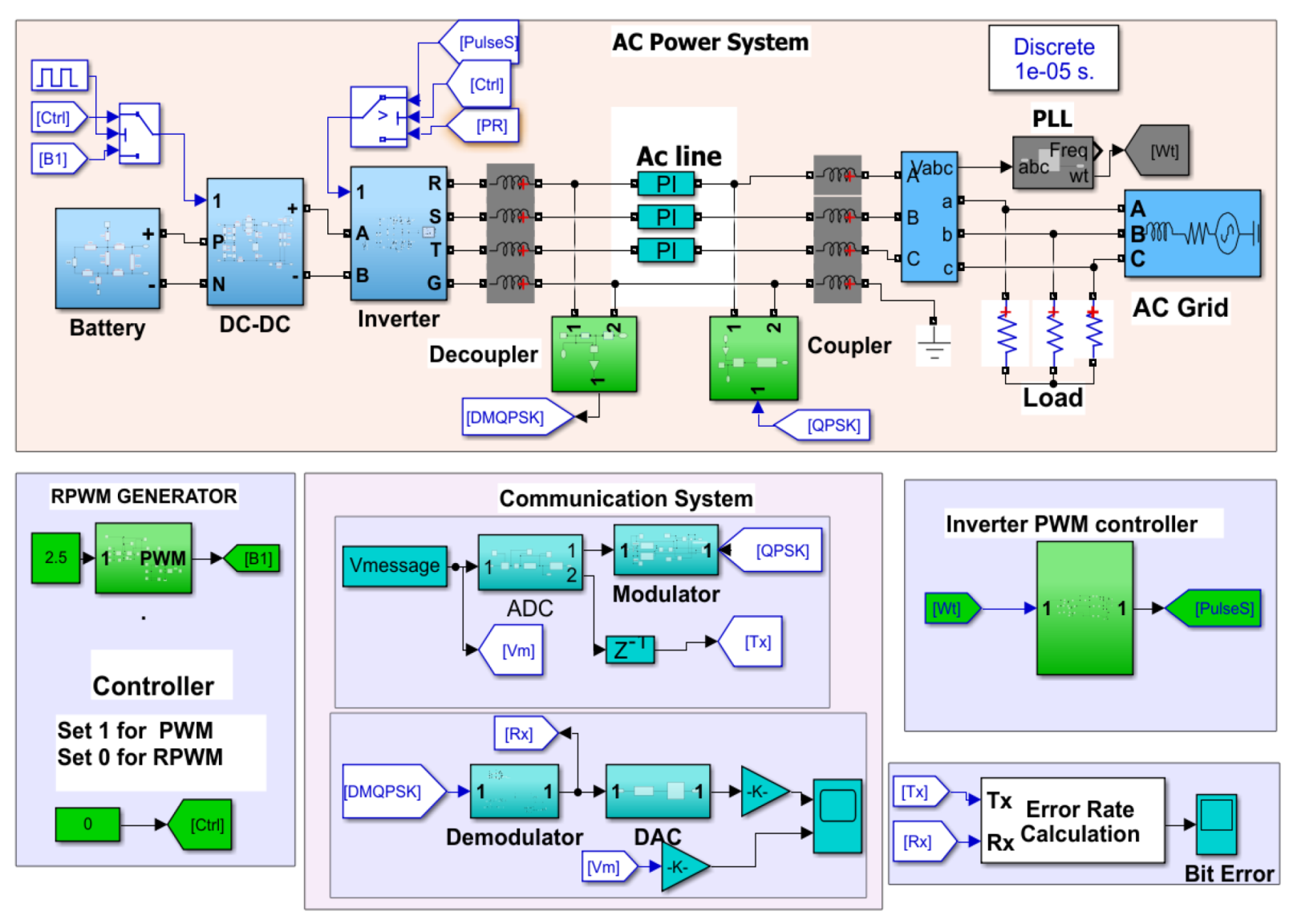
3. Simulation Implementation

MATLAB SIMULINK is used to implement the overall system, as shown in Figure 2. The top box represent the power part (Section 2), the bottom represents the communication system (central box), and the control part, i.e., RPWM generator for the DC-DC converter (bottom-left box) and PWM generators for the inverter (bottom-right box). A detailed description of these models will be provided in the following sections.

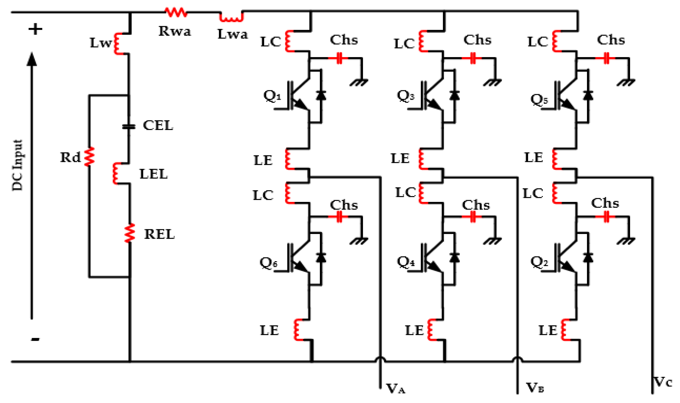
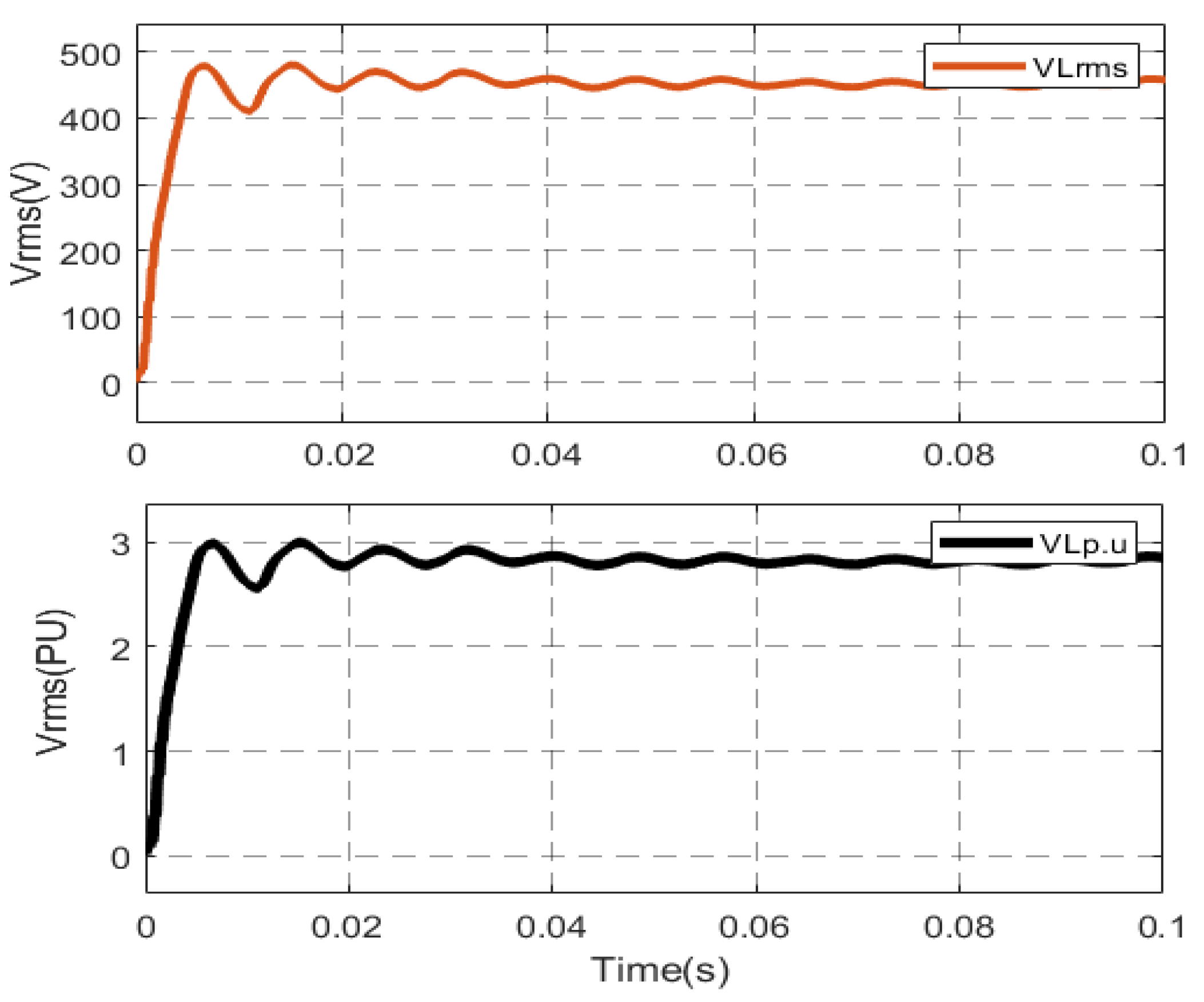
3.1. Circuit Model of the AC System

This subsection provides a detailed description of the circuit models adopted to implement the power part of the system under analysis. The PV panel is represented by an equivalent battery source, as shown in Figure 3a. Parasitic elements are sketched by red color and are used to represent the high-frequency behavior of the battery. In this model, Vdc represents the DC voltage source. The specific topology and numeric values of the red elements are inferred from Reference [22].
Figure 3b shows the circuit model of the implemented DC-DC converter. The DC-DC converter boosts a voltage from 400 V to 800 V with switching frequency of 25 kHz. The parasitic elements are sketched by the red color to represent the high-frequency behavior of the DC-DC converter [23].
Figure 4 shows the inverter model implemented in SIMULINK. The inverter switching frequency is 5 kHz and has a capacity of 10 kW. The parasitic elements of the inverter are shown in red and taken from Reference [24]. The inverter output is synchronized with the AC grid by using a Phase-locked loop (PLL) circuit. The PLL determines the frequency of the AC grid, and this frequency is used to generate the sinusoidal PWM signals for the inverter so that both the inverter and the grid are kept synchronized. Parameters of the value description in Appendix A Table A1.
Short transmission line model is adopted to represent the AC line. The length of this line is assumed as 100 m, and the frequency of interest is 250 kHz (up to 10th order harmonics of the DC-DC converter). Therefore, the three-phase transmission line is approximated by lumped element model considering only the per-unit resistance, inductance, and capacitance of a four-conductor copper wire, each with size of 4 mm 2 [25].
The RPWM scheme is implemented based on randomly varying the triangular carrier wave, as illustrated in Figure 5a, and applied to the DC-DC converter. Two triangular carrier waveforms with the same switching frequency but 180-degree phase shift are compared with the reference signal. Based on the output of a random number generator (randomly providing “0” or “1” as output), the random selector block selects one of the two pulses at a time. As a result, the pulse waveform at the selector output is a mixture of the two pulses, and this results in randomness of the pulse position of the PWM signal.

3.2. Implementation of the Communication System

Key ingredients of the communication systems are:
1.
analog-to-digital conversion (ADC) of the load voltage,
2.
modulation of the digital signal,
3.
coupling/decoupling, and
4.
demodulation.
A detailed description of the implementation of the above features is provided in the next paragraphs.

3.2.1. Analog-to-Digital Conversion

The first step is to measure the load voltage (rms), scale it down to a suitable value and convert the resulting analog signal into an equivalent digital signal. The ADC is implemented first by sampling the analog signal with sampling frequency of 50 kHz. After that, the sampled signal is quantized with the quantization level of 0.4 V. The quantized signal is converted or approximated to the nearest integer value and converted to bits by using the integer to bit converter block available in SIMULINK, as shown in Figure 5b.

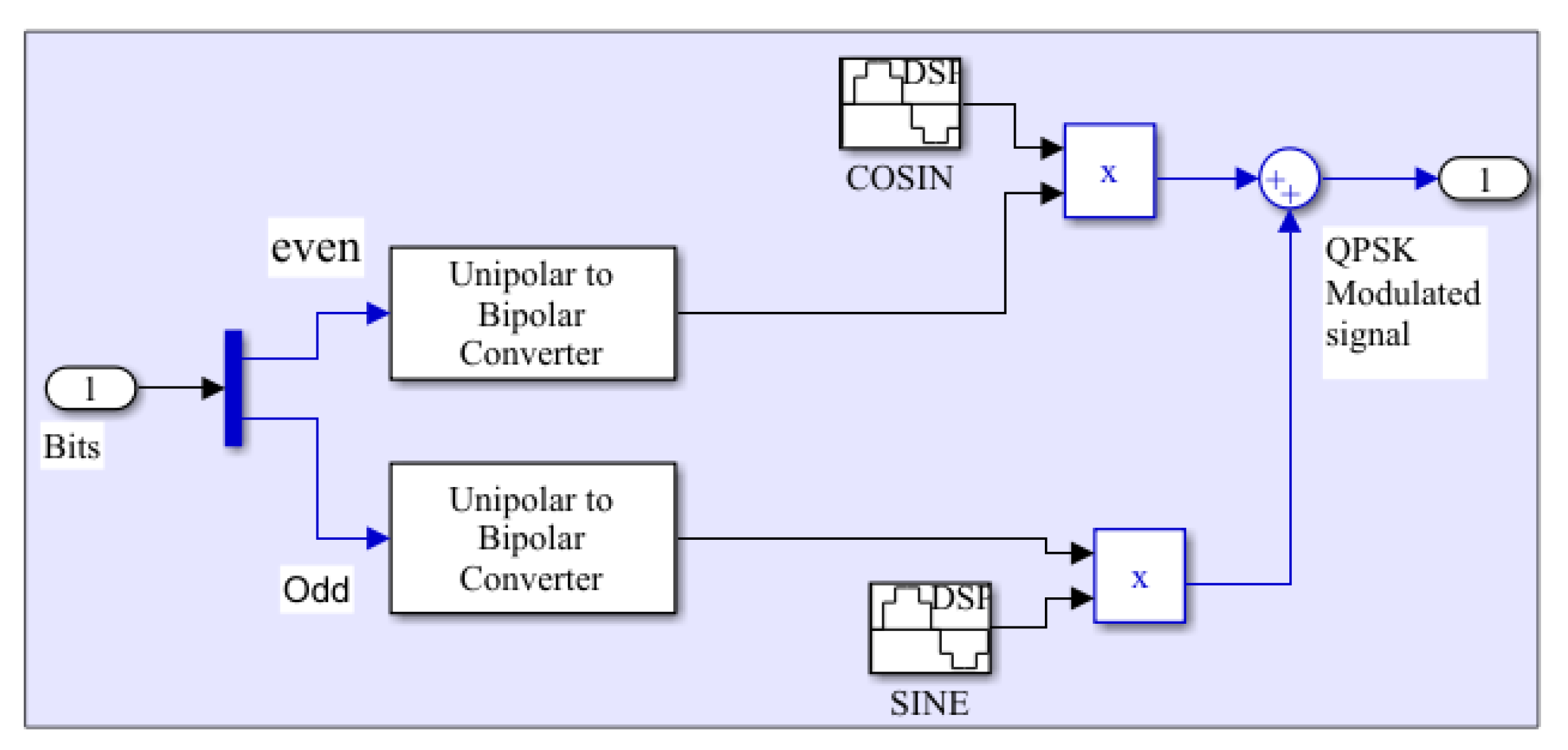
3.2.2. Signal Modulation

The digital signal is then modulated by using QPSK modulator. Two sinusoidal carrier waves in quadrature to each other are used for implementing QPSK. The carriers have a frequency of 5 kHz and have phase difference of 90 degrees. The bits from the ADC are split into odd and even bits and converted from unipolar to bipolar. Then, even bits are multiplied with the in-phase carrier (cosine), and odd bits are multiplied with the quadrature carrier (sine), thus leading to two independent Phase Shift Key (PSK) modulated signals. The two PSK signals are added to obtain the QPSK modulated signal. The overall process of QPSK modulation is implemented in SIMULINK by the schematics shown in Figure 6.

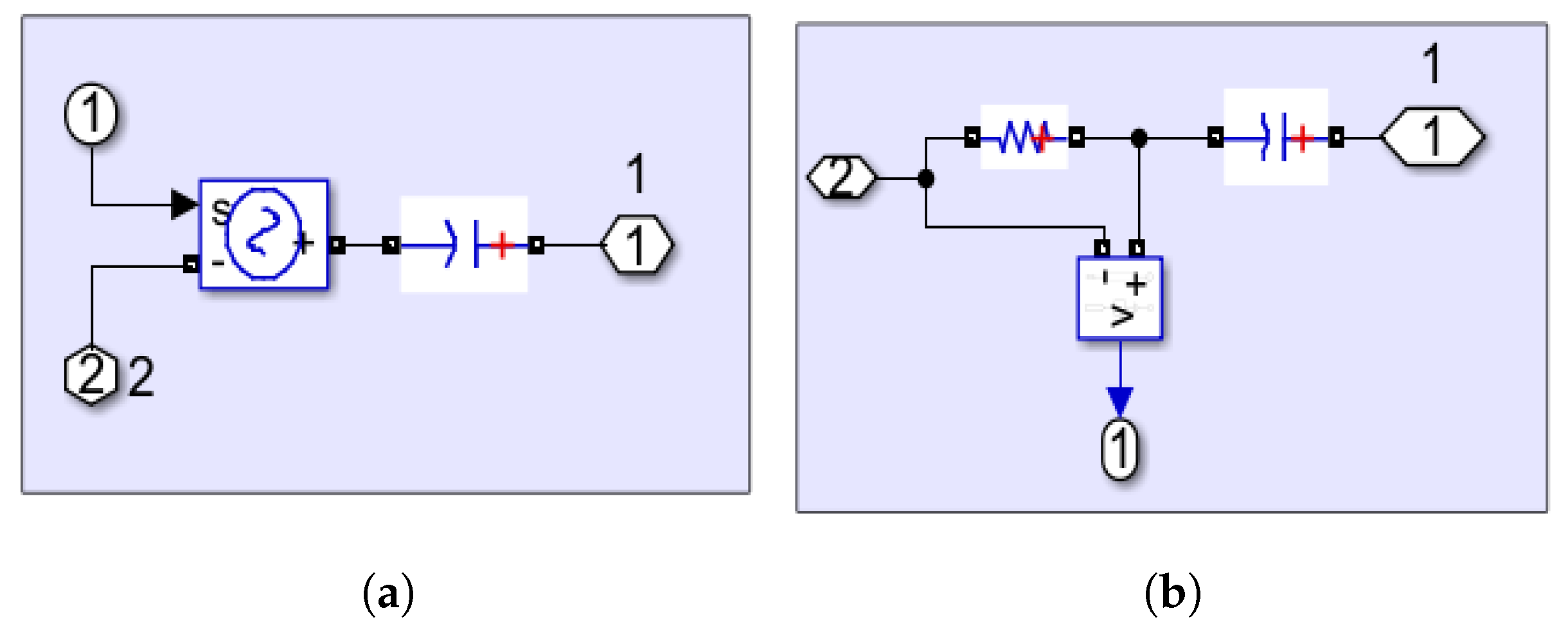
3.2.3. Coupling/Decoupling with the AC Mains

In order to couple the modulated signals through the AC mains, the capacitive coupling/decoupling circuit topology shown in Figure 7a,b are used.

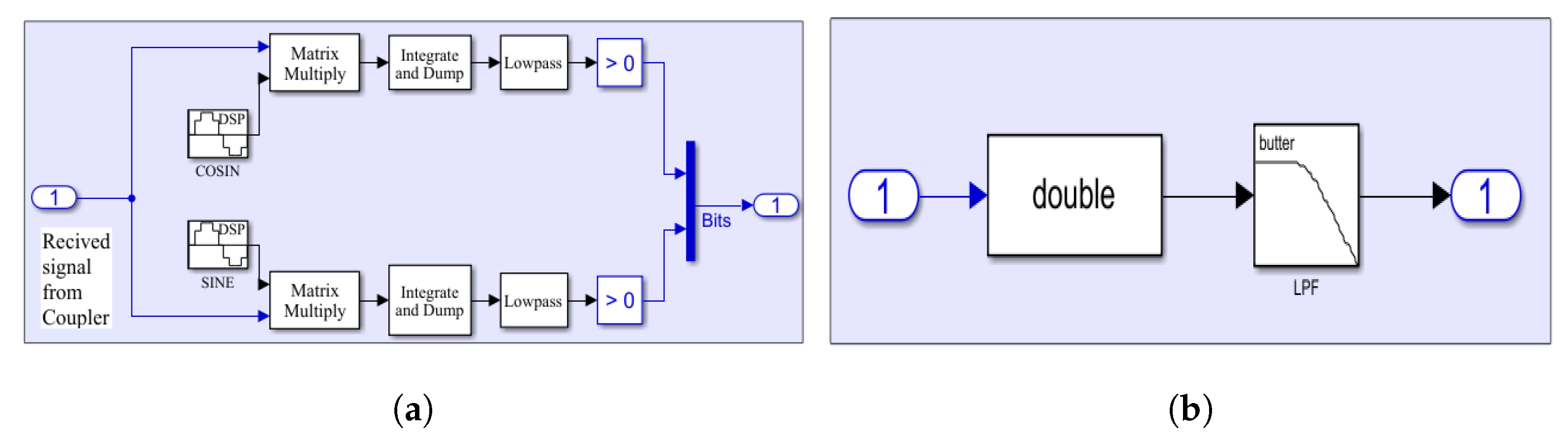
3.2.4. Signal Demodulation

To recover the modulated signal, the signal received from the decoupling circuit, which inherently includes also high frequency noise exiting the converters, is multiplied by the in-phase and in-quadrature carrier waves. This results in the separation of the PSK waves. Each wave passes through an integrator and low pass filter in order to avoid the high frequency components and then compared in the comparator to retrieve the odd and even bits. The obtained bits are then converted into integer numbers. Figure 8a shows the demodulation circuit implemented in SIMULINK.

3.2.5. Digital-to-Analog Conversion

Eventually, the demodulated signal is converted into the corresponding analog signal, to allow the comparison with the original one. To this end, an analog filter with cutoff frequency 100 Hz is used for digital-to-analog conversion, as shown in Figure 8b.
Figure 9 shows the even (brown) and odd (black) bits obtained from the message signal and the resulting QPSK modulated signal (blue). As it can clearly be seen, the QPSK modulated signal has four phase shifts according to the input bit combinations, as expected from QPSK modulator.
Figure 10 illustrates the original message signal (red) and its scaled down version (black) to 3 V. The scaled down signal is transmitted to the PLC system and recovered using the QPSK demodulator.

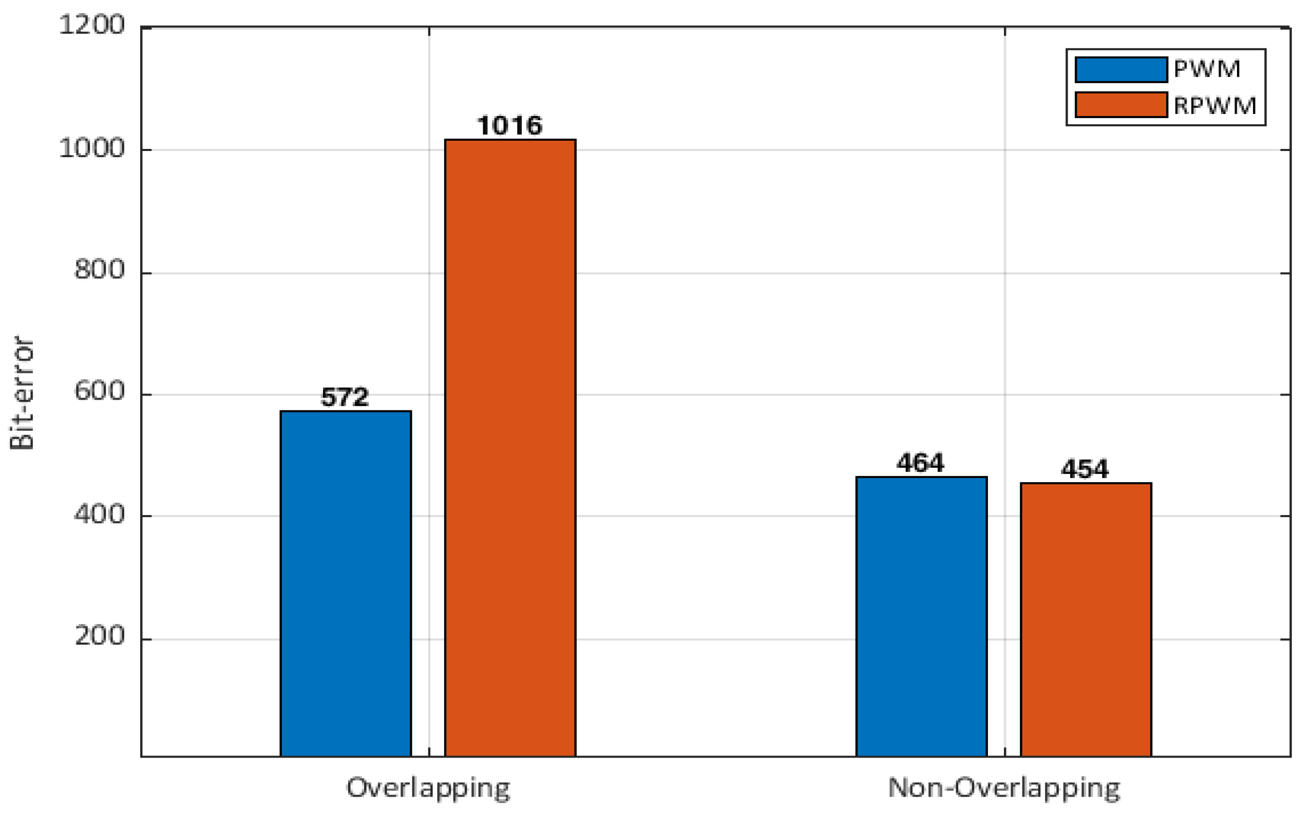
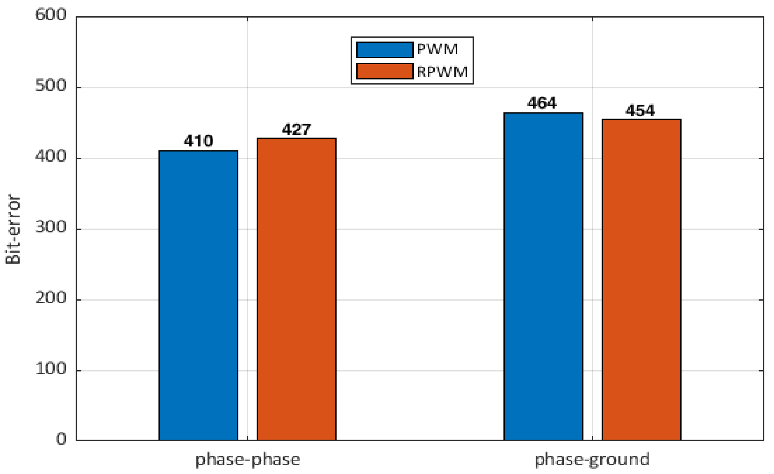
4. Results and Discussion

Power converters in SG generate supra-harmonics in the frequency range 2–150 kHz (there is no standard to limit CEs in this range), which is commonly used by NB-PLC for Smart Metering in SG applications. These emissions may affect the communication system even if the NB-PLC technologies, such as PRIME, G3-PLC, or IEEE 1901.2, allow the use of robust modulation and coding techniques [26,27]. Therefore, among the available EMI mitigation techniques, RPWM is preferable since it is easy to implement and less costly than others, and it is being deployed in many converters, such as inverters (PV systems, wind turbine, electrical vehicle charging, and motor controllers) and DC-DC converters for SG applications. Nevertheless, the influence of RPWM in power grids involving PLC systems still requires investigations. Toward this objective, two test cases will be considered in the following.
In the first test case, the switching frequency of the DC-DC converter is set to 25 kHz, and the modulation frequency of the QPSK modulator to 5 kHz. In this case, RPWM led to an increased bit error rate (1016 errors out of 10,000 samples) with respect to PWM (572 errors), as shown in Figure 11. This is because the peaks of the noise exiting the DC-DC converter do not affect the communication signal, i.e., the frequency of the communication signal does not overlap with the significant noise peaks from the DC-DC converter. This is shown in Figure 12, where the CEs of the DC-DC converter with conventional PWM (blue) and RPWM (red) are shown and compared with the QPSK modulated message signal (black).
It is shown that resorting to RPWM modulation reduces the noise peaks by more than 10 dB compared to the conventional PWM. However, RPWM spreads the noise spectrum, which exhibits higher amplitude than the conventional PWM in the frequency range around 5 kHz (see the black box in Figure 12), with a consequent increase of the interference with the communication signal. This conclusion is in line with the one drawn in Reference [21], where it was proven that RPWM causes more frame error rate than the conventional PWM. However, the RPWM scheme considered in Reference [21] is based on varying the switching frequency of the pulse signal, i.e., the RPWM strategy adopted in that work is different from the one exploited here.
Conversely, the advantages of RPWM modulation can be seen if the switching frequency of the DC-DC converter is reduced to 10 kHz, and the modulation frequency of the QPSK modulator is increased to 15 kHz. Figure 13 shows the frequency spectrum of the noise exiting the DC-DC converter with PWM (blue) and RPWM (red), along with the spectrum of the QPSK modulated signal (black). In this case, the peaks of the noise spectra of the DC-DC converter overlap with the spectral components of the modulated signal. Since the amplitude of the noise peaks is reduced, thanks to RPWM, the bit error rate with RPWM reduces from 1016 to 454, while the bit error rate with PWM reduces from 572 to 464, as shown in Figure 11. It is worth noticing that lower switching frequency, even for PWM, also results in less interference to the communication signal.
To assess the effects that symmetrical/asymmetry of the power cables plays on the PLC system, an additional example is simulated. To this end, the communication signal was connected between two phases rather than one phase and ground as in the previous examples. Figure 14 shows the bit error rate obtained when the communication signal is transmitted between the two phases (the switching frequency of DC-DC converter, in this case, is 25 kHz). The bit error rate drops from 572 to 523 for conventional PWM and from 1016 to 525 for RPWM when the communication signal is connected between the two phases of the AC system. Likewise, Figure 15 shows the bit error rate obtained when the communication signal is transmitted between the two phases (in this case, the switching frequency of the DC-DC converter is 10 kHz). The bit error rate drops from 464 to 410 for conventional PWM and from 454 to 427 for RPWM. This is because connecting the modems between two phases assures better balancing with respect to phase-to-ground connection; hence, signal transmission is affected by less interference.

5. Conclusions

In this paper, the effects of using RPWM to control the switching activity of power electronics converters in power systems involving PLC for advanced meter reading are investigated. To this end, both the power and the communication part of the system were modeled in SIMULINK. The comparison versus traditional PWM is carried out in terms of bit error rate achievable by application of the two modulation schemes. Additionally, the effects of connecting the PLC modems to the power line in different configurations is presented. Based on the obtained results, it is possible to conclude that applying RPWM on the power converter in the PLC system, besides having a significant effect on reducing the CEs, results in less bit error rate compared to the conventional PWM when the modulation frequency of the communication signal and the frequency of the significant peaks of the noise exiting the DC-DC converter are overlapping. Conversely, higher bit error rate will be obtained if the two frequency spectra do not overlap. Results also showed that, to improve the bit error rate, it is preferable to connect the PLC coupling/decoupling networks between two phases of the power line, rather than between a phase and ground, since this assures higher symmetry of the PLC channel. The obtained results will be confirmed by laboratory experiments in the future. Another improvement regards the modeling of the power line by a distributed-parameter circuit model (based on transmission line theory), which will allow accounting for the effects due to propagation on the communication signal.

Author Contributions

Conceptualization, A.H.B., F.G. and P.S.C.; methodology, A.H.B., L.W., F.G., P.S.C. and W.E.S.; software, A.H.B., W.E.S., F.G. and P.S.C.; validation, A.H.B., L.W., F.G., P.S.C., X.L., X.W. and W.E.S.; formal analysis, A.H.B., L.W., F.G., P.S.C., X.L., X.W. and W.E.S.; investigation, A.H.B., L.W., F.G., P.S.C., X.L., X.W., W.E.S., G.S. and S.A.P.; resources, F.G. and S.A.P.; data curation, A.H.B. and L.W.; writing—original draft preparation, A.H.B. and F.G.; writing—review and editing, A.H.B., L.W., F.G., P.S.C., X.L., X.W., W.E.S., G.S. and S.A.P.; visualization, F.G., W.E.S. and P.S.C.; supervision, F.G., P.S.C., G.S. and S.A.P.; project administration, F.G.; funding acquisition, F.G. All authors have read and agreed to the published version of the manuscript.

Funding

This project has received funding from the European Union’s Horizon 2020 research and innovation program under the Marie Skłodowska-Curie grant agreement No 812753.

Conflicts of Interest

The authors declare no conflict of interest.

Appendix A

Table A1. Parameters of the inverter model in Figure 4.
ParameterValueDescription
Lw10 nHExternal wire inductance
CEL1500 μ FNominal capacitance
LEL30 nHInternal series inductance
REL40 m Ω Internal series resistance
Rd1 k Ω Discharging resistance
Rwa3.9 m Ω Stray resistance
Lwa0.36 μ HStray inductance
Cs0.33 μ FNominal capacitor
Ls30 nHInternal series inductance
Rs30 m Ω Internal series resistance
LC40 nHCollector stray inductance
LE40 nHEmitter stray inductance
Chs280 pFStray capacitor between IGBT and heatsink

References

  1. Kabalci, Y. A survey on smart metering and smart grid communication. Renew. Sustain. Energy Rev. 2016, 57, 302–318. [Google Scholar] [CrossRef]
  2. Ancillotti, E.; Bruno, R.; Conti, M. The role of communication systems in smart grids: Architectures, technical solutions and research challenges. Comput. Commun. 2013, 36, 1665–1697. [Google Scholar] [CrossRef] [Green Version]
  3. Uribe-Pérez, N.; Angulo, I.; De la Vega, D.; Arzuaga, T.; Fernández, I.; Arrinda, A. Smart Grid Applications for a Practical Implementation of IP over Narrowband Power Line Communications. Energies 2017, 10, 1782. [Google Scholar] [CrossRef] [Green Version]
  4. Sendin, A.; Simon, J.; Urrutia, I.; Berganza, I. PLC deployment and architecture for Smart Grid applications in Iberdrola. In Proceedings of the 18th IEEE International Symposium on Power Line Communications and Its Applications, Glasgow, UK, 30 March–2 April 2014; pp. 173–178. [Google Scholar] [CrossRef]
  5. Ngcobo, T.; Ghayoor, F. Study the Topology Effect on a G3-PLC based AMI Network. In Proceedings of the 2019 Southern African Universities Power Engineering Conference/Robotics and Mechatronics/Pattern Recognition Association of South Africa (SAUPEC/RobMech/PRASA), Bloemfontein, South Africa, 28–30 January 2019; pp. 629–633. [Google Scholar] [CrossRef]
  6. de Arquer Fernández, P.; Fernández, M.Á.F.; Candás, J.L.C.; Arboleya, P.A. An IoT open source platform for photovoltaic plants supervision. Int. J. Electr. Power Energy Syst. 2021, 125, 106540. [Google Scholar] [CrossRef]
  7. González, I.; Calderón, A.J.; Portalo, J.M. Innovative Multi-Layered Architecture for Heterogeneous Automation and Monitoring Systems: Application Case of a Photovoltaic Smart Microgrid. Sustainability 2021, 13, 2234. [Google Scholar] [CrossRef]
  8. Tightiz, L.; Yang, H. A Comprehensive Review on IoT Protocols’ Features in Smart Grid Communication. Energies 2020, 13, 2762. [Google Scholar] [CrossRef]
  9. Ikpehai, A.; Adebisi, B.; Rabie, K.M. Broadband PLC for Clustered Advanced Metering Infrastructure (AMI) Architecture. Energies 2016, 9, 569. [Google Scholar] [CrossRef]
  10. Khan, M.S.; Ahmed, T.; Aziz, I.; Alam, F.B.; Bhuiya, M.S.U.; Alam, M.J.; Chakma, R.; Mahtab, S.S. PLC Based Energy-Efficient Home Automation System with Smart Task Scheduling. In Proceedings of the 2019 IEEE Sustainable Power and Energy Conference (iSPEC), Beijing, China, 21–23 November 2019; pp. 35–38. [Google Scholar] [CrossRef]
  11. Barmada, S.; Raugi, M.; Tucci, M.; Maryanka, Y.; Amrani, O. PLC systems for electric vehicles and Smart Grid applications. In Proceedings of the 2013 IEEE 17th International Symposium on Power Line Communications and Its Applications, Johannesburg, South Africa, 24–27 March 2013; pp. 23–28. [Google Scholar] [CrossRef]
  12. Grassi, F.; Pignari, S.A.; Wolf, J. Channel Characterization and EMC Assessment of a PLC System for Spacecraft DC Differential Power Buses. IEEE Trans. Electromagn. Compat. 2011, 53, 664–675. [Google Scholar] [CrossRef]
  13. Loschi, H.; Lezynski, P.; Smolenski, R.; Nascimento, D.; Sleszynski, W. FPGA-Based System for Electromagnetic Interference Evaluation in Random Modulated DC/DC Converters. Energies 2020, 13, 2389. [Google Scholar] [CrossRef]
  14. Tse, K.K.; -Chung, H.S.; Huo, S.Y.; So, H.C. Analysis and spectral characteristics of a Spread-Spectrum technique for conducted EMI suppression. IEEE Trans. Power Electron. 2000, 15, 399–410. [Google Scholar] [CrossRef] [Green Version]
  15. Liaw, C.M.; Lin, Y.M.; Wu, C.H.; Hwu, K.I. Analysis, Design, and Implementation of a Random Frequency PWM Inverter. IEEE Trans. Power Electron. 2000, 15, 843–854. [Google Scholar] [CrossRef]
  16. Chen, C.Q.X.; Qiu, Y. Carrier-Based Randomized Pulse Position Modulation of an Indirect Matrix Converter for Attenuating the Harmonic Peaks. IEEE Trans. Ind. Appl. 2013, 28, 3539–3548. [Google Scholar]
  17. Kabalci, E.; Kabalci, Y.; Develi, I. Modelling and analysis of a power line communication system with QPSK modem for renewable smart grids. Int. J. Electr. Power Energy Syst. 2012, 34, 19–28. [Google Scholar] [CrossRef]
  18. El Sayed, W.; Loschi, H.; Smolenski, R.; Lezynski, P.; Lok, C.L. Performance Evaluation of the Effect of Power Converters Modulation on Power line Communication. In Proceedings of the Sterowanie w Energoelektronice i Napędzie Elektrycznym (SENE), Łódź, Poland, 20–22 November 2019. [Google Scholar]
  19. Bolognani, S.; Peretti, L.; Sgarbossa, L.; Zigliotto, M. Improvements in Power Line Communication Reliability for Electric Drives by Random PWM Techniques. In Proceedings of the IECON 2006–32nd Annual Conference on IEEE Industrial Electronics, Paris, France, 6–10 November 2006; pp. 2307–2312. [Google Scholar] [CrossRef]
  20. Musolino, F.; Crovetti, P.S. Interference of Spread-Spectrum Modulated Disturbances on Digital Communication Channels. IEEE Access 2019, 7, 158969–158980. [Google Scholar] [CrossRef]
  21. Sayed, W.E.; Lezynski, P.; Smolenski, R.; Moonen, N.; Crovetti, P.; Thomas, D.W.P. The Effect of EMI Generated from Spread-Spectrum-Modulated SiC-Based Buck Converter on the G3-PLC Channel. Electronics 2021, 10, 1416. [Google Scholar] [CrossRef]
  22. Reuter, M.; Friedl, T.; Tenbohlen, S.; Kohler, W. Emulation of conducted emissions of an automotive inverter for filter development in HV networks. In Proceedings of the 2013 IEEE International Symposium on Electromagnetic Compatibility, Denver, CO, USA, 5–9 August 2013; pp. 236–241. [Google Scholar]
  23. Beshir, A.H. Design and Development of 20 kW Bidirectional dc-dc Converter Using Silicon Carbide Technology. Master’s Thesis, Department of EECS, University of Oviedo, Oviedo, Spain, 2019. Available online: https://digibuo.uniovi.es/dspace/bitstream/handle/10651/52604/TFM_AbduselamHamidBeshir.pdf;jsessionid=728F01322727C27B03F57E9FD4F3B1F7?sequence=3 (accessed on 1 December 2020).
  24. Grandi, G.; Casadei, D.; Reggiani, U. Common- and differential-mode HF current components in AC motors supplied by voltage source inverters. IEEE Trans. Power Electron. 2004, 19, 16–24. [Google Scholar] [CrossRef]
  25. Datasheet Stock No: 811-1448 RS Pro Red Tri-Rated Cable, PVC. Available online: http://static6.arrow.com/aropdfconversion/92d7c9b42b27b406d3fa7b241b5395b6a3c10155/pgurl_8111448.pdf (accessed on 1 December 2020).
  26. Electromagnetic Interference Between Electrical Equipment/Systems in the Frequency Range Below 150 khz, Standard CENELEC SC 205A. 2015. Available online: https://standards.iteh.ai/catalog/standards/clc/f2fe2993-4360-4bee-9cce-1cf000ebb2da/clc-tr-50627-2015 (accessed on 1 December 2020).
  27. Uribe-Pérez, N.; Angulo, I.; Hernández-Callejo, L.; Arzuaga, T.; De la Vega, D.; Arrinda, A. Study of Unwanted Emissions in the CENELEC-A Band Generated by Distributed Energy Resources and Their Influence over Narrow Band Power Line Communications. Energies 2016, 9, 1007. [Google Scholar] [CrossRef] [Green Version]
Figure 1. Block diagram of the PLC system under analysis.
Electronics 10 02979 g001
Figure 2. SIMULINK schematics of the PLC system under analysis.
Electronics 10 02979 g002
Figure 3. Implemented SIMULINK model of (a) battery, (b) DC-DC converter (parasitics elements are outlined in red).
Electronics 10 02979 g003
Figure 4. Circuit model of the inverter (parasitics elements are outlined in red).
Electronics 10 02979 g004
Figure 5. SIMULINK implementation of the (a) RPWM control system; and (b) the analog-to-digital converter.
Electronics 10 02979 g005
Figure 6. QPSK modulator circuit implemented in SIMULINK.
Electronics 10 02979 g006
Figure 7. Capacitive (a) coupling and (b) decoupling networks implemented in SIMULINK.
Electronics 10 02979 g007
Figure 8. SIMULINK implementation of the (a) QPSK demodulator and (b) the digital-to-analog converter.
Electronics 10 02979 g008
Figure 9. Binary bits and QPSK modulated signal waveforms.
Electronics 10 02979 g009
Figure 10. Message signal: (top) original signal, (bottom) scaled down signal.
Electronics 10 02979 g010
Figure 11. Bit error rate: PWM (blue) versus RPWM (orange).
Electronics 10 02979 g011
Figure 12. Voltage harmonics at the DC-DC converter output: PWM versus RPWM (25 kHz switching frequency) and frequency spectrum of QPSK modulated signal. The x-axis is in logarithmic scale.
Electronics 10 02979 g012
Figure 13. Voltage harmonics at the output of the DC-DC converter: PWM versus RPWM (10 kHz switching frequency) and frequency spectrum of QPSK modulated signal. The x-axis is in logarithmic scale.
Electronics 10 02979 g013
Figure 14. Bit error rate with coupling/decoupling networks connected between two phases or between one phase and ground (25 kHz switching frequency).
Electronics 10 02979 g014
Figure 15. Bit error rate with coupling/decoupling networks connected between two phases or between one phase and ground (10 kHz switching frequency).
Electronics 10 02979 g015
Publisher’s Note: MDPI stays neutral with regard to jurisdictional claims in published maps and institutional affiliations.

