
An All-Textile Dual-Band Antenna for BLE and LoRa Wireless Communications


Abstract
:1. Introduction
2. Antenna Design
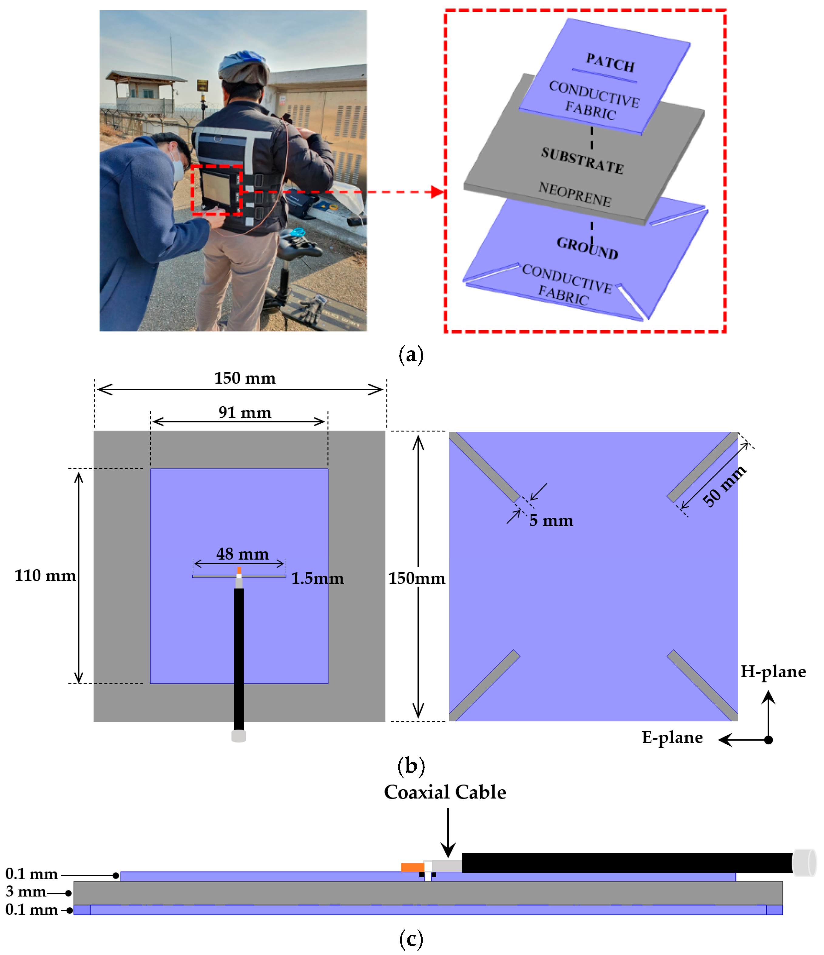
2.1. Materials
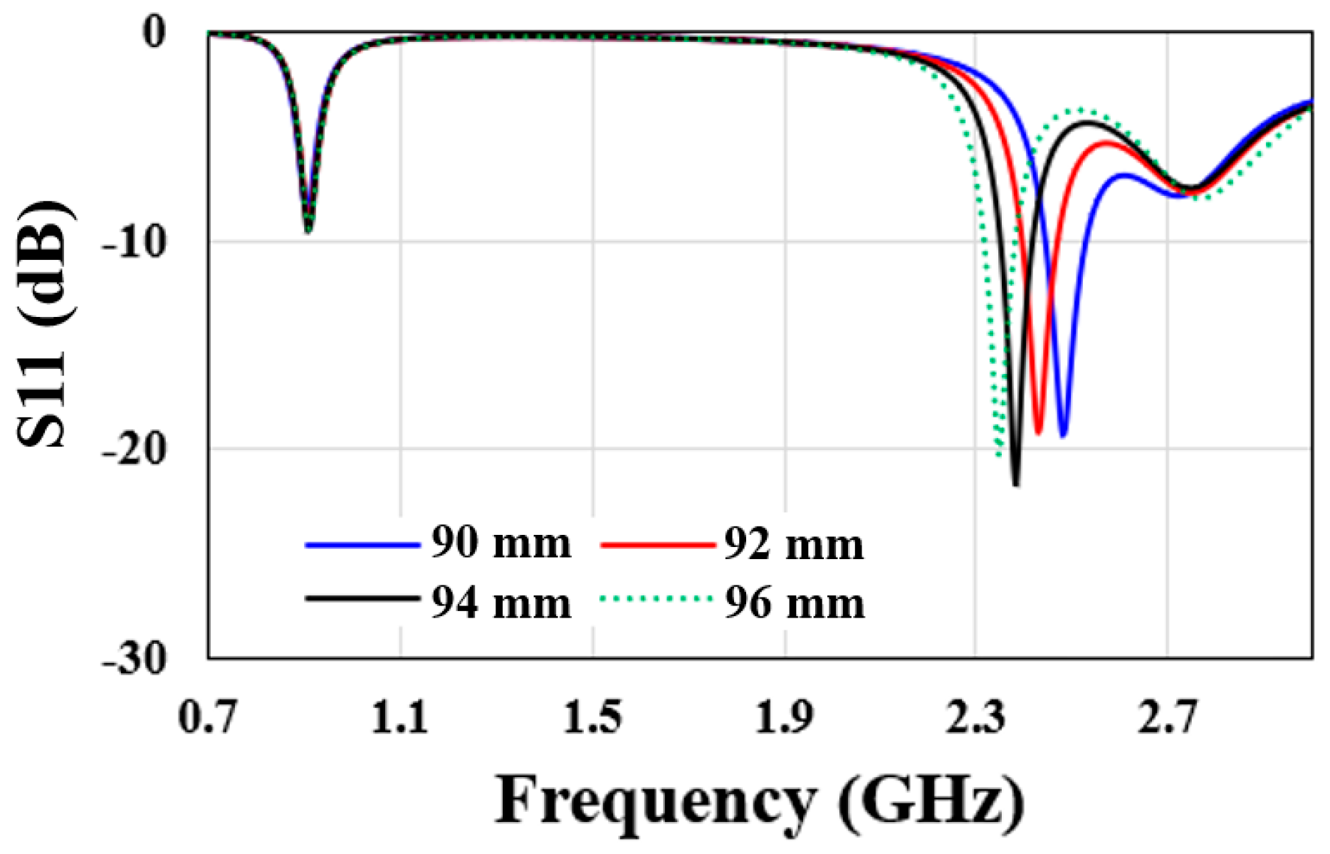
2.2. Design Structure
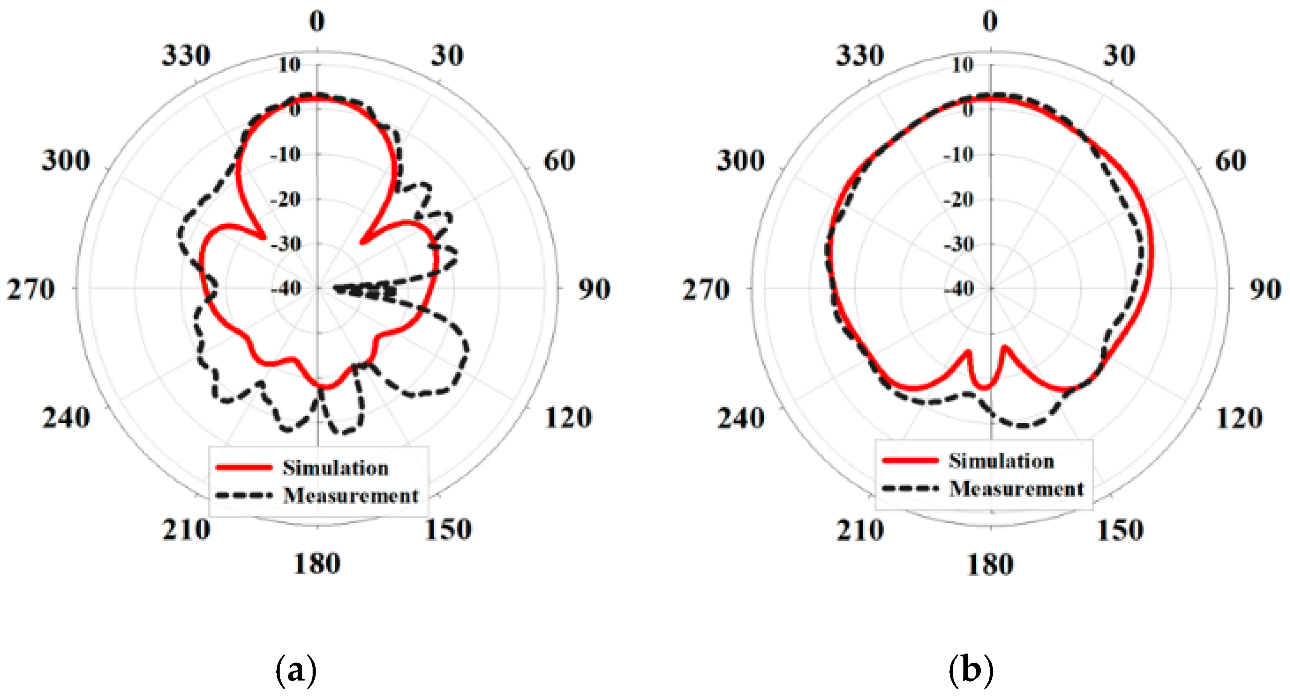
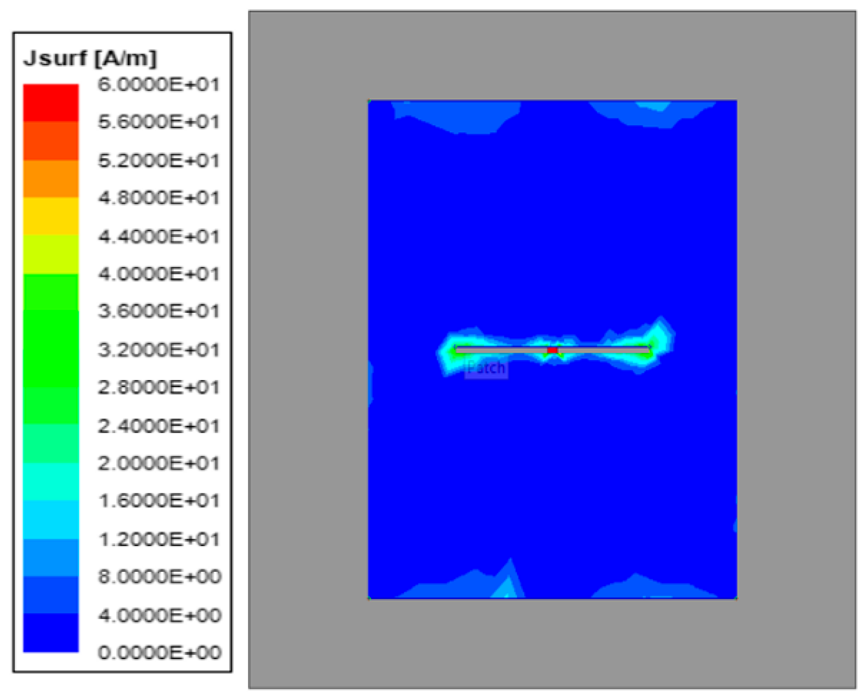
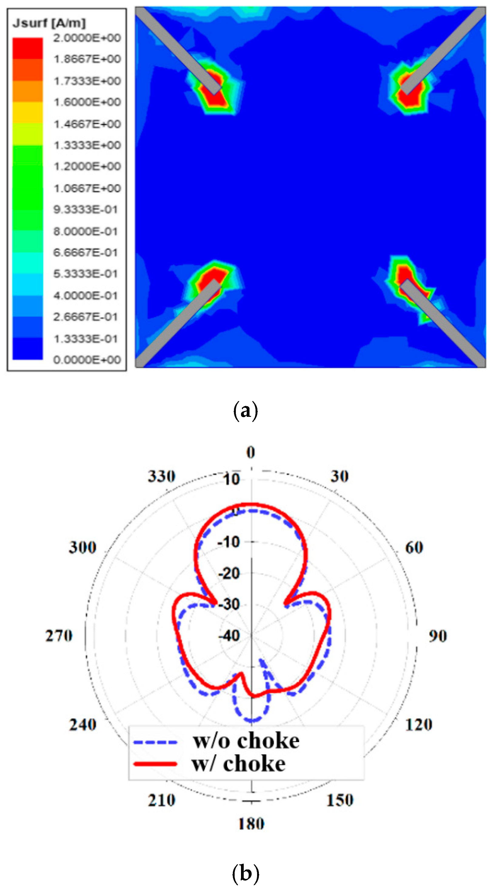
2.3. Backlobe Reduction Technique
3. Antenna Fabrication and Measurement
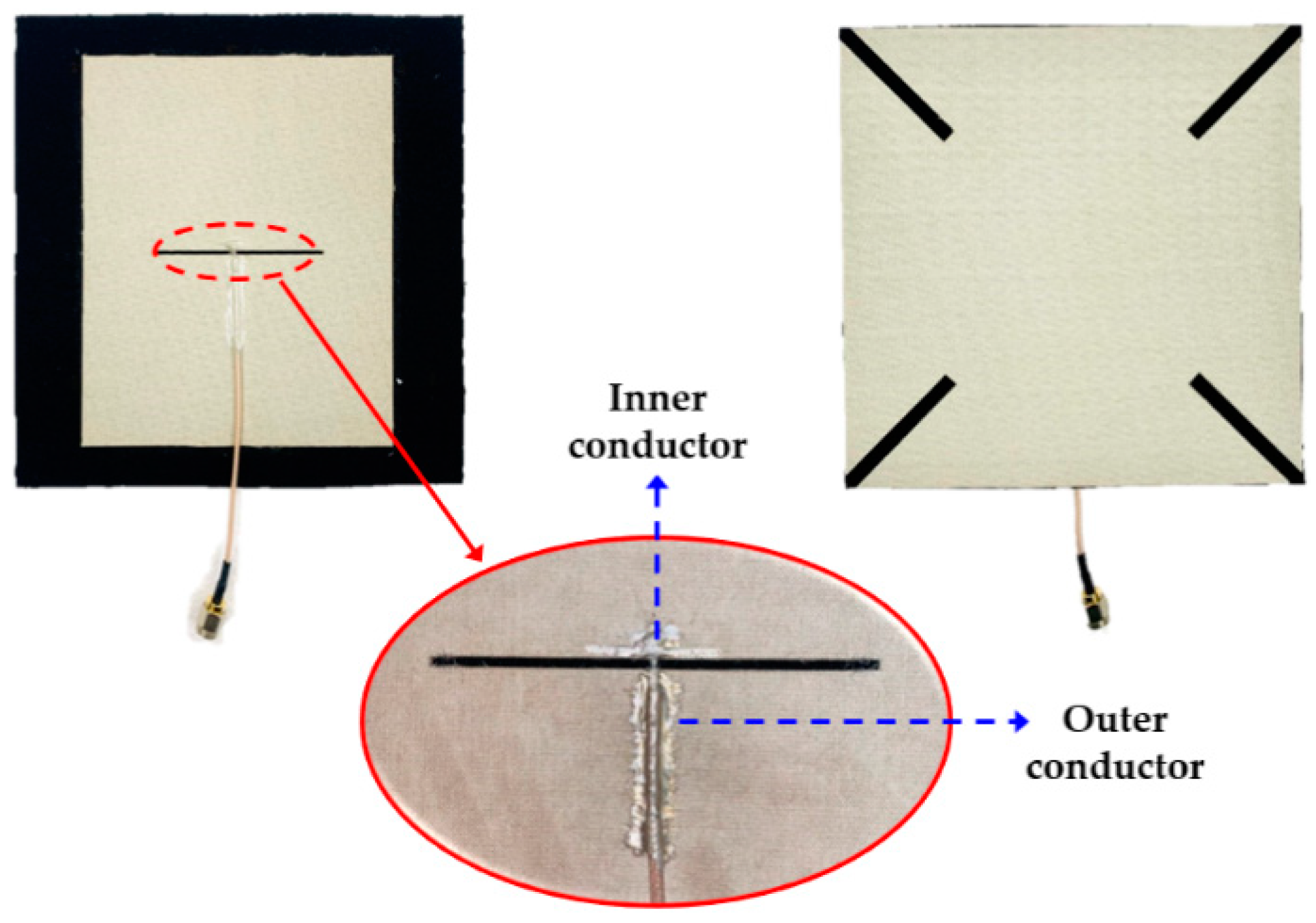
3.1. Antenna Fabrication
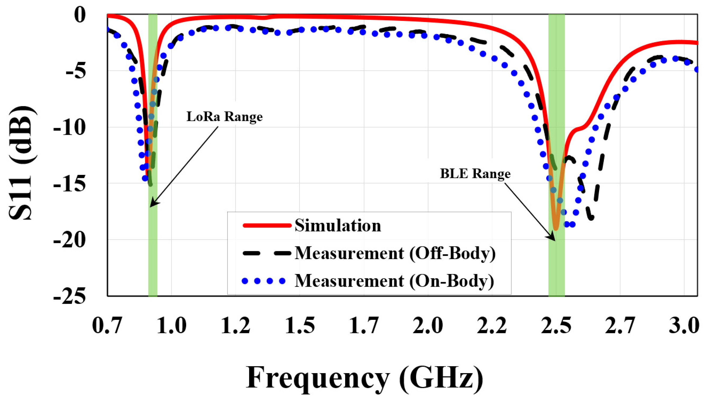
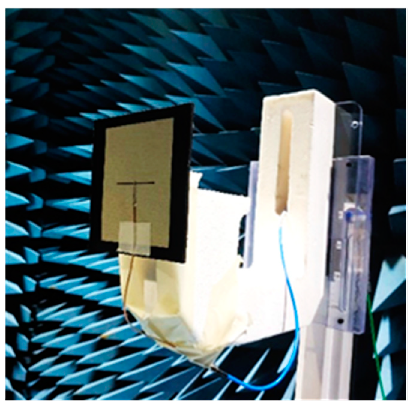
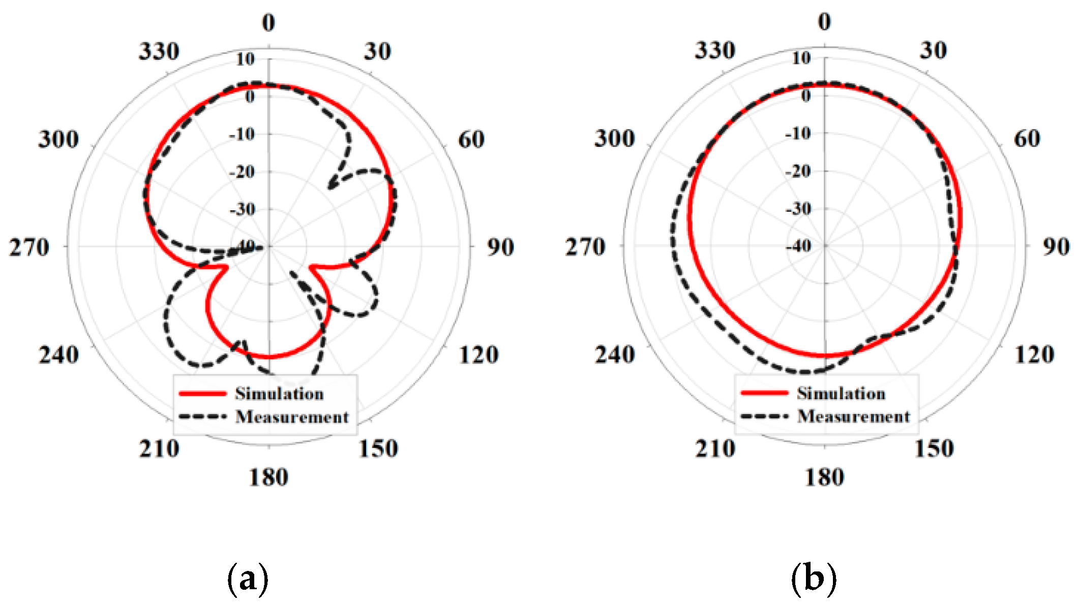
3.2. Antenna Measurement and Discussion
4. Conclusions
Author Contributions
Funding
Conflicts of Interest
References
- GlobeNewswire: Research & Markets. Available online: https://www.globenewswire.com/ (accessed on 5 January 2021).
- Yilmaz, E.; Kasilingam, D.P.; Notaros, B.M. Performance analysis of wearable microstrip antennas with low-conductivity materials. In Proceedings of the 2008 IEEE Antennas and Propagation Society International Symposium, San Diego, CA, USA, 5–12 July 2008. [Google Scholar]
- Loss, C.; Goncalves, R.; Lopes, C.; Pinho, P.; Salvado, R. Smart Coat with a Fully-Embedded Textile Antenna for IoT Applications. Sensors 2016, 16, 938. [Google Scholar] [CrossRef] [PubMed]
- Aprilliyani, R.; Dzagbletey, P.A.; Lee, J.H.; Jang, M.J.; So, J.-H.; Chung, J.-Y. Effects of Textile Weaving and Finishing Processes on Textile-Based Wearable Patch Antennas. IEEE Access 2020, 8, 63295–63301. [Google Scholar] [CrossRef]
- Chin, K.-S.; Wu, C.-S.; Shen, C.-L.; Tsai, K.-C. Designs of Textile Antenna Arrays for Smart Clothing Applications. Autex Res. J. 2018, 18, 295–307. [Google Scholar] [CrossRef] [Green Version]
- Chahat, N.; Zhadobov, M.; Coq, L.L.; Sauleau, R. Wearable Endfire Textile Antenna for On-Body Communications at 60 GHz. IEEE Antennas Wirel. Propag. Lett. 2012, 11, 799–802. [Google Scholar] [CrossRef]
- Potey, P.M.; Tuckley, K. Design of wearable textile antenna for low back radiation. J. Electromagn. Waves Appl. 2019, 34, 235–245. [Google Scholar] [CrossRef]
- Torre, P.V.; Agneessens, S.; Verhaevert, J.; Rogier, H. Body-worn channel characterization unit for the 868 MHz band. In Proceedings of the 12th European Conference on Antennas and Propagation (EuCAP 2018), London, UK, 9–13 April 2018; pp. 1–5. [Google Scholar]
- Rais, N.H.M.; Soh, P.J.; Malek, M.F.A.; Vandenbosch, G.A. Dual-Band Suspended-Plate Wearable. IEEE Antennas Wirel. Propag. Lett. 2013, 12, 583–586. [Google Scholar] [CrossRef]
- Le, T.T.; Yun, T.-Y. Miniaturization of a Dual-Band Wearable Antenna for WBAN Applications. IEEE Antennas Wirel. Propag. Lett. 2020, 19, 1452–1456. [Google Scholar] [CrossRef]
- Simorangkir, R.B.V.B.; Yang, Y.; Matekovits, L.; Esselle, K.P. Dual-Band Dual-Mode Textile Antenna on PDMS. IEEE Antennas Wirel. Propag. Lett. 2017, 16, 677–680. [Google Scholar] [CrossRef]
- Bhattacharjee, S.; Maity, S.; Chaudhuri, S.R.B.; Mitra, M. A Compact Dual-Band Dual-Polarized Omnidirectional Antenna for On-Body Applications. IEEE Trans. Antennas Propag. 2019, 67, 5044–5053. [Google Scholar] [CrossRef]
- Wang, K.; Li, J. Jeans Textile Antenna for Smart Wearable Antenna. In Proceedings of the 2018 12th International Symposium on Antennas, Propagation and EM Theory (ISAPE), Hangzhou, China, 3–6 December 2018; pp. 1–3. [Google Scholar]
- Yan, S.; Soh, P.J.; Vandenbosch, G.A.E. Wearable Dual-Band Magneto-Electric Dipole Antenna. IEEE Trans. Antennas Propag. 2015, 63, 4165–4169. [Google Scholar] [CrossRef]
- Yan, S.; Soh, P.J.; Vandenbosch, G.A.E. Low-Profile Dual-Band Textile Antenna with Artificial Magnetic Conductor. IEEE Trans. Antennas Propag. 2014, 62, 6487–6490. [Google Scholar] [CrossRef]
- Lee, J.H.; Dzagbletey, P.A.; Jang, M.; Chung, J.-Y.; So, J.-H. Flat Yarn Fabric Substrates for Screen-Printed Conductive Textiles. Adv. Eng. Mater. 2020, 22, 2000722. [Google Scholar] [CrossRef]
- Hoagland, H.; Morrow, B. Using rainwear as switching jackets: A reasonable solution for electric arc exposure. IEEE Trans. Ind. Appl. 2000, 36, 1241–1246. [Google Scholar] [CrossRef]
- Antenna and Accessories for Wireless Network. Available online: https://interline.pl/Information-and-Tips/LONG-RANGE-IOT (accessed on 10 May 2021).
- Ansys Inc. Ansys HFSS; Ansys Inc.: Canonsburg, PA, USA, 2021. [Google Scholar]
- Henkel-Adhesive Technologies Loctite Edag 479SS E&C: Technical Datasheet. Available online: https://www.henkel-adhesives.com/kr/en/product/inks-_-coatings/loctite_edag_479ssec.html (accessed on 21 January 2021).
- Kong, D.K.; Kim, J.; Woo, D.; Yoon, Y.J. Broadband Modified Proximity Coupled Patch Antenna with Cavity-Backed Configuration. J. Electromagn. Eng. Sci. 2021, 21, 8–14. [Google Scholar] [CrossRef]
- Ali, A.; Wang, H.; Yun, Y.; Lee, J.; Park, I. Compact Slot Antenna Integrated with a Photovoltaic Cell. J. Electromagn. Eng. Sci. 2020, 20, 248–253. [Google Scholar] [CrossRef]
- Balanis, C.A. Antenna Theory: Analysis and Design, 4th ed.; John Wiley & Sons, Inc.: Hoboken, NJ, USA, 2016. [Google Scholar]
- Lim, W.-G.; Jang, H.S.; Yu, J.W. New method for back lobe suppression of microstrip patch antenna for GPS. In Proceedings of the 40th European Microwave Conference, Paris, France, 28–30 September 20. [CrossRef]


| References | Substrate Material | Size (λg3) * | Feed Method |
|---|---|---|---|
| [9] | Polyurethane foam (εr = 1.07, tan δ = --) | 0.68 × 0.5 × 0.042 | Bottom-fed with SMA-C ** |
| [10] | Rogers RT/Duroid 5880 (εr = 2.2, tan δ = 0.0009) | 0.23 × 0.15 × 0.006 | Side-fed with SMA-C |
| [13] | Jeans (εr = 1.54, tan δ = --) | 0.47 × 0.16 × -- | Side-fed with SMA-C |
| [14] | Felt (εr = 1.3, tan δ = 0.044) | 0.93 × 0.93 × 0.057 | Bottom-fed with SMA-C |
| [15] | Felt (εr = 1.2, tan δ = 0.044) | 0.90 × 0.90 × 0.031 | Bottom-fed with SMA-C |
| This Work | Neoprene (εr = 1.95, tan δ = 0.02) | 0.61 × 0.61 × 0.012 | Side-fed without SMA-C |
Publisher’s Note: MDPI stays neutral with regard to jurisdictional claims in published maps and institutional affiliations. |
© 2021 by the authors. Licensee MDPI, Basel, Switzerland. This article is an open access article distributed under the terms and conditions of the Creative Commons Attribution (CC BY) license (https://creativecommons.org/licenses/by/4.0/).
Share and Cite
Ibrahim, N.F.; Dzabletey, P.A.; Kim, H.; Chung, J.-Y. An All-Textile Dual-Band Antenna for BLE and LoRa Wireless Communications. Electronics 2021, 10, 2967. https://doi.org/10.3390/electronics10232967
Ibrahim NF, Dzabletey PA, Kim H, Chung J-Y. An All-Textile Dual-Band Antenna for BLE and LoRa Wireless Communications. Electronics. 2021; 10(23):2967. https://doi.org/10.3390/electronics10232967
Chicago/Turabian StyleIbrahim, Nur Fatihah, Philip Ayiku Dzabletey, Hyoungsoo Kim, and Jae-Young Chung. 2021. "An All-Textile Dual-Band Antenna for BLE and LoRa Wireless Communications" Electronics 10, no. 23: 2967. https://doi.org/10.3390/electronics10232967
APA StyleIbrahim, N. F., Dzabletey, P. A., Kim, H., & Chung, J.-Y. (2021). An All-Textile Dual-Band Antenna for BLE and LoRa Wireless Communications. Electronics, 10(23), 2967. https://doi.org/10.3390/electronics10232967