Abstract
This paper proposes a small-slot antenna system (50 mm × 9 mm × 2.7 mm) for 4 × 4 multiple-input multiple-output (MIMO) on smart glasses devices. The antenna is set on the plastic temple, and the inverted F antenna radiates through the slot in the ground plane of the sputtered copper layer outside the temple. Two symmetrical antennas and slots on the same temple and series capacitive elements enhance the isolation between the two antenna ports. When both temples are equipped with the proposed antennas, 4 × 4 MIMO transmission can be achieved. The antenna substrate is made of polycarbonate (PC), and its thickness is 2.7 mm . According to the actual measurement results, this antenna has two working frequency bands when the reflection coefficient is lower than −10dB, its working frequency bandwidth at 4.58–5.72 GHz and 6.38–7.0 GHz. The proposed antenna has a peak gain of 4.3 dBi and antenna efficiency of 85.69% at 5.14 GHz. In addition, it also can obtain a peak gain of 3.3 dBi and antenna efficiency of 82.78% at 6.8 GHz. The measurement results show that this antenna has good performance, allowing future smart eyewear devices to be applied to Wi-Fi 5G (5.18–5.85 GHz) and Wi-Fi 6e (5.925–7.125 GHz).
1. Introduction
Smart wearable devices that are compact, lightweight, and ergonomic are quickly becoming mainstream. With the development of communication technology, smart glasses have gradually received widespread attention, such as the Google smart glasses in 2012, smart goggles Form Swim Goggles in 2019, and the recent Facebook smart glasses in 2021. The antenna design specifications of smart glasses mostly use Bluetooth and Wi-Fi wireless communication for indoor communication and entertainment. Moreover, they communicate with mobile phones and wearable devices via Bluetooth [1,2,3]. However, with the rapid development of smart glasses research, smart glasses devices will no longer only use Bluetooth or Wi-Fi antenna technology, such as a WiGig array module antenna design on the frame [4] or LTE multi-band antenna design on the temple [5].
At present, there are various types of antennas in smart wearable devices and smartphones. These devices usually demand ultra-wideband (UWB) operation. Due to the limited antenna design space, slot antennas or microstrip antennas are the best choice for these work environments [6,7,8,9,10,11,12]. In recent years, articles on the configuration of slot antennas for wireless communication products have emerged. For example, a notebook device uses the shaft block to design the slot antenna to produce a 2 × 2 MIMO antenna system for low frequencies of 700–900 MHz and high frequencies of 1.7–2.6 GHz [7]. In [8], the smartphone uses the coupling effect between the inverted-F antenna and the slot to design a 2 × 2 LTE low-frequency antenna and a 4 × 4 LTE high-frequency antenna in a tiny space. Finally, [10] proposes a smartwatch with a 2 × 2 MIMO antenna system in a metal frame to match the frequency band to achieve the required coverage according to the slot antenna and circuit components.
In the fourth-generation (4G) mobile networks, 2 × 2 MIMO antenna systems have been widely used in various wireless communication products [13]. However, for fifth-generation (5G) mobile communications and Wi-Fi 6 wireless indoor communications, more antennas are needed to support the ultra-high broadband transmission rate in the ultra-high-frequency band and better transmission path reliability. Moreover, it will be a major challenge for antenna researchers to set up a MIMO antenna system with high isolation in space-constrained smart wearable devices, and an asymmetrical antenna architecture can compensate for the problem of poor isolation [14,15,16,17,18].
The antenna of smart glasses is most often placed on the temples. When the antenna is closer to the human body, a lower specific absorption rate (SAR) is required to comply with the regulations of various countries [19,20]. The SAR value is limited to 1 g 1.6 W/kg under the standard established by FCC KDB 248227 in the United States [21], while Europe and the Institute of Electrical and Electronics Engineers (IEEE) require the SAR value to be limited to 10 g 2 W/kg [22]. Because the Wi-Fi 6e working frequency is greater than 6 GHz, FCC needs to measure the power density (PD), and its limit value is [23].
In the current research, articles on the application of Wi-Fi 6e frequency to smart glasses have not yet been published. Therefore, this paper proposes a Wi-Fi 5G and Wi-Fi 6e dual-band 4 × 4 MIMO antenna system for plastic glasses. In this article, Section 2 describes the design process of the glasses antenna and simulates the slot size and circuit matching. Section 3 observes the impact caused by the antenna approaching the head and the simulation of the head SAR value. In Section 4, we describe a physical glasses antenna based on the previous simulation results and provide measurements of the antenna gain, antenna efficiency, and 2D radiation pattern; we then provide a comparison table with other references. Finally, this paper is concluded in Section 5.
2. Antenna Design
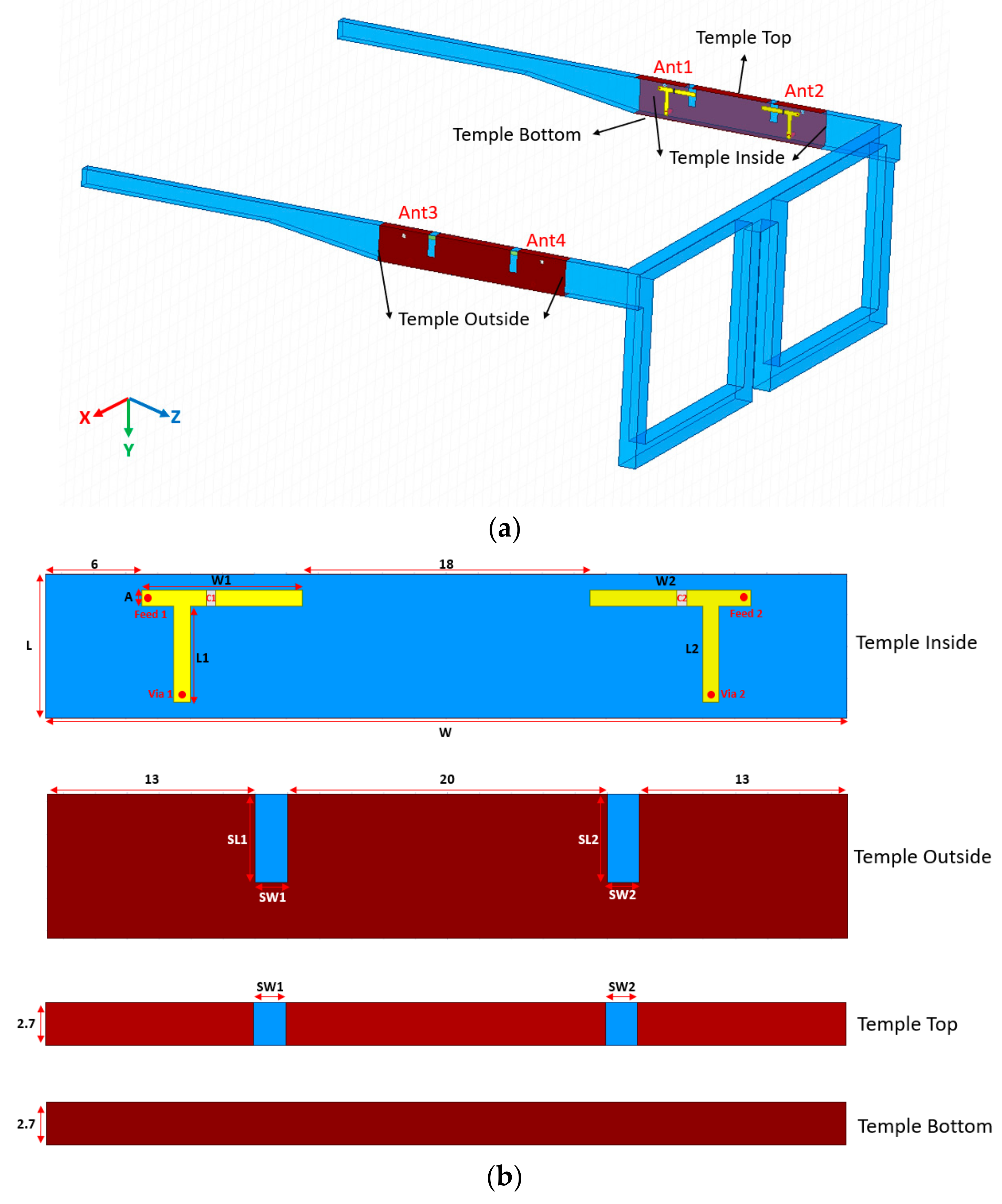
Figure 1 shows the 4 × 4 MIMO slot antenna system applied to the Wi-Fi 6e band proposed in this paper. The antenna system can be divided into an inverted-F antenna and a metal ground plane. The inverted-F antenna is manufactured by Laser Direct Structuring (LDS) on the inner side of the temple with a substrate made of polycarbonate (PC). The substrate thickness is 2.7 mm, the dielectric constant of polycarbonate is 2.85, and the dielectric loss tangent is 0.0092. The outside of the PC temples uses a sputtering coating process to ensure that the antenna’s metal ground and reserve slots have a coupling effect.

Figure 1.
(a) Geometry of the proposed 4 × 4 MIMO glasses antennas; (b) the dimensions of inverted-F antenna and slotted copper ground plane.
It can be seen from Figure 1a that the glasses proposed in this paper refer to the currently popular plastic glasses, and the overall size is 155 mm × 145 mm × 50 mm. The left temple is equipped with antenna 1 and antenna 2, and the right temple is equipped with antenna 3 and antenna 4. The left leg antenna and the right leg antenna have a symmetrical structure. Figure 1b is a detailed size figure of a single temple antenna. For the size code in the figure, please refer to Table 1. The slot antenna occupies an area of 50 mm × 9 mm × 2.7 mm on the temple. The slot extends from the outside of the temple top, the length of the SL is 5.5 mm, and the width of the SW is 2 mm. The inverted-F antenna feeds from the ground side at 6 mm, and there is a 1 pF capacitor in series in the middle of the antenna. The length L of the antenna is 6 mm, and it reaches the ground through the Via hole. Therefore, the four antennas installed on the plastic glasses are not obtrusive and can meet the requirements of the metal frame of the smart wearable device.

Table 1.
The dimensions of the proposed antenna.
2.1. Slot Antenna Simulation and Analysis
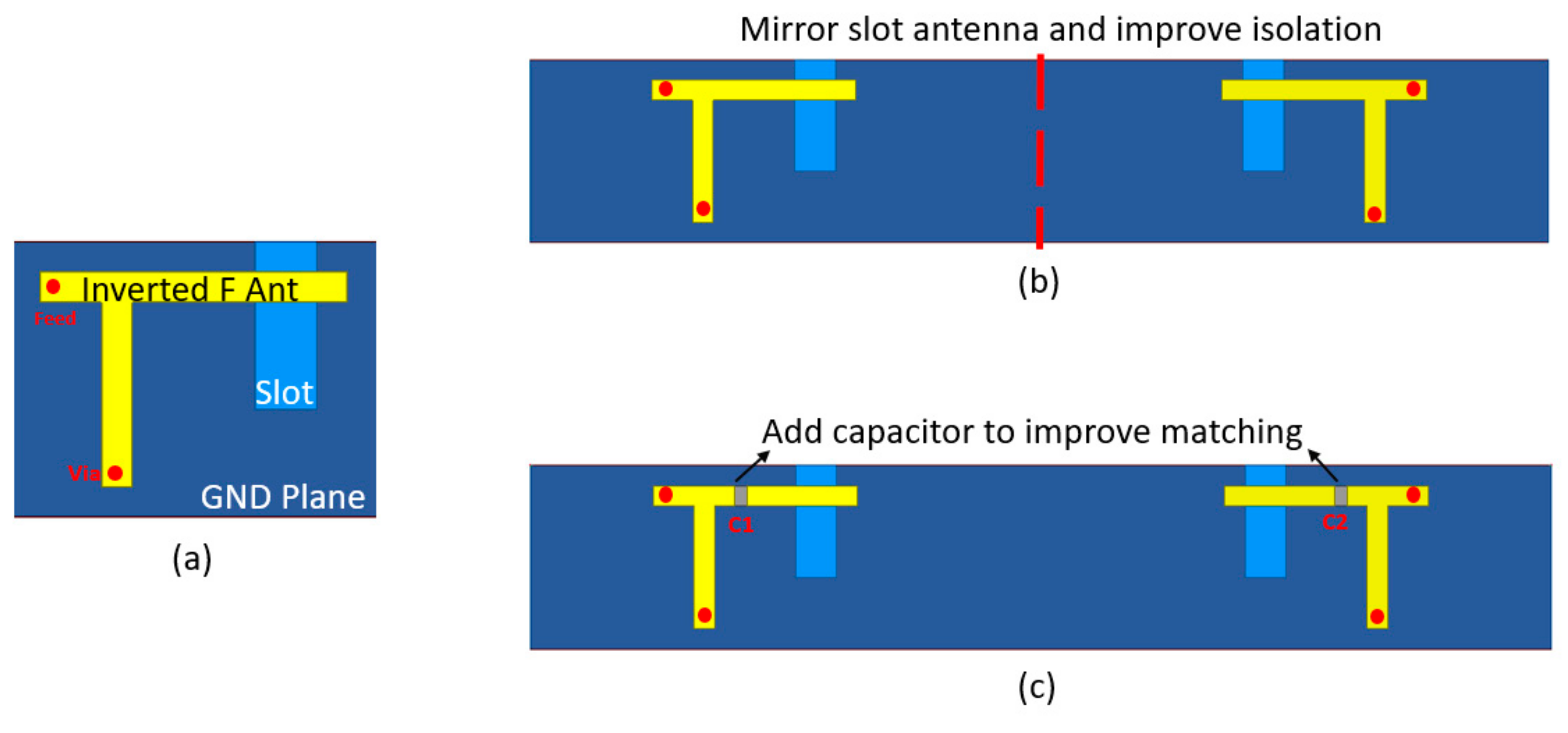
The antenna design steps proposed in this paper are shown in Figure 2. In Figure 2a, an inverted-F antenna that can be coupled to the slot is shown, which is grounded through a Via hole with a diameter of 1 mm. The ground plane is a metal copper layer covering the outer, top, and bottom sides of the glasses, and, according to the simulation results, slot holes are present on the outside grounding surface. Because the temple area is large, as Figure 2b shows, the eyewear device has another symmetrical antenna at a distance of 18 mm from the inverted-F antenna. Figure 2c shows two symmetrical inverted-F antennas with series capacitors, allowing the antenna to generate the resonance frequency of the target operating frequency band and, at the same time, enhance the isolation between the two antennas. Isolation performance is essential for MIMO antennas.

Figure 2.
The proposed slot antenna design steps. (a) Single slot antenna system; (b) Mirrored slot antenna system; (c) Series capacitor to improve impedance matching.
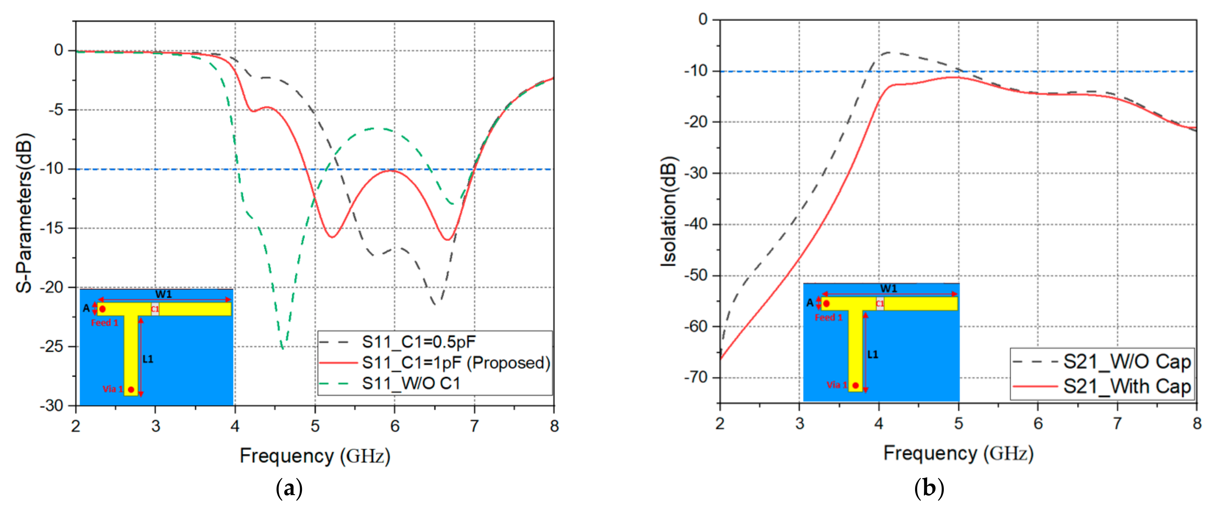
Next, the simulation software High-Frequency Structure Simulator (HFSS) version 2021R1 is used. First, we simulate and analyze the capacitance change, and then simulate and compare the length and width of the slot. The simulation results in Figure 3a show that when the antenna is as in Figure 2a, without series capacitors, the resonance frequency is generated by the entire slot antenna on 4.6 GHz and 6.7 GHz. However, the simulation results cannot cover the Wi-Fi 6e frequency band completely because the overall working frequency band cannot be continuous. Thus, we try to connect the inverted-F antenna in series with capacitive elements and adjust the capacitance value to change the resonance frequency of the slot antenna. When C1 = 0.5 pF, the working bandwidth cannot cover Wi-Fi 5G and Wi-Fi 6e. When C1 = 1 pF, the resonant points of the slot antenna can be obtained at 5.3 GHz and 6.6 GHz, and the working bandwidth can cover the entire Wi-Fi 5G and Wi-Fi 6e. Figure 3b presents a simulation of the presence or absence of a series capacitor. It is found that the series capacitor can improve the isolation between the two antennas, and the S21 is lower than −10 dB.
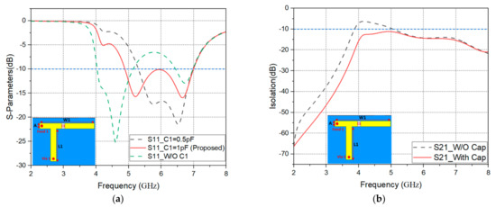
Figure 3.
S-parameter simulation results as: (a) capacitance change; (b) the effect of series capacitance on isolation.
In addition, we also simulate the change of slot size, and the result is shown in Figure 4a. When the slot length SL is 4.5 mm, from the reflection coefficient |S11|≤ −10 dB, it can be seen that the resonance frequency will move to the high-frequency direction at 5.3 GHz to 6.6 GHz, and the resonance intensity will be weakened. When the slot length SL is 6.5 mm, the resonance frequency of 6.6 GHz will move to the low-frequency direction, and the working bandwidth will also be reduced. Figure 4b shows that when the slot width SW is 1 mm, the resonance frequency will move to a low frequency at 5.3 GHz. When the slot width is 3 mm, the resonance frequency of 5.3 GHz will move to 6 GHz, and the overall operating frequency band will be weakened. In order to achieve the expected working frequency band and resonance strength, the proposed antenna SL is 5.5 mm, and the SW is 2 mm.
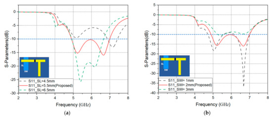
Figure 4.
S-parameter simulation results as: (a) slot length SL changes; (b) slot length SW changes.
2.2. Surface Current Distributions
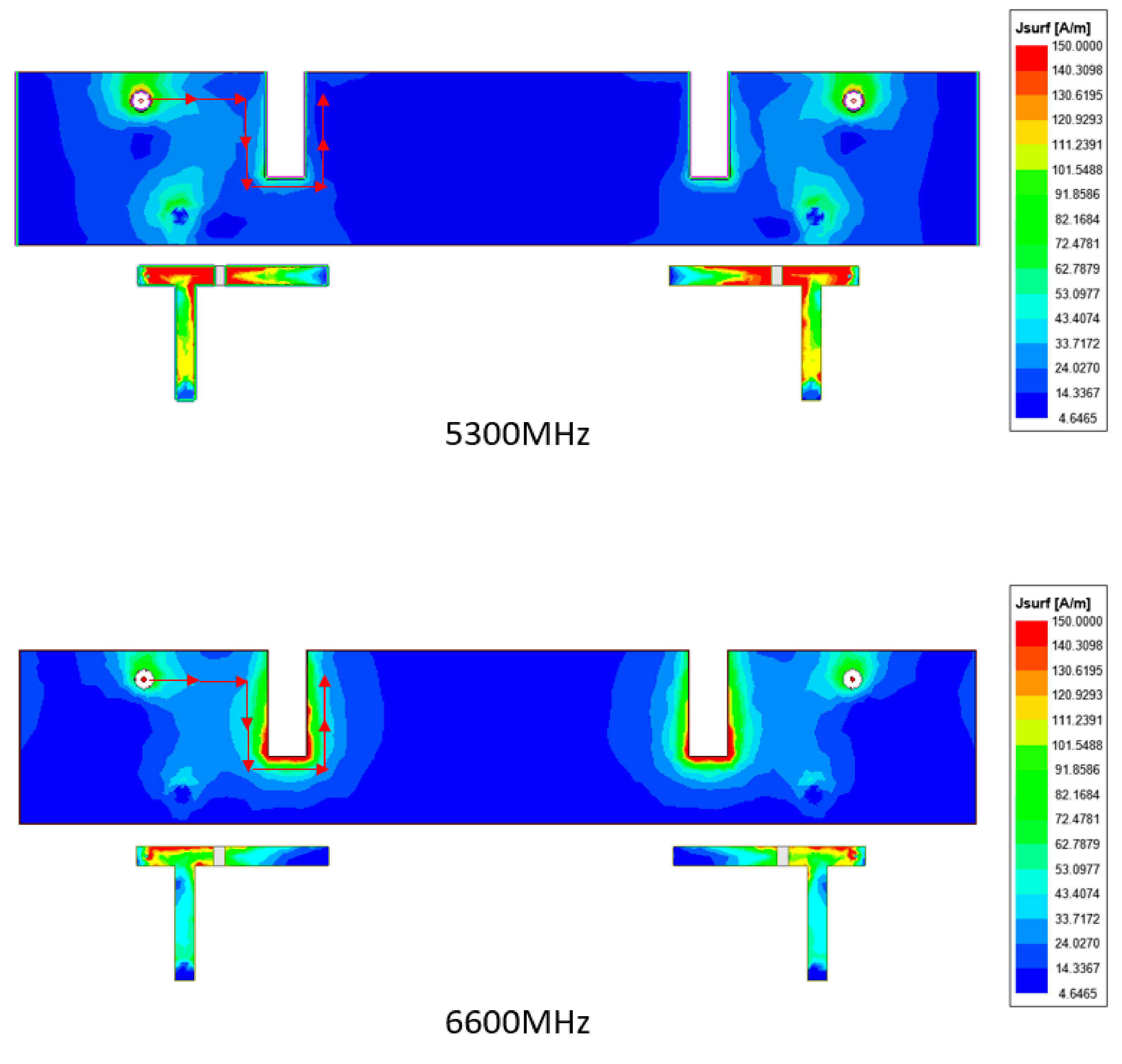
The operational mode of the slot antenna is based on the current entering from the feed point and exists in the entire inverted-F antenna. At the same time, this current will also be coupled around the slot and allow electromagnetic waves to radiate out of the slot. By adjusting the size of the slot, the target resonance frequency can be within the expected range. The surface current simulation results are shown in Figure 5. When the current enters from the feed point, the proposed antenna will exhibit current coupling on the slot at the expected working frequency band, and it can be found that the working resonance frequency is 5.3 GHz and 6.6 GHz, and the energy is concentrated around the slot on the outside of the temple. From the current energy distribution, it is known that there is almost no current energy distribution between the two antennas, so the symmetrical antenna can provide good isolation.

Figure 5.
Current distribution paths at 5.3 GHz and 6.6 GHz of Ant1 and Ant2.
3. SAR Simulation and Analysis
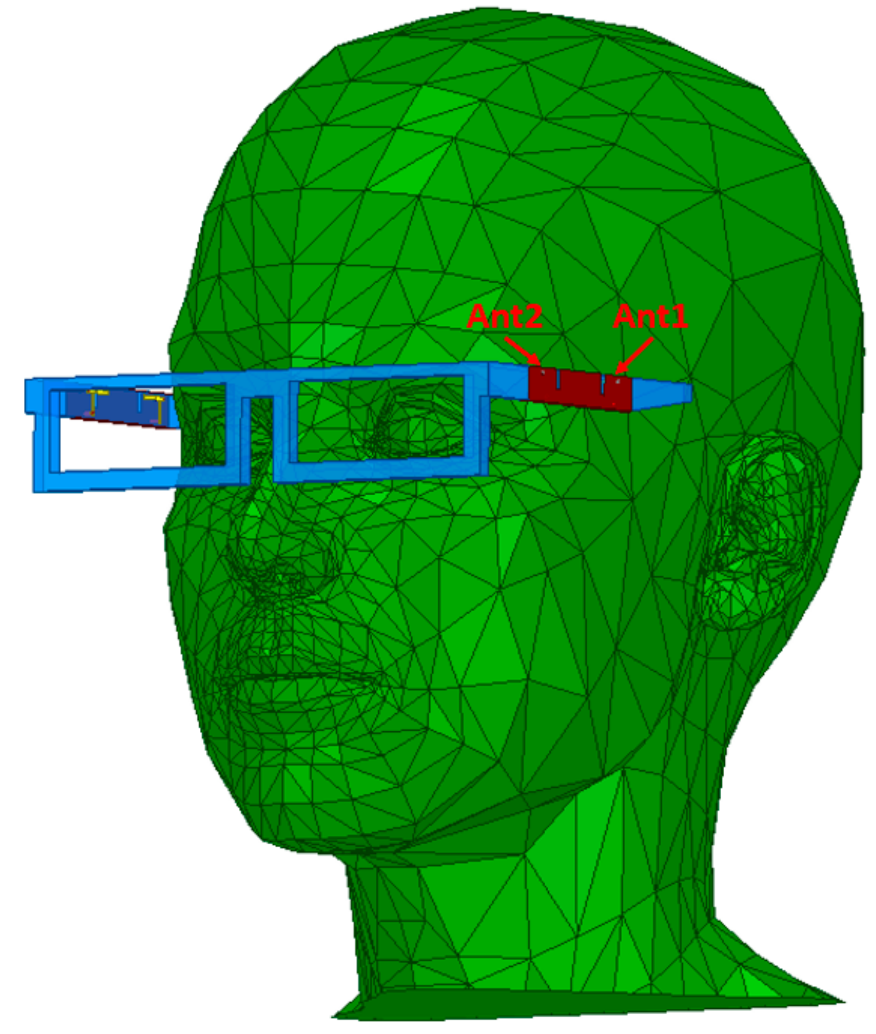
The human body is a high-loss material for the antenna. Therefore, the proposed antenna needs to be hung on the human head model for simulation, and we then observe whether the antenna’s performance is affected, so that the proposed antenna is more likely to be used in daily life. Figure 6 shows the use of HFSS to simulate the Wi-Fi 5G and Wi-Fi 6e eyewear antenna system, which is placed on a human head model.

Figure 6.
The proposed eyewear antenna on a head model.
Next, we discuss the changes in reflection coefficient and isolation when the proposed antenna is close to the head. It can be seen from Figure 6 that antenna 1 is closer to the head, and antenna 2 is farther from the head. Figure 7 shows the simulation by placing the glasses on the head. However, the proposed antenna is symmetrical, so only antenna 1 and antenna 2 are simulated. Figure 7a shows that when antenna 1 is at the head position, the working bandwidth is shortened due to the influence of the human body, and the reflection coefficient of antenna 2 is not significantly different between the head and the free space. Wireless products on the market can be accepted if the reflection coefficient is lower than −6 dB [24,25,26], and when the proposed antenna worn on the head that the S-parameter is lower than −6 dB. Therefore, it matches the CTIA specification standard. Figure 7b shows the isolation between antenna 1 and antenna 2, and the isolation is almost lower than −10 dB when hung on the head or in free space.
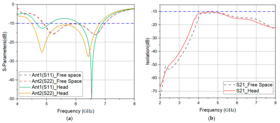
Figure 7.
Simulation in head and free space: (a) the S-parameters of Ant.1 and Ant.2; (b) the isolation between Ant.1 and Ant.2.
Smart wearable devices are the electronic products closest to the human body; these electronic products will transmit wireless communication through antennas, and electromagnetic radiation will definitely be generated during the transmission. Therefore, laws and regulations of various countries all have Specific Absorption Rate (SAR) specifications, which are mainly used to limit the electromagnetic radiation absorption caused by electronic products to the human body. For example, the FCC safety limit is 1 g SAR 1.6W/kg, and the European CE safety limit is 10 g SAR 2 W/kg. The SAR calculation method is the radiant power energy absorbed by a unit volume in a specific time, as shown in the following equation [22]:
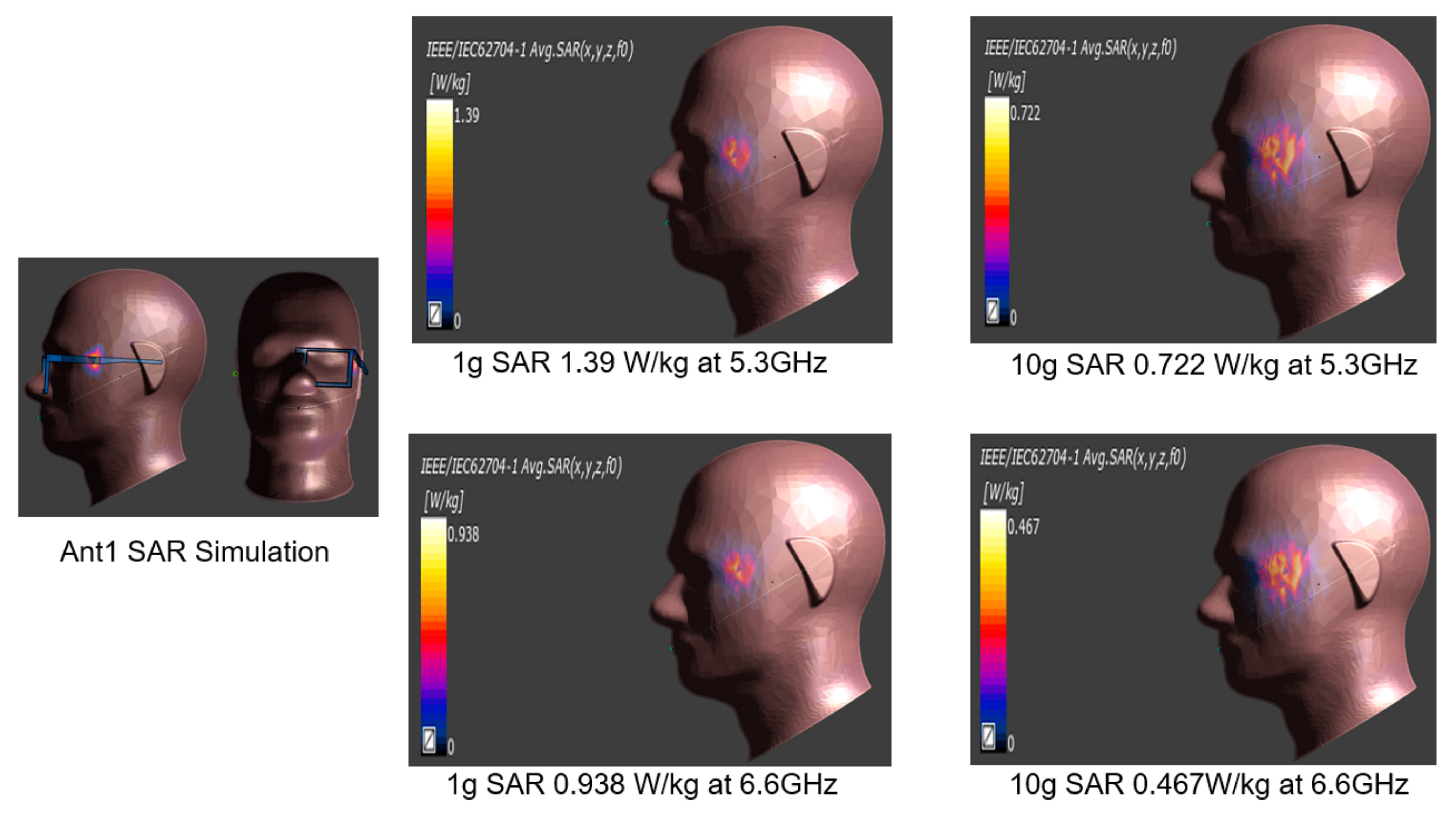
Antenna 1 and antenna 3 are closest to the human head in the proposed 4 × 4 MIMO slot antenna system, and the antenna structure is symmetrical, so only the SAR value of antenna 1 is simulated, and the SAR simulation software uses Sim4Life to operate. As shown in Figure 8, when antenna 1 is 10 mm away from the head, the input power from the feed point is 0.1 W (20 dBm), and the frequency at 5.3 GHz and 6.6 GHz to calculate the values of 1 g SAR and 10 g SAR. According to the simulation results, the 1 g SAR and 10 g SAR of antenna 1 at 5.3 GHz are 1.39 W/kg and 0.722 W/kg, respectively, and the 1 g SAR and 10 g SAR at 6.6 GHz are 0.938 W/kg and 0.467 W/kg, respectively. Thus, the above SAR values are all lower than the certification limit.
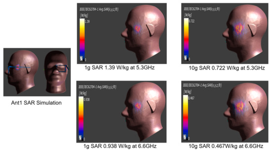
Figure 8.
Ant.1 SAR simulation results at 5.3 GHz and 6.6 GHz.
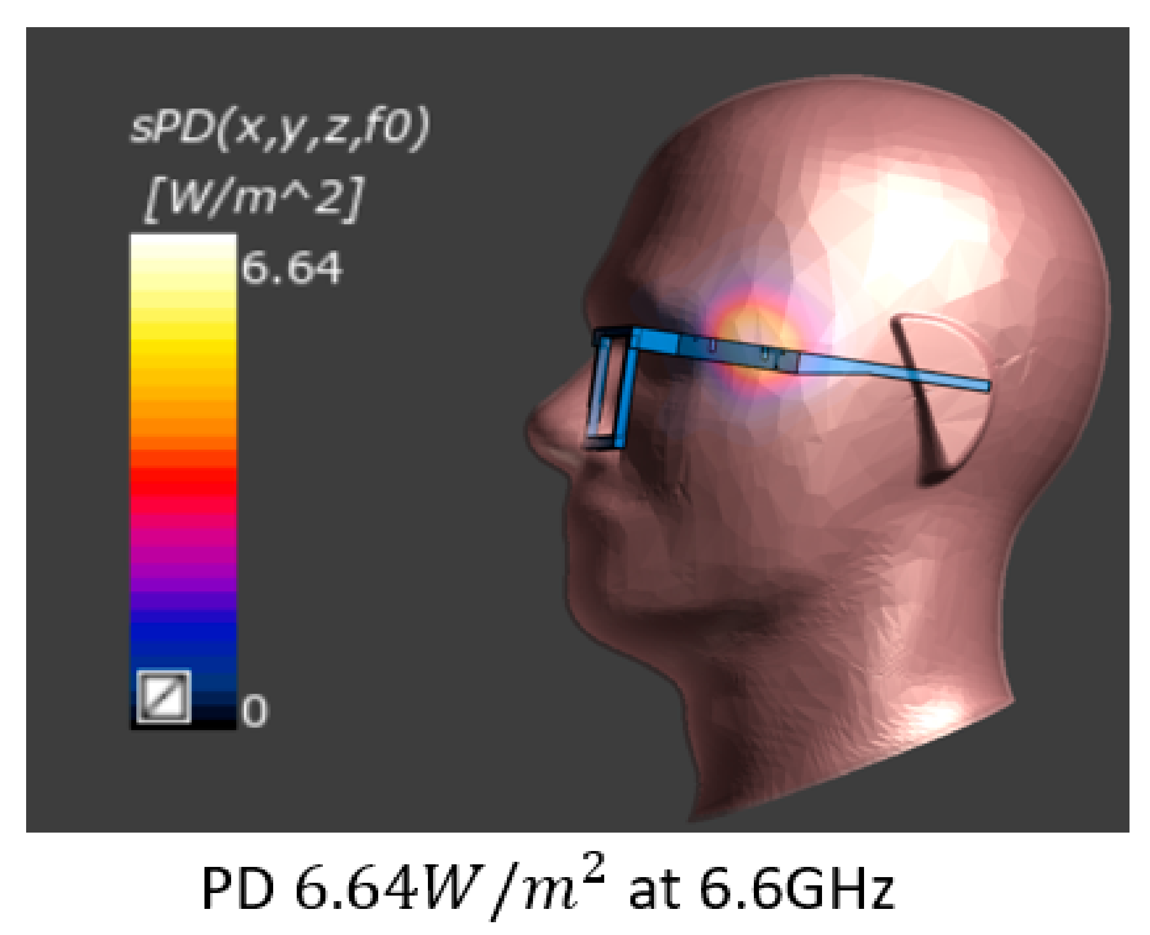
According to the FCC’s regulatory test requirements, when the wearable device supports the frequency band above 6 GHz, the power density (PD) needs to be measured. PD test frequency is selected which the frequency point has the worst SAR value, and PD safety limit value is . The equation is as follows [27]:
Figure 9 shows antenna 1 when the input power from the feed point is 0.1 W (20 dBm), and the frequency is 6.6 GHz to calculate the PD value. According to the simulation results, the PD of antenna 1 at 6.6 GHz is , which is lower than the limit of .
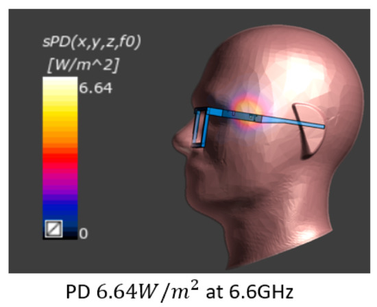
Figure 9.
Ant.1 SAR simulation results at 5.3 GHz and 6.6 GHz.
4. Experimental Characterization
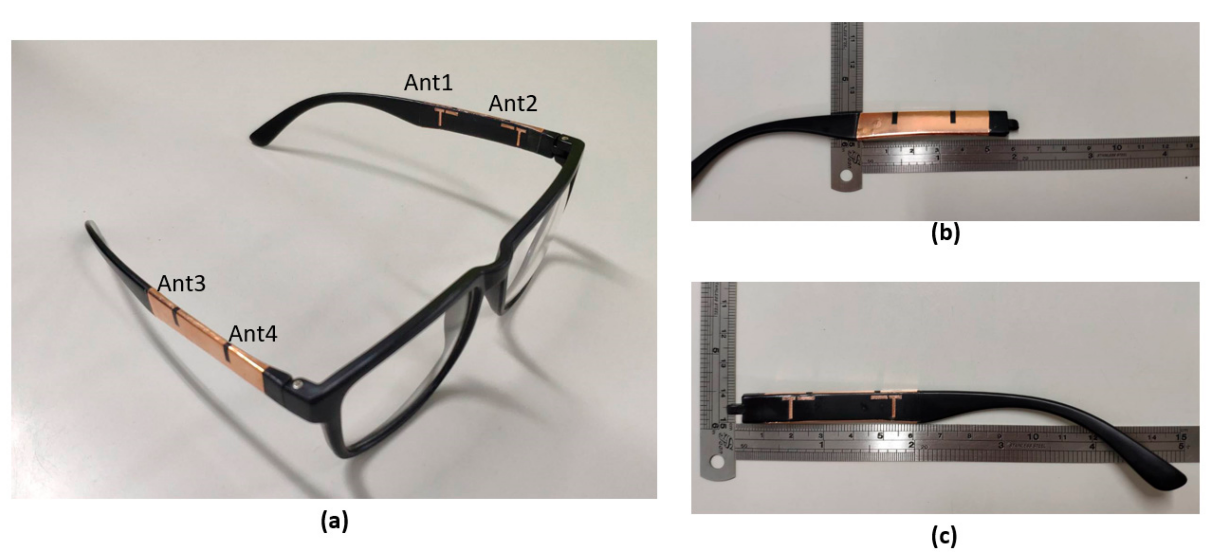
The actual work of the proposed 4 × 4 MIMO eyewear antenna has been completed, as shown in Figure 10. According to the above simulation results, the inverted-F antenna on the inside of the temples needs to reserve a block for soldering series capacitors. Unfortunately, the antenna substrate is made of PC (PC’s melting point is 220 °C), which cannot withstand general soldering operations. Therefore, we use low-temperature soldering to prevent abnormal antenna performance due to the deformation of the temples. Figure 10a shows a photo of the 4 × 4 MIMO plastic glasses. Figure 10b shows a ground plane of the sputtered copper layer with slots on the outside of the temple. Figure 10c shows an inverted-F antenna created by the LDS process on the inside of the temple.
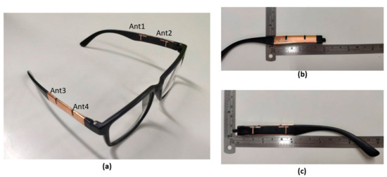
Figure 10.
Photographs of the proposed eyewear antennas. (a) 4 × 4 MIMO plastic glasses; (b) Outside of the temple; (c) Inside of the temple.
4.1. S-Parameter Analysis
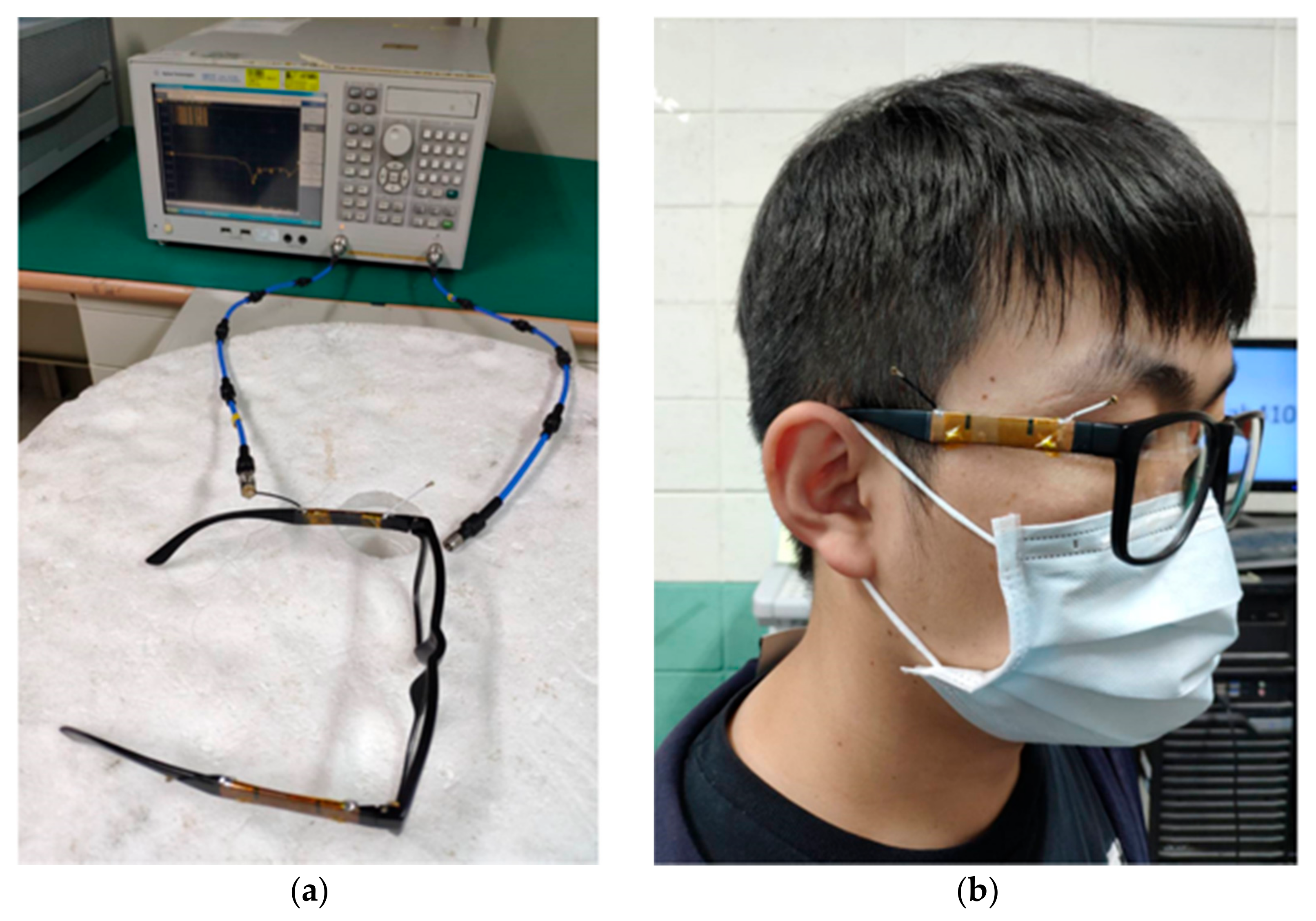
Because the proposed glasses’ antenna substrate is thick and the material is plastic with a low melting point, it is not suitable to use a copper pipe or SMA connector for measurement. Therefore, we use a coaxial cable with low-temperature soldering for measurement. The vector network analyzer model is Agilent E5071C, and we use the SOLT method to calibrate before the measurement, but deviation is present due to soldering and the inability to calibrate the coaxial cable. Therefore, the S-parameter measurement setup in free space is shown in Figure 11a, and the glasses are worn on the human head to measure the S-parameters, as shown in Figure 11b.

Figure 11.
Photographs of (a) the measurement setup for the S-parameter; (b) glasses on the human head to measure S-parameters.
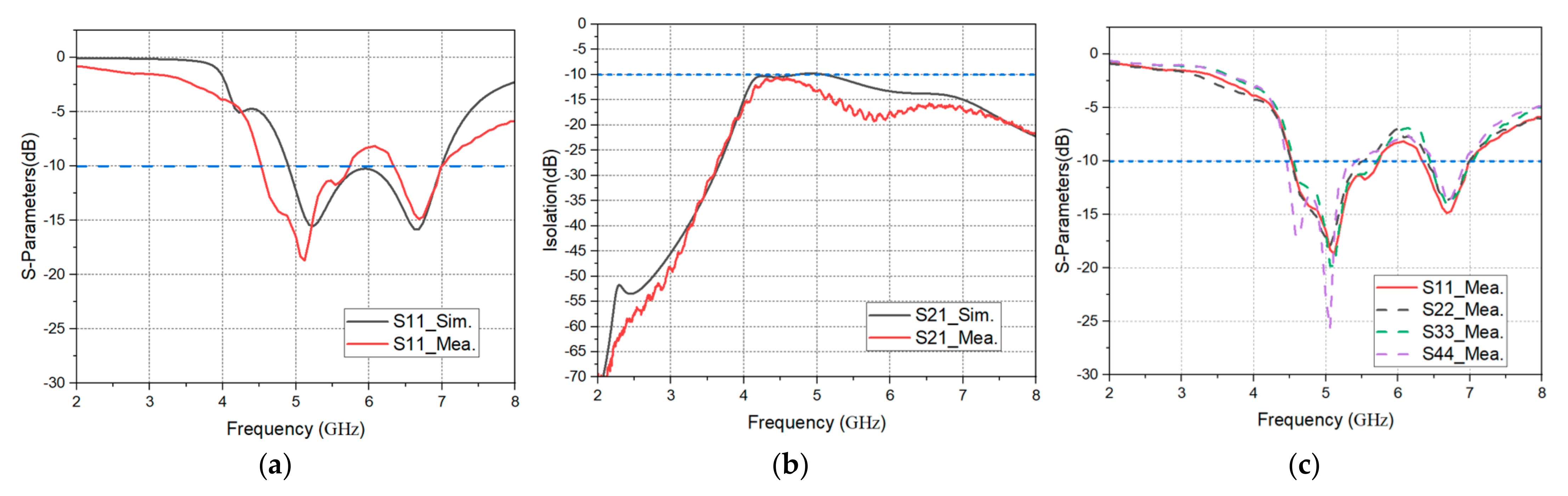
Figure 12a compares the S-parameter measurement and simulation of the single temple antenna 1. Due to the soldering and fabrication tolerances, frequency resonance may be weakened, but the measurement result is very similar to the simulation. Figure 12b compares the measurement and simulation of the isolation between antenna 1 and antenna 2. The isolation between the measurement and simulation can be lower than −10 dB, complying with the MIMO antenna system’s basic specifications. Figure 12c is the S-parameter measurement of four antennas. It is found that the effective working frequency bands of the four antennas are all in line with expectations. However, the reflection coefficient of antenna 4 is different from those of the other antennas. This deviation may be due to the soldering and fabrication tolerances.
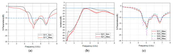
Figure 12.
Measured result for the proposed antenna: (a) Ant.1 reflection coefficient; (b) Ant.1 and Ant.2 isolation; (c) Ant.1~Ant.4 reflection coefficient.
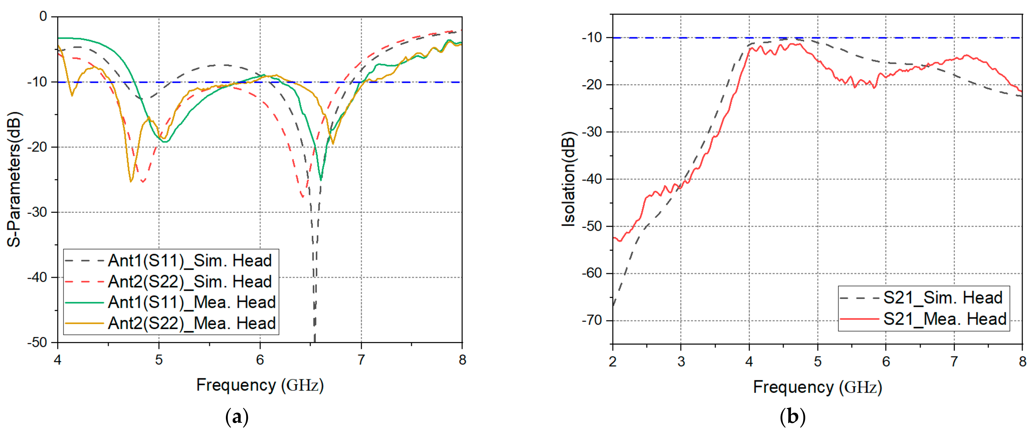
The proposed antenna is designed on the glasses device, so it is necessary to measure the glasses’ S-parameter on the human head. Because the proposed antenna is a symmetric antenna, we use the left-side temple with antenna 1 and antenna 2 to measure the S-parameter. Figure 13a shows the reflection coefficient measurement and simulation of antenna 1 and antenna 2. The simulation and measurement results are very similar. For antenna 2, simulation and measurement both move towards low frequencies. Figure 13b shows the isolation result of antenna 1 and antenna 2. Both the simulation and measurement yield values lower than −10 dB, and the trend is consistent.
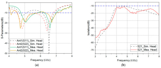
Figure 13.
Measurement results for glasses on the human head: (a) Ant.1 and Ant.2 reflection coefficient; (b) Ant.1 and Ant.2 isolation.
4.2. Radiation Pattern
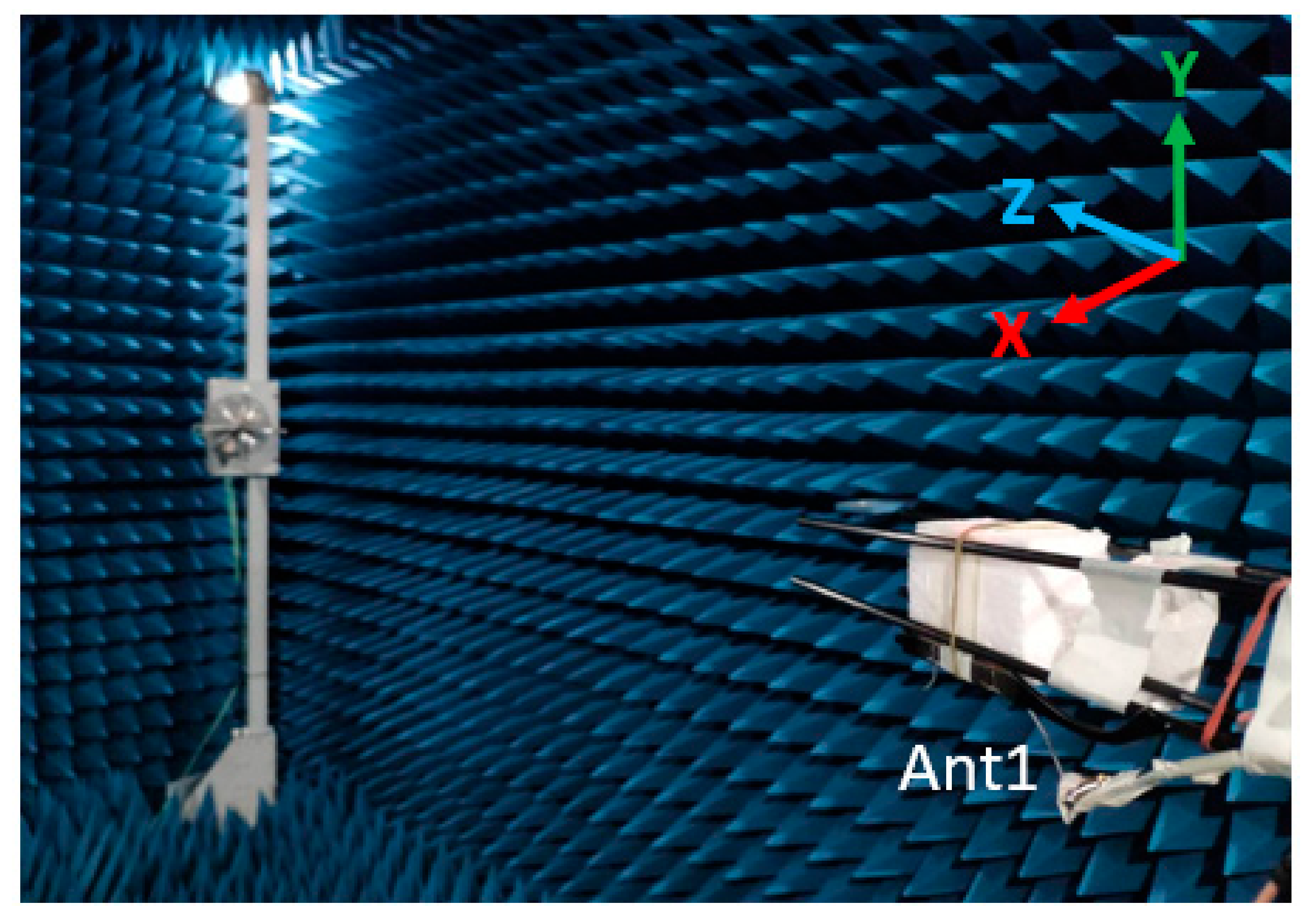
From the results in Figure 12c, it can be seen that the resonance modes of the four antennas are similar. Therefore, antenna 1 and antenna 2 are used for the following far-field test in this paper. The measurement field used this time is a standard far-field chamber, the network analyzer is the model Anritsu MS46524B, and the measurement frequency band of the horn antenna in the chamber is 0.1–8 GHz. Figure 14 shows a photo of the test environment of antenna 1 in the far-field chamber, and the XYZ axis of the simulation software corresponds to the XYZ axis of the chamber for elevation.
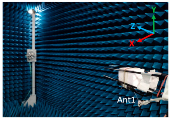
Figure 14.
Photograph of Ant.1 erected in a far-field chamber.
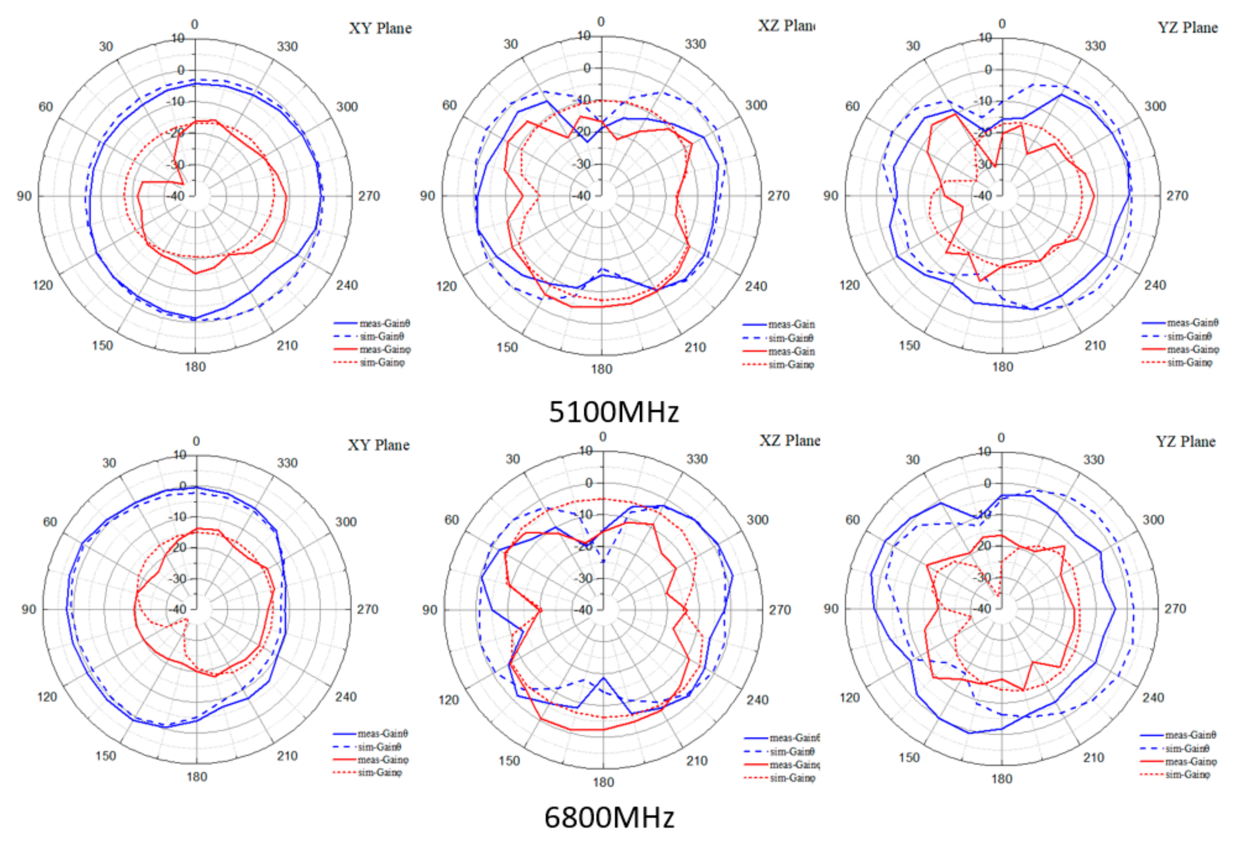
The proposed glasses’ antenna works in linear polarization. In a specific receiving range, it will have better signal reception than a circularly polarized antenna. Currently, linearly polarized antennas are widely used in wireless communication products. Figure 15 and Figure 16 show the 2D gain field patterns of the simulated and measured eyewear antenna in the XY plane, the XZ plane, and the YZ plane. From Figure 15 and Figure 16, it can be seen that the simulated and measured radiation modes have the same trend when antenna 1 and antenna 2 are at the working frequency of 5.1 GHz and 6.8 GHz.
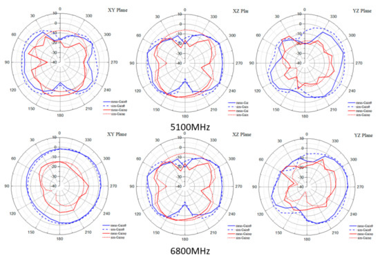
Figure 15.
Measured 2D radiation patterns of the proposed eyewear Ant.1.
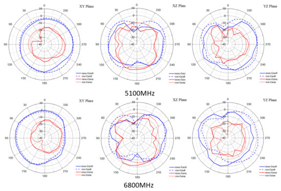
Figure 16.
Measured 2D radiation patterns of the proposed eyewear Ant.2.
4.3. Antenna Gain, Efficiency, and ECC
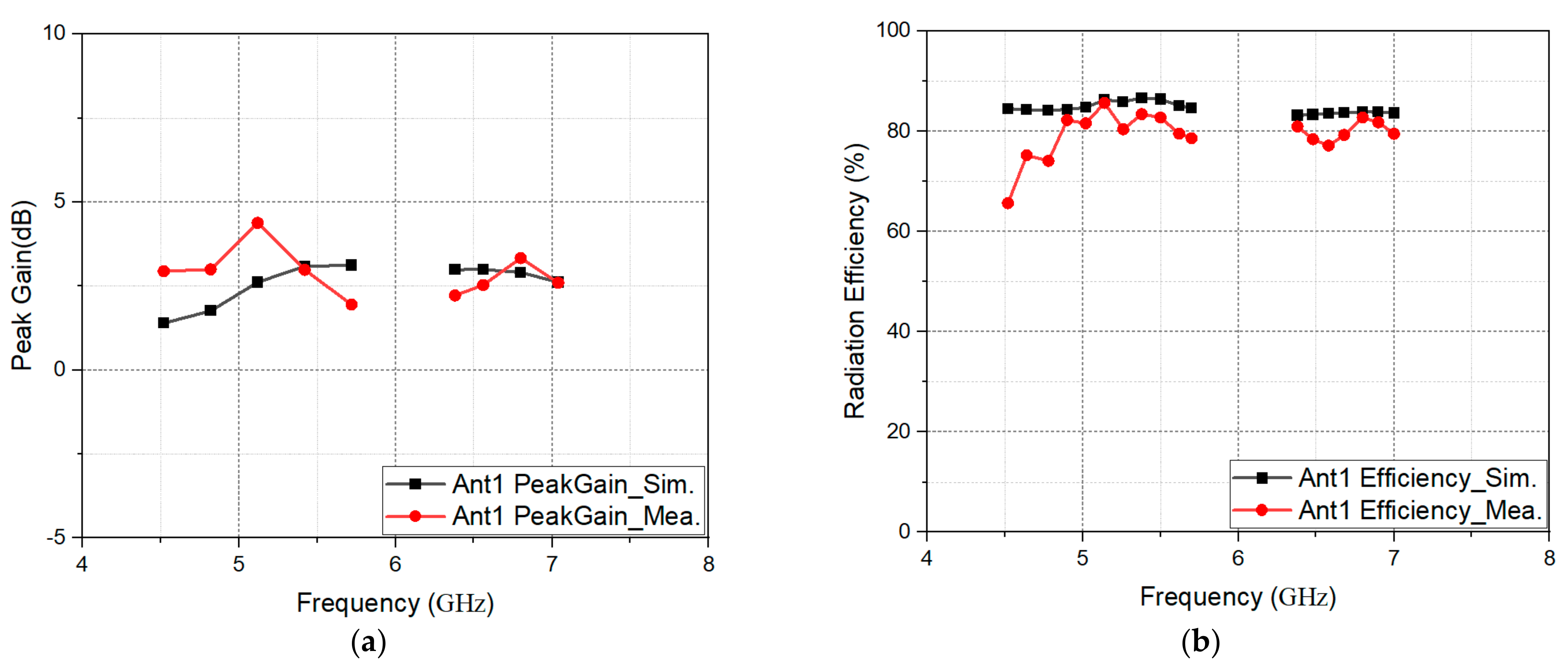
The gain and efficiency of antenna 1 can be seen in Figure 17a,b. The working frequency of antenna 1 can reach 4.3 dBi peak gain and 85.69% antenna efficiency in free space at 5.14 GHz and reach 3.3 dBi and 82.78% antenna efficiency in free space at 6.8 GHz.

Figure 17.
Measured result for the proposed eyewear Ant.1: (a) peak gain, (b) radiation efficiency.
When the antenna belongs to the MIMO system, the Envelope Correlation Coefficient (ECC) value is usually used to judge whether the antenna’s independence is good. The coupling effect between two antennas is poor when the ECC value is lower, and less of the transmission rate will be affected. The internationally recognized ECC limit value is 0.5. The ECC values of the two antennas can be calculated using the S-parameter equation as follows [16]:
Another ECC calculation method is to use the antenna radiation direction calculation. The ECC value equation of the two antennas is as follows [17]:
In the MIMO antenna system, when port 1 is excited and other ports are connected to a 50-ohm load, the far-field radiation direction generated by antenna 1 can be represented by . When port 2 is excited, the far-field radiation direction generated by antenna 2 can be represented by .
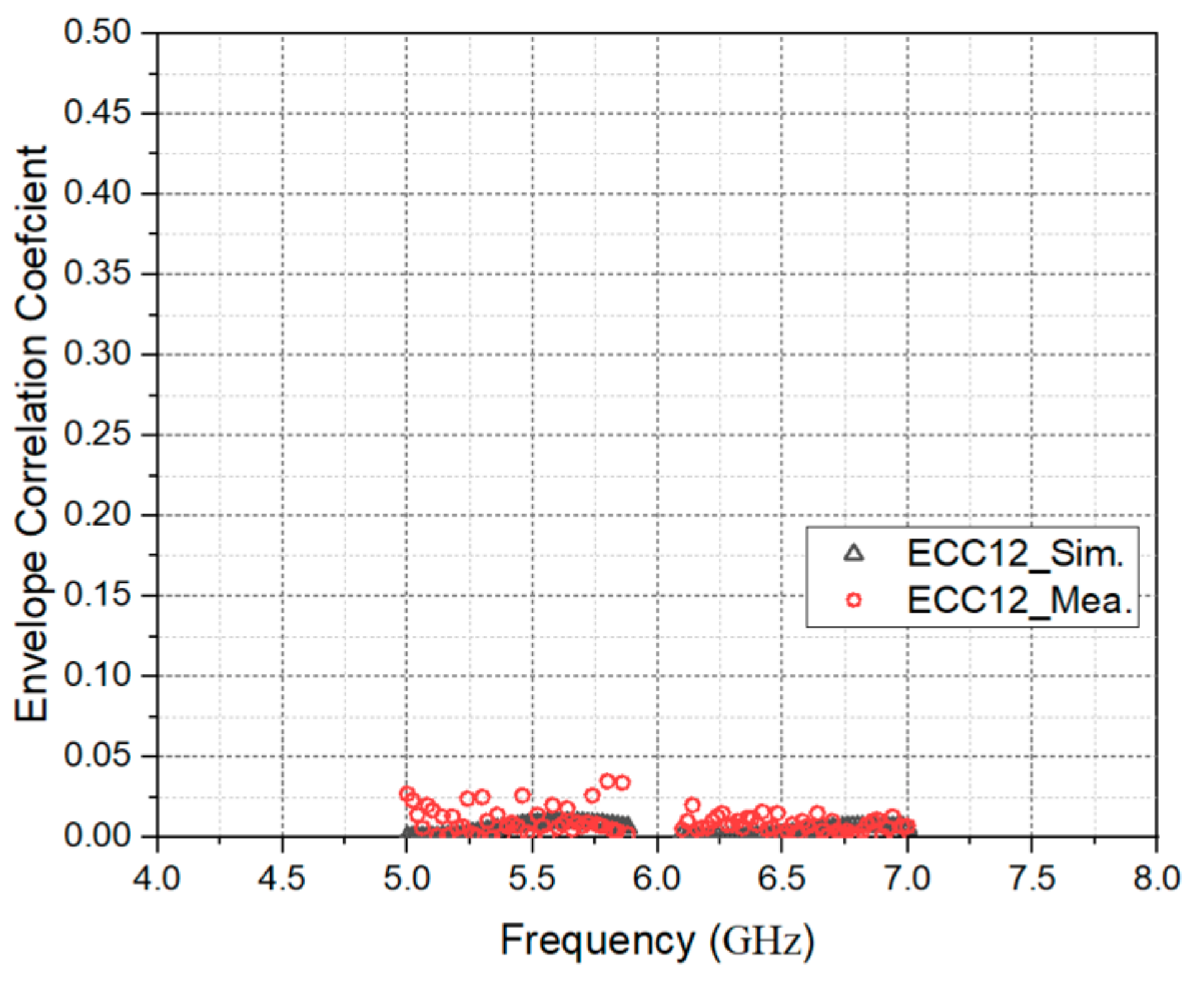
Figure 18 shows the ECC measurement and simulation comparison of antenna 1 and antenna 2 on a single temple. Again, it can be seen that in the effective working frequency band, the measured and simulated ECC values do not exceed 0.05, and the antenna’s independence is good.
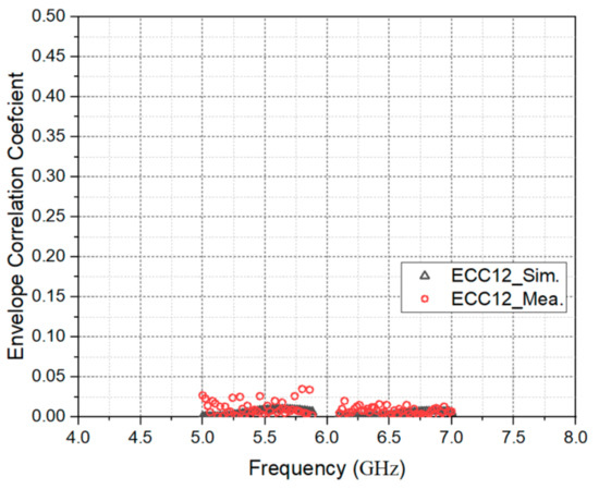
Figure 18.
Measured and simulated ECC for Ant.1 and Ant.2.
Table 2 offers a comparison between the proposed antenna and other eyewear antennas. It can be seen that the reference antennas [1,3,14] only support Wi-Fi 2.4 G, and the antenna efficiency is not good. For example, in [3], the antenna efficiency is only 10.7%. The application of 60GHz eyewear antenna is mentioned in references [4] and [28]. Although references [4] and [28] have high antenna gain, but the complex design of the array antenna makes it difficult to realize the MIMO system on the glasses. After comparing the references of LTE frequency bands that references [20] and [29] support multiple LTE frequency bands, but the antenna gain is not good [20] and the operating frequency is not continuous [29]. Reference [30] used an eyewear frame antenna and supported IoT 5.8 G, but it did not possess a MIMO function. In summary, no antenna design supports Wi-Fi 6e in the current references. However, our proposed eyewear antenna has a wide working bandwidth, high antenna efficiency, high antenna gain, supports 4 × 4 MIMO, and can be applied to the Wi-Fi 5G and Wi-Fi 6e bands.
Table 2.
Comparison between proposed work and references.
5. Conclusions
This paper proposes a method that allows standard plastic glasses in daily life to undergo a unique antenna manufacturing process, which can also be applied to Wi-Fi 5G and Wi-Fi 6e communication bands. Mainly relying on the antenna LDS process, four symmetrical slot antennas are carved on the plastic temples so that the plastic glasses can also achieve the 4 × 4 MIMO transmission effect. Furthermore, such an antenna configuration can make full use of the glasses’ space to receive the signal on the left and right without blind spots. At the end of this study, a physical antenna was successfully produced, and the actual measurement results show that the efficiency and gain of the antenna are good, meaning that the smart plastic glasses have a high probability of being used in Wi-Fi 5G and Wi-Fi 6e application scenarios in the future.
Author Contributions
Conceptualization, M.-A.C.; methodology, M.-A.C.; software, M.-A.C., C.-W.H., C.-W.Y., and B.-R.C.; validation, C.-W.H. and C.-W.Y.; formal analysis, M.-A.C., C.-W.H., and C.-W.Y.; investigation, M.-A.C.; resources, M.-A.C.; writing—original draft preparation, M.-A.C. and C.-W.H.; writing—review and editing, M.-A.C.; visualization, M.-A.C.; supervision, M.-A.C.; project administration, M.-A.C.; funding acquisition, M.-A.C. All authors have read and agreed to the published version of the manuscript.
Funding
This work was supported by the Ministry of Science and Technology, Taiwan, under Grant Project MOST 109-2222-E-027-008.
Data Availability Statement
All data are included within the manuscript.
Conflicts of Interest
The authors declare no conflict of interest.
References
- Hong, S.; Kang, S.H.; Kim, Y.; Jung, C.W. Transparent and Flexible Antenna for Wearable Glasses Applications. IEEE Trans. Antennas Propag. 2016, 64, 2797–2804. [Google Scholar] [CrossRef]
- Faith, K.; Atef, Z.E. Smart Glasses Radiation Effects on a Human Head Model at Wi-Fi and 5G Cellular Frequencies. In Proceedings of the International ACES Communications, Beijing, China, 29 July–1 August 2018. [Google Scholar]
- Cihangir, A.; Gianesello, F.; Luxey, C. Dual Antenna Concept with Complementary Radiation for Eyewear Applications. IEEE Trans. Antennas Propag. 2018, 66, 3056–3063. [Google Scholar] [CrossRef]
- Bisognin, A.; Cihangir, A.; Luxey, C.; Jacquemod, G.; Pilard, R.; Gianesello, F.; Costa, J.R.; Fernandes, C.A.; Lima, E.B.; Panagamuwa, C.J.; et al. Ball Grid Array-Module with Integrated Shaped Lens for WiGig Applications in Eyewear Devices. IEEE Trans. Antennas Propag. 2017, 65, 6380–6394. [Google Scholar] [CrossRef]
- Cihangir, A.; Panagamuwa, C.J.; Whittow, W.G.; Gianesello, F.; Luxey, C. Ultrabroadband Antenna with Robustness to Body Detuning for 4G Eyewear Devices. IEEE Trans. Antennas Propag. 2017, 16, 1225–1228. [Google Scholar] [CrossRef]
- Nakano, H.; Yamauchi, J. Printed Slot and Wire Antennas: A Review. Proc. IEEE 2012, 100, 2158–2168. [Google Scholar] [CrossRef]
- Chen, S.C.; Hsu, M.C. LTE MIMO Closed Slot Antenna System for Laptops with a Metal Cover. IEEE Access 2019, 7, 28973–28981. [Google Scholar] [CrossRef]
- Barani, I.R.R.; Wong, K. Integrated Inverted-F and Open-Slot Antennas in the Metal-Framed Smartphone for 2 × 2 LTE LB and 4 × 4 LTE M/HB MIMO Operations. IEEE Trans. Antennas Propag. 2018, 66, 5004–5012. [Google Scholar] [CrossRef]
- Cai, Q.; Li, Y.; Zhang, X.; Shen, W. Wideband MIMO Antenna Array Covering 3.3—7.1 GHz for 5G Metal-Rimmed Smartphone Applications. IEEE Access 2019, 7, 142070–142084. [Google Scholar] [CrossRef]
- Liao, C.T.; Yang, Z.K.; Chen, H.M. Multiple Integrated Antennas for Wearable Fifth-Generation Communication and Internet of Things Applications. IEEE Access 2021, 9, 120328–120346. [Google Scholar] [CrossRef]
- Yao, L.; Li, E.; Yan, J.; Shan, Z.; Ruan, X.; Shen, Z.; Ren, Y.; Yang, J. Miniaturization and Electromagnetic Reliability of Wearable Textile Antennas. Electronics 2021, 10, 994. [Google Scholar] [CrossRef]
- Li, K.; Dong, T.; Xia, Z. Wideband Printed Wide-Slot Antenna with Fork-Shaped Stub. Electronics 2019, 8, 347. [Google Scholar] [CrossRef] [Green Version]
- Zhang, S.; Zhao, K.; Ying, Z.; He, S. Adaptive Quad-Element Multi-Wideband Antenna Array for User-Effective LTE MIMO Mobile Terminals. IEEE Trans. Antennas Propag. 2013, 61, 4275–4283. [Google Scholar] [CrossRef]
- Choi, S.; Choi, J. Miniaturized MIMO Antenna with a High Isolation for Smart Glasses. In Proceedings of the IEEE-APS Topical Conference on Antennas and Propagation in Wireless Communications, Verona, Italy, 11–15 September 2017. [Google Scholar]
- Tang, Z.; Wu, X.; Zhan, J.; Hu, S.; Xi, Z.; Liu, Y. Compact UWB-MIMO Antenna with High Isolation and Triple Band-Notched Characteristics. IEEE Access 2019, 7, 19856–19865. [Google Scholar] [CrossRef]
- Kulkarni, J.; Desai, A.; Desmond, C.Y. Wideband Four-Port MIMO Antenna Array with High Isolation for Future Wireless Systems. Int. J. Electron. Commun. 2021, 128, 1–15. [Google Scholar] [CrossRef]
- Haq, M.A.U.; Koziel, S. Ground Plane Alterations for Design of High-Isolation Compact Wideband MIMO Antenna. IEEE Access 2018, 6, 48978–48983. [Google Scholar] [CrossRef]
- Khalid, H.; Awan, W.A.; Hussain, M.; Fatima, A.; Ali, M.; Hussain, N.; Khan, S.; Alibakhshikenari, M.; Limiti, E. Design of an Integrated Sub-6 GHz and mmWave MIMO Antenna for 5G Handheld Devices. Appl. Sci. 2021, 11, 8331. [Google Scholar] [CrossRef]
- Le, T.T.; Yun, T.Y. Wearable Dual-Band High-Gain Low-SAR Antenna for Off-Body Communication. IEEE Antennas Wirel. Propag. Lett. 2021, 20, 1175–1179. [Google Scholar] [CrossRef]
- Cihangir, A.; Panagamuwa, C.J.; Whittow, W.G.; Jacquemod, G.; Gianesello, F.; Pilard, R.; Luxey, C. Dual-band 4G eyewear antenna and sar implications. IEEE Trans. Antennas Propag. 2017, 65, 2085–2089. [Google Scholar] [CrossRef] [Green Version]
- RF Exposure Procedures and Equipment Authorization Policies for Mobile and Portable Devices. Available online: https://apps.fcc.gov/oetcf/kdb/forms/FTSSearchResultPage.cfm?switch=P&id=20676 (accessed on 23 October 2015).
- IEEE Recommended Practice for Determining the Peak Spatial-Average Specific Absorption Rate (SAR) in the Human Head from Wireless Communications Devices: Measurement Techniques. Available online: https://ieeexplore.ieee.org/document/6589093 (accessed on 6 September 2013).
- FCC Wi-Fi 6E RF Exposure—FCC Report. Available online: https://fcc.report/FCC-ID/MSQI005D/5126834.pdf (accessed on 4 February 2021).
- Chung, M.A.; Chang, W.H. Low-cost, low-profile and miniaturized single-plane antenna design for an Internet of Thing device applications operating in 5G, 4G, V2X, DSRC, WiFi 6 band, WLAN, and WiMAX communication systems. Microw. Opt. Technol. Lett. 2020, 62, 1765–1773. [Google Scholar] [CrossRef]
- Abdullah, M.; Kiani, S.H.; Abdulrazak, L.F.; Iqbal, A.; Bashir, M.A.; Khan, S.; Kim, S. High-Performance Multiple-Input Multiple-Output Antenna System for 5G Mobile Terminals. Electronics 2019, 8, 1090. [Google Scholar] [CrossRef] [Green Version]
- Yang, P. Reconfigurable 3-D Slot Antenna Design for 4G and Sub-6G Smartphones with Metallic Casing. Electronics 2020, 9, 216. [Google Scholar] [CrossRef] [Green Version]
- He, W.; Xu, B.; Yao, Y.; Colombi, D.; Ying, Z.; He, S. Implications of Incident Power Density Limits on Power and EIRP Levels of 5G Millimeter-Wave User Equipment. IEEE Access 2020, 8, 148214–148225. [Google Scholar] [CrossRef]
- Hong, Y.; Chou, J. 60 GHz Patch Antenna Array with Parasitic Elements for Smart Glasses. IEEE Antennas Wirel. Propag. Lett. 2018, 17, 1252–1256. [Google Scholar] [CrossRef]
- Wang, Y.Y.; Ban, Y.L.; Liu, Y. Sub-6GHz 4G/5G Conformal Glasses Antennas. IEEE Access 2019, 7, 182027–182036. [Google Scholar] [CrossRef]
- Wang, Y.; Zhang, J.; Peng, F.; Wu, S. A Glasses Frame Antenna for the Applications in Internet of Things. IEEE Internet Things J. 2019, 6, 8911–8918. [Google Scholar] [CrossRef]


Publisher’s Note: MDPI stays neutral with regard to jurisdictional claims in published maps and institutional affiliations. |
© 2021 by the authors. Licensee MDPI, Basel, Switzerland. This article is an open access article distributed under the terms and conditions of the Creative Commons Attribution (CC BY) license (https://creativecommons.org/licenses/by/4.0/).