Abstract
A post-wall-structured tapered slot antenna (PWTSA) loaded with an embedded metamaterial-based lens (metalens) is proposed and investigated for short-pulse applications. The proposed embedded metalens consists of not only a metallic delay lens, but also an airy acceleration region surrounding the lens, which is different from the conventional metalenses used in various tapered slot antennas and can exhibit a small equivalent permittivity. Therefore, the embedded metalens has a large usable range of permittivity and does not increase the size of the original prototype PWTSA. The post-wall structure and metalens of the proposed antenna can help it achieve a comprehensive and balanced performance, including a high fidelity, low cross-polarization, stable main-lobe direction and gain enhancement. The simulated and measured results show that without any increase in antenna size, the proposed antenna enhances the realized gain by 6.4 dB over the frequency range from 9 to 26 GHz and achieves a stable radiation with the offset of the main-lobe direction being confined to 2° up to 24.9 GHz. Furthermore, the cross-polarization levels are less than −20 dB and the fidelity is kept high for the short-pulse radiation with the frequency spectrum up to 30 GHz.
1. Introduction
Tapered slot antenna (TSA) is an end-fire travelling wave antenna with a low profile, wide impedance bandwidth, moderate gain, symmetrical radiation patterns, and good time-domain characteristics [1,2]. Therefore, it is widely used in short-pulse systems, broadband phased array antenna systems, and ultra-wideband communication systems [3,4,5,6,7,8,9]. However, in the upper region of the frequency band, the phase distribution of the electromagnetic (EM) field at the radiation aperture is not uniform due to the large physical aperture of a conventional TSA. The uneven phase distribution results in the splitting and shifting of the main radiation lobe and thus limits the actual gain bandwidth, radiation stability, and short-pulse radiation capability [10,11,12].
Diverse approaches have been developed to improve the radiation directivity and increase the gain of the TSA. One method is to load dielectric directors or a lens in front of the antenna aperture in the end-fire direction, such as extending the antenna substrate with various shapes or placing a gradient refractive index lens [13,14,15,16,17,18,19,20,21]. This method can be used to improve the antenna gain by about 1–9.5 dB, especially at the higher frequencies, with an enlarged configuration. Another approach widely utilized is to etch slits or slots on the edges of the radiation patch to enhance the antenna gain by changing the surface currents distribution, which achieves different gain improvement levels depending on different slit design and is more effective at the lower frequencies [22,23,24,25]. For example, in [18], dual-scale slotted edges were applied to reduce diffraction interference to enhance gain by a maximum of 3 dB at lower frequencies.
With the rapid development of metamaterials in the past decades, one effective approach that has been widely studied is to load anisotropic metasurfaces (MSs) or anisotropic zero-index metamaterials (ZIM) in the radiation aperture region of the TSA to form a flat focusing lens without additional increase in the antenna size [26,27,28,29]. However, the resonant characteristic of the MSs/ZIM unit cells that is used to realize the gain enhancement makes it difficult to apply effectively over an ultra-wide bandwidth. Besides, the gain enhancement levels of this approach are usually around 1–4 dB. As reported in [26], the anisotropic ZIM designed using meander-line resonator unit cells was embedded into the Vivaldi antenna and realized a maximum gain enhancement of about 4 dB in the frequency band of 9.5–10.5 GHz. In [28], a planar antipodal Vivaldi antenna array loaded with anisotropic MSs was designed and the gain of the antenna array was improved from 8.5–11.2 dBi to 9.35–12 dBi in the frequency band of 24.75–28.35 GHz compared to the unloaded antenna array.
Another gain improvement technique for TSA is to use loading metallic structures, such as surface plasmon polaritons, metal patches or strips, and non-resonant artificial material, in the end-fire direction of the antenna to improve the radiation directivity in a quite broad band [30,31,32,33,34,35,36,37,38]. Typically, reference [30] reported a gain enhancement of 2 dB in the band of 22–27.5 GHz for an antipodal TSA loaded with spoof surface plasmon polaritons extending from the radiation aperture to the region beyond the antenna arms, and thus the proposed antenna was quite large in length. In [31], an elliptical pseudo element patch and irregularly spaced notches were added to the TSA and realized high gains ranging from 4 dBi to a maximum of 16 dBi over a wideband of 2.5–57 GHz, with an antenna length of 186 mm. In [32,33,34], metal patches or strips array were added in the radiation direction as directors to improve the radiation of the TSA. Among them, the largest gain increase realized by optimized strips array reported in [34] was with a maximum gain increase of 3 dB from 4 to 6 GHz. In [35,36,37]; non-resonant artificial materials were utilized to improve the radiation of the TSA in wide bandwidths. The loading artificial materials were placed in front of the TSA arms with an extended antenna length. Moreover, although the above-referred designs have enhanced gain in a wide frequency band, all miss the effect of the improvement on the fidelity of ultra-wideband short-pulse applications, one of the important performance indicators for TSA. In [38], the improvement of radiation gain for antipodal TSA in short-pulse ground penetrating radar systems was studied by loading non-resonant artificial material in the radiation aperture, with the stable radiation ranging from 2 to 7 GHz and a peak gain increase of 1.7 dB.
The ZIM can achieve a very small equivalent dielectric permittivity, but their bandwidth is narrow. Moreover, the aforementioned works focus mainly on gain/direction enhancement or a few parameters and pay little attention to the performance in the time domain, which is important to short-pulse applications of those wideband TSAs. For diverse applications, it is desired to devise a loaded TSA with a comprehensive and balanced performance.
In this paper, a post-wall-structured tapered slot antenna (PWTSA) with embedded metamaterial-based lens (metalens) is proposed for short-pulse applications. The proposed embedded metalens consists of not only a metallic delay lens, but also an airy acceleration region surrounding the metallic delay lens, which is different from the conventional metalenses used in various tapered slot antennas and can exhibit a small equivalent dielectric permittivity. The metallic delay lens in the radiation aperture region of the PWTSA is composed of a hyperbolic metal post array while the airy acceleration region is formed by air hole arrays. Therefore, the embedded metalens has a large usable range of permittivity and does not increase the size of the original prototype PWTSA. The post-wall structure and metalens of the proposed antenna can help it achieve a comprehensive and balanced performance, including a compact size, a high fidelity, a low cross-polarization, stable main-lobe direction and gain enhancement. Without any increase in its prototype size, the proposed antenna enhances the realized gain by 6.4 dB over the frequency range from 9 to 26 GHz and achieves a stable radiation with the offset of the main-lobe direction less than 2° up to 24.9 GHz. Furthermore, the cross-polarization levels are less than −20 dB and the fidelity is kept high for the short-pulse radiation with the frequency spectrum up to 30 GHz.
This paper first describes the principles and the predicted physical parameters of the metallic delay lens. Then, the simulation performance of a wideband PWTSA, the PWTSA loaded with metallic delay lens, the PWTSA loaded with metalens including metallic delay lens and airy acceleration region are compared and analyzed. After that, the fabricated PWTSA loaded with metalens and the unloaded reference PWTSA are measured and compared with the corresponding simulated models. Finally, the proposed design and the antenna performance are summarized.
2. Principle and Design of Metallic Delay Lens
2.1. Tapered Slot Antenna Loaded with Lens
In order to keep the main radiation beam with no split and then obtain the maximum gain for a TSA with a given radiation aperture, the phase distribution of the EM wave at the radiation aperture should be close to uniform, since the phase difference would inevitably produce destructive interference. Because of the focusing properties of the lens, it is an effective way to place a lens in the radiation aperture region to straighten the wavefront. Once the curvature of the wavefront at the radiation aperture is small enough, the phase difference is negligible, and the optimal radiation performance can be realized [39].
As shown in Figure 1, a TSA with a length of L is etched on a substrate with a relative permittivity of and a relative permeability of . To realize the phase adjustment, a convex lens with the corresponding equivalent parameters of and is designed and placed in the radiation aperture region of the TSA.

Figure 1.
The principle and configuration of the lens antenna.
In order to realize an ideal plane wavefront at the radiation aperture, the phase of the EM wave at any point on the aperture surface should be the same. Taking a wave path of FP for example, if the wavefront of the EM wave becomes flat in the E-plane when passing through the convex lens, the wave phase at point P(x, y) must be equal to that at point B(x, 0), according to the conclusions in [39,40,41]. Therefore, if and denote the propagation constants in the substrate and the lens, respectively, it can be obtained that:
Dividing the above equation by , the propagation constant in free space, then (1) can be written as:
where and denote the refractive index of the substrate and the lens, respectively. By simplifying the above equation, we can obtain:
It can be found from (3) that the outline of the lens is a hyperbola, with the center of the hyperbola at point M(−a, 0) and the focus of the hyperbola at source point F(−f, 0). Moreover, the asymptotic line of the hyperbola can be expressed as:
Therefore, for a convex lens with a length of d, as shown in Figure 1, the width of the convex lens should satisfy the following conditions:
As a result, when a convex lens with the refractive index of and an outline of hyperbola described as (3) and (5) is placed at a distance of from the source point, the E-plane wavefront of the EM wave radiated from the source point becomes flat after passing through the convex lens. It should be noted that must be larger than when the convex lens is designed to straighten the wavefront at the radiation aperture.
2.2. Metallic Delay Lens
Many small metallic objects distributed regularly in a lighter medium can form an artificial medium with a larger refractive index, in which the passing EM wave is slowed down and the wave phase is altered, and therefore this artificial medium is called a metallic delay lens [42]. According to the molecular theory of Kock described in [42], the small metallic object of the metallic delay lens under the action of an external field can be viewed as a polarized particle, which is similar to the molecular polarization process of the ordinary medium. Therefore, the equivalent refractive index of the metallic delay lens can be calculated in the same way as that of the ordinary medium.
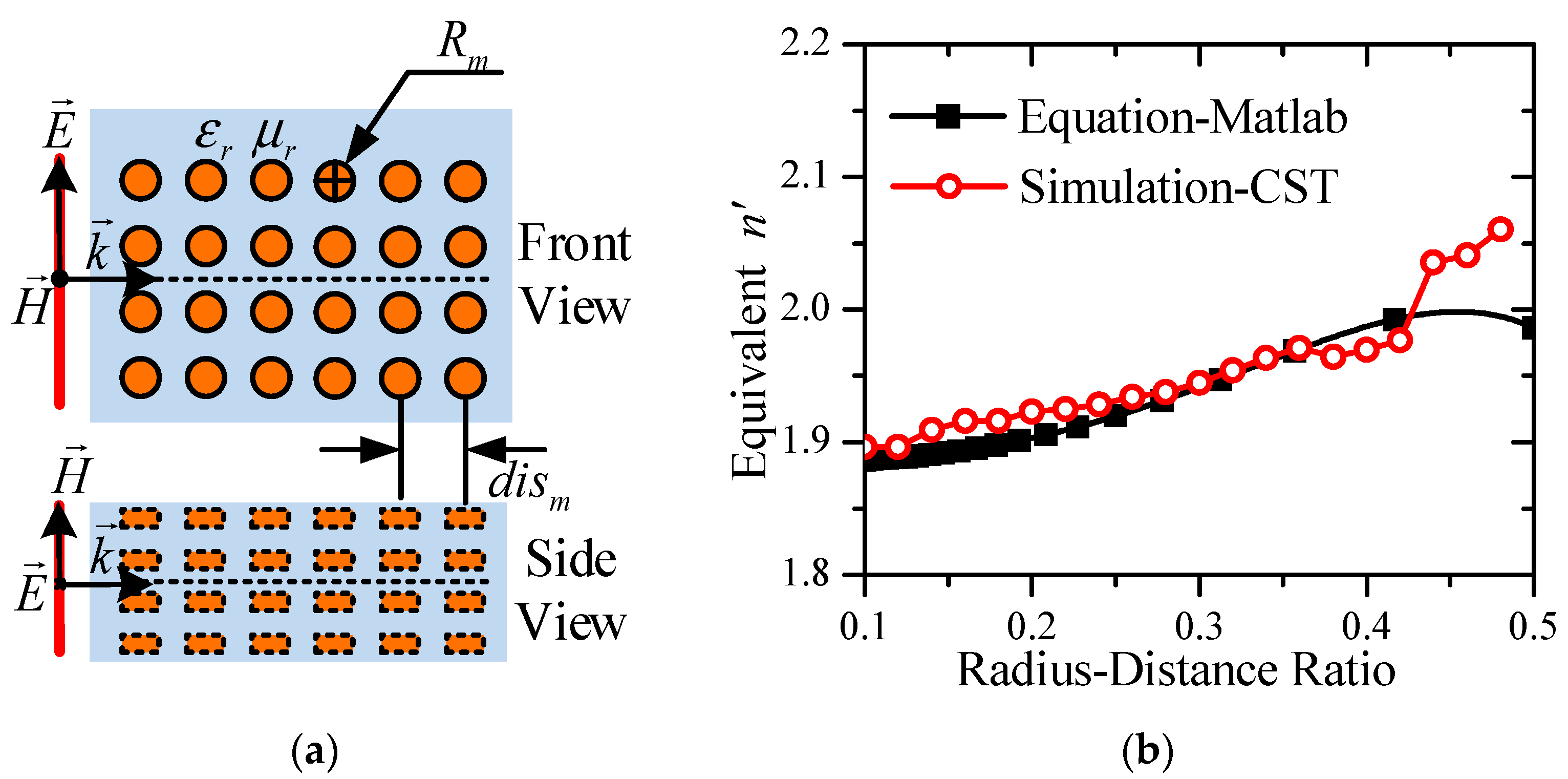
Multiple small metallic posts are uniformly placed into a medium with the relative permittivity and permeability of to form a metallic delay lens, with the post radius of and the center spacing of , as shown in Figure 2a. Similar to the derivation of equivalent permittivity and polarization characteristic of the ordinary medium, the small metallic post under an external electric field can be viewed as an equivalent dipole, and the relative permittivity of the metallic delay lens can be written as
where N is the number of small metallic posts per unit volume and is the electric polarization coefficient of the equivalent electric dipole.
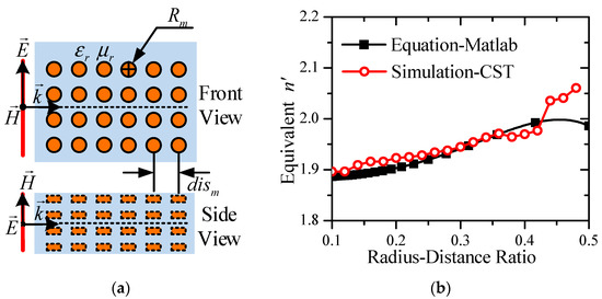
Figure 2.
Structural representation and equivalent parameters of the metallic delay lens. (a) Front view and side view of the metal post array, and (b) equivalent refractive index calculated from equation and by full-wave simulation.
When the magnetic field acts on the small metallic posts, the induced current on the surface of the metallic post is equivalent to a magnetic dipole. Therefore, the relative permeability can be obtained in the same analysis as:
where is the magnetic polarization coefficient of the equivalent magnetic dipole.
The equivalent refractive index of the metallic delay lens can be determined by the equivalent relative permittivity and permeability as:
Therefore, it is necessary to determine and to obtain the equivalent refractive index of the metallic delay lens.
To load in the radiation aperture of a TSA, the metallic delay lens should be constructed with a quasi-2D metal post array etched in the antenna substrate. Considering that the height of the substrate is relatively small, the metallic posts with the same height can be viewed as metallic disks for which the calculation formulas of the equivalent electric and magnetic polarization coefficient have been given in references as follows [39,40,41,42]:
By substituting (9) and N into (8), the equivalent refractive index of the metallic delay lens can be calculated by:
As indicated by (10), the equivalent refractive index of the metallic delay lens etched in a certain substrate is determined by the ratio of the radius to the center spacing of the posts.
Full-wave simulation has been carried out in CST to verify the theoretical equations. Corresponding to the antenna design, the metal post array with a height of 0.508 mm is etched into the medium of a Rogers 4003C laminate (relative permittivity and permeability of = 3.55 and = 1). The metal post array with 10 × 7 × 50 elements is modeled and simulated in CST, and a plane wave with the electric field parallel to the cross section of the posts is adopted as the source, as shown in Figure 2a. The equivalent refractive index then can be retrieved from the simulated results of the operating wavelength of the artificial medium. Figure 2b shows the calculated results of varying with different radius-spacing ratio from (10) and from full-wave simulation at 10 GHz. It can be seen clearly that the theoretical results agree well with the simulated results for the metal post array with the radius-spacing ratio below 0.42. The discrepancy for the cases with a larger radius-spacing ratio can be attributed to the non-ignorable interaction between adjacent posts. As pointed out in [39,41], a certain impact on the polarization coefficient will appear when the spacing between adjacent metallic objects is relatively small, because there is significant interaction between adjacent objects.
2.3. Time-Domain Performance of Metallic Delay Lens
As the proposed metallic delay lens is loaded in the TSA that is widely utilized in short-pulse applications, the investigation of the time-domain performance is necessary and is of importance. Fidelity is a widely used time-domain parameter to describe the characteristic of short-pulse networks and antennas by measuring the distortion between the input and output signals. The definition of the fidelity can be written as [43,44]:
where denotes the input or reference signal and denotes the output or the monitoring signal. The fidelity F is the maximum integration by varying transmission time delay between and .
To demonstrate the time-domain performance of the metal post array, the same model described in section B is simulated again and a differential Gaussian pulse with a spectrum of 2.8–30 GHz is adopted as the excitation signals for the plane wave source. According to the results shown in Figure 2b, the radius-spacing ratio is chosen as 0.36 and the radius of the posts is set to 0.5 mm in the simulation model.
The electric field signals at discrete points located on the central axis (the dotted line is shown in Figure 2a) of the metal post array are monitored to study the pulse fidelity, and the signal at the reference point being 10 mm away from the feed surface is chosen as the reference signal. As shown in Figure 3a, after 25 mm transmission from the reference point in the metallic delay lens, the monitoring signal S2 has a similar differential Gaussian main pulse to the reference signal S1, and the pulse waveform distortion is small. Figure 3b shows the fidelity between the reference signal and the monitoring signal at different positions from the reference point. It can be seen that the fidelity decreases with the increase of the transmission distance, and the pulse fidelity of the signals is 96% after a 25 mm transmission. The good time-domain performance of the metallic delay lens can be expected, because the equivalent refractive index of the lens is frequency-independent in theory, according to (10), and thus the propagation constant in the lens is linear with respect to the frequencies, which satisfies the distortionless conditions of the wave phase. Therefore, the proposed metallic delay lens will have a negligible effect on the short-pulse antennas.
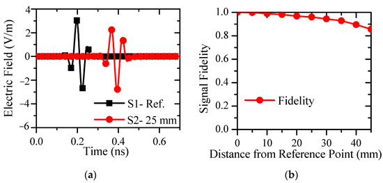
Figure 3.
Time-domain performance of the transmission signals in the metallic delay lens. (a) Comparison between reference signal and monitoring signal, and (b) fidelity for monitoring signals varying with different distance away from the reference point.
3. Design of PWTSA with Metamaterial-Based Lens
3.1. Tapered Slot Antenna Loaded with Lens
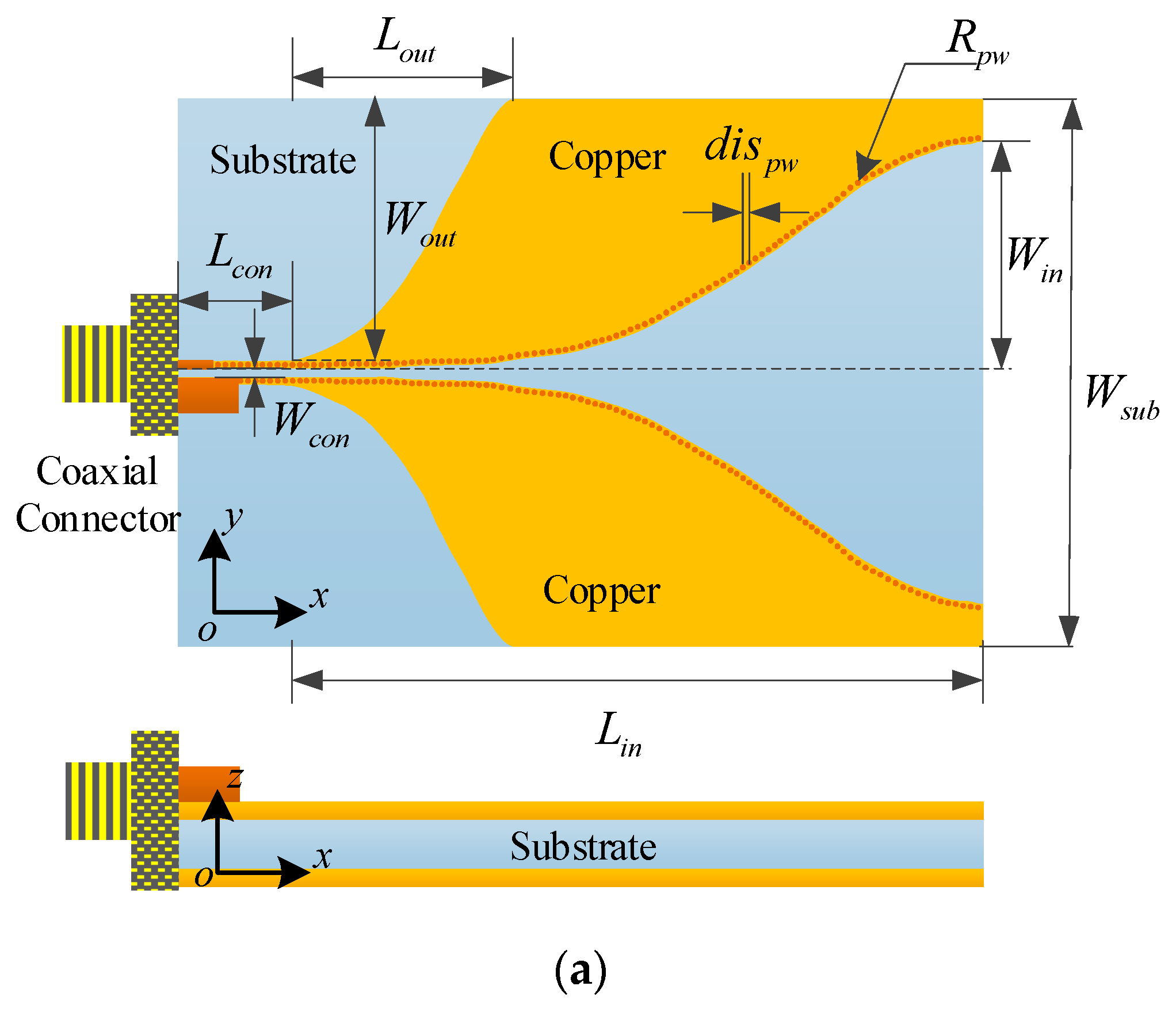
To evaluate the effect of the metallic delay lens on the gain and radiation improvement for tapered slot antennas operating in short-pulse applications, a TSA with an ultra-wide bandwidth should be designed as a basic reference antenna. A post-wall-structured tapered slot antenna, with two metalized via arrays aligned at the inner slot edges, presents a large bandwidth due to the large variation range of the characteristic impedance of the post-wall structures [5]. For the profile of the slot line, a Gaussian-tapered type has demonstrated better gain uniformity across the center of the passband [6,45], which is a proper candidate for studying the gain enhancement. Therefore, a post-wall-structured tapered slot antenna with the inner and outer profiles tapering on the basis of a Gaussian function is designed, as shown in Figure 4a.
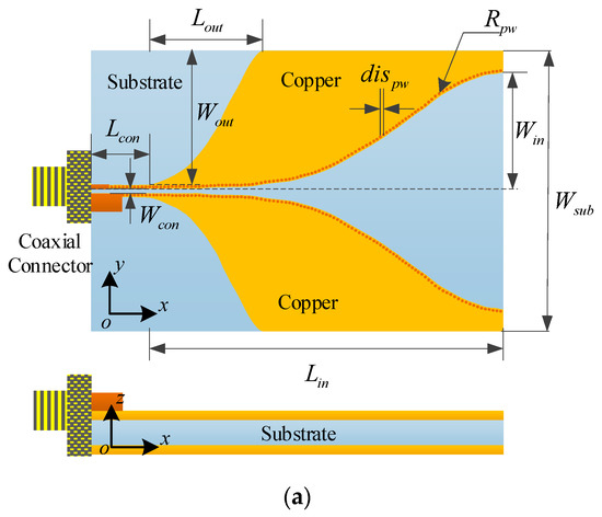

Figure 4.
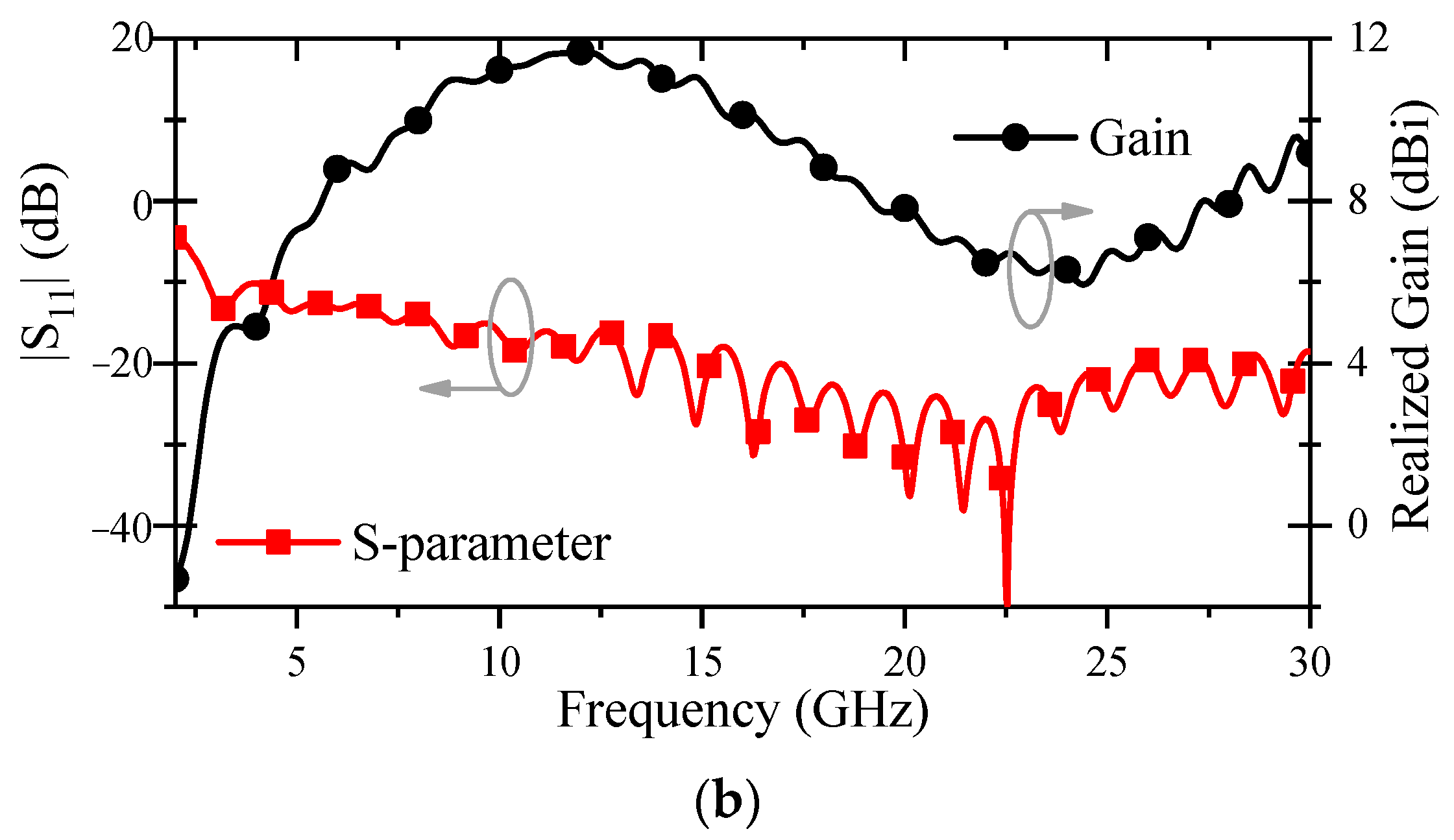
Configuration and radiation performance of the conventional PWTSA. (a) Geometric diagram and physical parameters, and (b) simulated |S11| and realized gain (Lcon = 9, Wcon = 0.2, Lin = 80, Win = 25, Lout = 30, Wout = 28.7, Wsub = 60, Rpw = 0.15, dispw = 0.8, unit: mm).
Figure 4a gives the front view and side view of the basic unloaded PWTSA with a planar size of 89 mm × 60 mm, and the Rogers 4003C laminate with a thickness of 0.508 mm and a relative permittivity of 3.55 is chosen as the substrate. The slot lines of the PWTSA are formed by two radiating copper patches printed on both sides of the substrate. Two arrays of metallic vias aligning along the slot edges are applied to connect the patches on opposite substrate surfaces to form the post-wall-structured slot which presents low characteristic impedance and thus can be fed by a coaxial connector directly. The post-wall-structured slot includes two parts, a constant width slot segment and a tapered slot segment. The inner tapered profile and the outer profile of the radiating patches are both defined by Gaussian functions as follows:
where , , , and denote the maximum amplitudes and the corresponding lengths of the inner and outer Gaussian profile curves, respectively.
Figure 4b shows the simulated |S11| and realized gain in the end-fire direction of the conventional PWTSA, with the optimized dimensions listed in the caption of Figure 4. As shown in Figure 4b, the PWTSA presents a wide −10 dB impedance bandwidth from 2.8 to 30 GHz and a maximum realized gain of 11.7 dBi at 12.1 GHz. The gain decreases at higher frequencies due to the splitting and shifting of the main lobe, placing severe restriction on the operating frequency range of this antenna.
3.2. PWTSA Loaded with Metallic Delay Lens
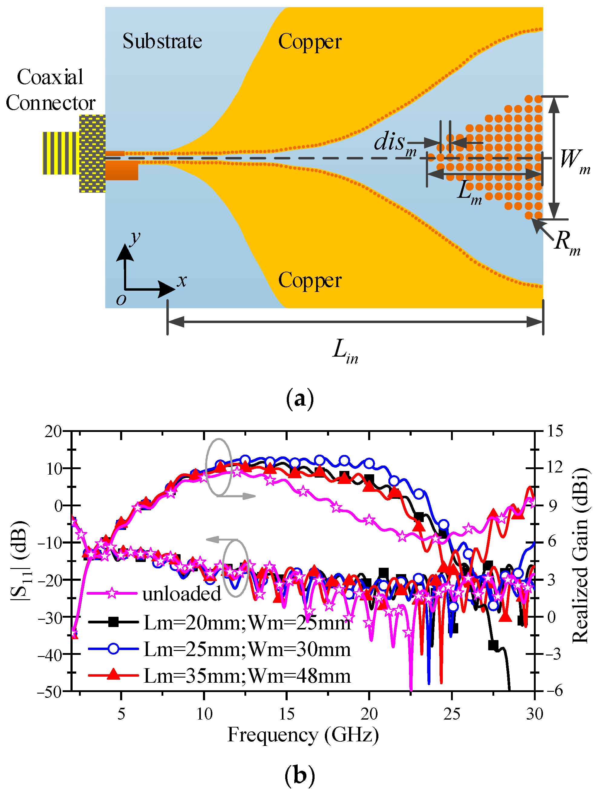
As discussed in Section 2, loading appropriate metallic delay lens in the radiation aperture region of a conventional PWTSA results in radiation improvement, because the phase plane of the passing EM waves is altered to be a uniform distribution. As illustrated in Figure 5a, the PWTSA designed in Figure 4 is loaded with a metallic delay lens composed of a hyperbolic metal post array, to pursue the radiation improvement with no increase to the antenna size, which makes it possible to improve the antenna performance while maintaining the compact feature. The length and width of the metallic delay lens are denoted by and , respectively. The posts are etched through the substrate with a post radius of and center spacing between adjacent posts of . According to the comparison shown in Figure 2b, the radius-spacing ratio of the posts is chosen as 0.36 and then the equivalent refractive index of the metallic delay lens can be calculated as . As a result, when the radius of the posts is set to = 0.5 mm, the center spacing can be worked out to be mm.
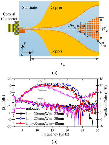
Figure 5.
Configuration and radiation performance of the PWTSA loaded with metallic delay lens. (a) Geometric diagram and physical parameters, and (b) simulated |S11| and realized gain with different lens dimensions.
Based on the optimized dimensions of the unloaded PWTSA listed in Figure 4, the length and width of the metallic delay lens can be determined by substituting the related parameter values into (3) and (5) as follows:
To study the loading effect of the metallic delay lens with different dimensions, simulations with lengths and widths of {(20, 25), (25, 30), (30, 32), (35, 34), (35, 48)} (unit: mm) were carried out and the results show that the radiation improvement is not the best for cases with too large or too small a lens size. The |S11| and realized gain of three typical cases are compared in Figure 5b. It can be found from Figure 5b that the PWTSAs loaded with metallic delay lens with different dimensions all show a higher realized gain than the unloaded PWTSA in the high frequency band, and the group with = 25 mm and = 30 mm achieves the best result. It can also be found that the S-parameters change slightly with the variation of the metallic delay lens sizes, since the loading structure placed in the radiation aperture region has little influence on the input impedance of the antenna.
3.3. PWTSA Loaded with Metamaterial-Based Lens
As given in the previous sections, the radiation aperture size of the PWTSA is = 50.2 mm and the width of the metallic delay lens is = 30 mm; there is a little area between the edges of the slot and the metallic delay lens, which can be further exploited.
The metallic delay lens placed symmetrically around the central axis of the tapered slot results in a reduction of the phase velocity of the passing EM waves due to the larger equivalent refractive index. In contrast, an air-hole array etched through the substrate can increase the phase velocity due to the smaller equivalent refractive index. Therefore, the proposed metallic delay lens cooperates with an airy acceleration region consisting of an air-hole array placed near the slot edges can produce a more uniform phase distribution with more obvious radiation improvement. The combination of the metallic delay lens and the airy acceleration region is relevantly termed as a metamaterial-based lens. The configuration of the PWTSA loaded with the metalens is shown in Figure 6. The radius of the air holes is set to = 0.5 mm and the center spacing between adjacent air holes is set to mm, based on the optimized simulation results.
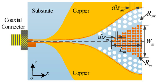
Figure 6.
Configuration of the PWTSA loaded with metalens (Lm = 25, Wm = 30, Rm = 0.5, dism = 1.4, Rair = 0.5, disair = 1.5, unit: mm).
To study the loading effects of the metalens on the radiation performance, the conventional unloaded PWTSA, the PWTSA loaded with the metallic delay lens, and the PWTSA loaded with the metalens are simulated and compared. For convenience of comparison, the three antennas are labeled as CA, MA, and MLA, respectively. The dimensions of the three PWTSAs are the same, as discussed and listed in previous sections.
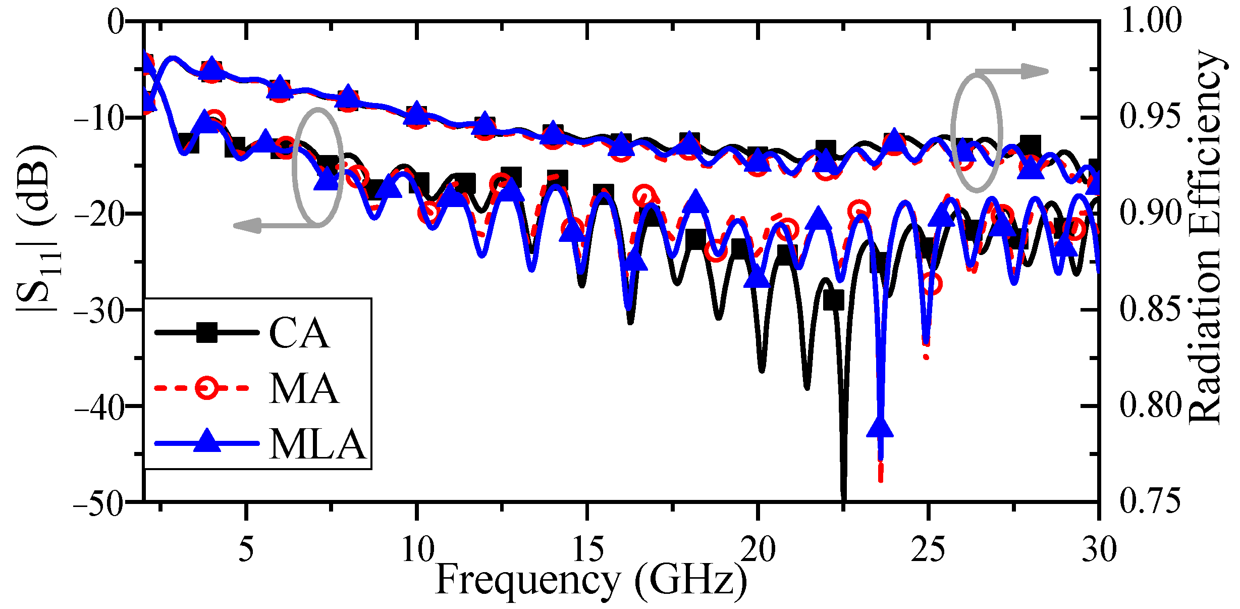
Figure 7 gives the comparison of |S11| and the radiation efficiency between the three PWTSAs. As shown in Figure 7, the impedance bandwidths for |S11| < −10 dB are all from 2.8 to 30 GHz for the three antennas. This means that the loading structures, whether metallic delay lens or metalens, have little effects on the impedance matching when they are placed in the radiation aperture of the PWTSA. Similarly, the radiation efficiency of the three antennas varies very little over the entire operating frequency band, which are all greater than 92%.
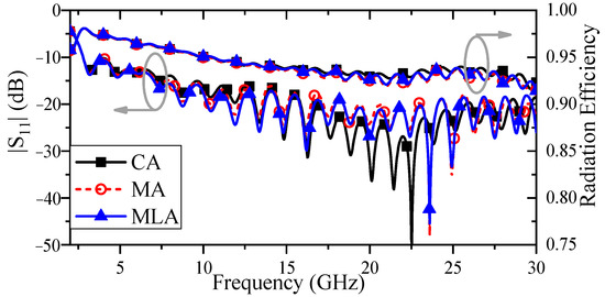
Figure 7.
Comparison of |S11| and radiation efficiency between the three PWTSAs.
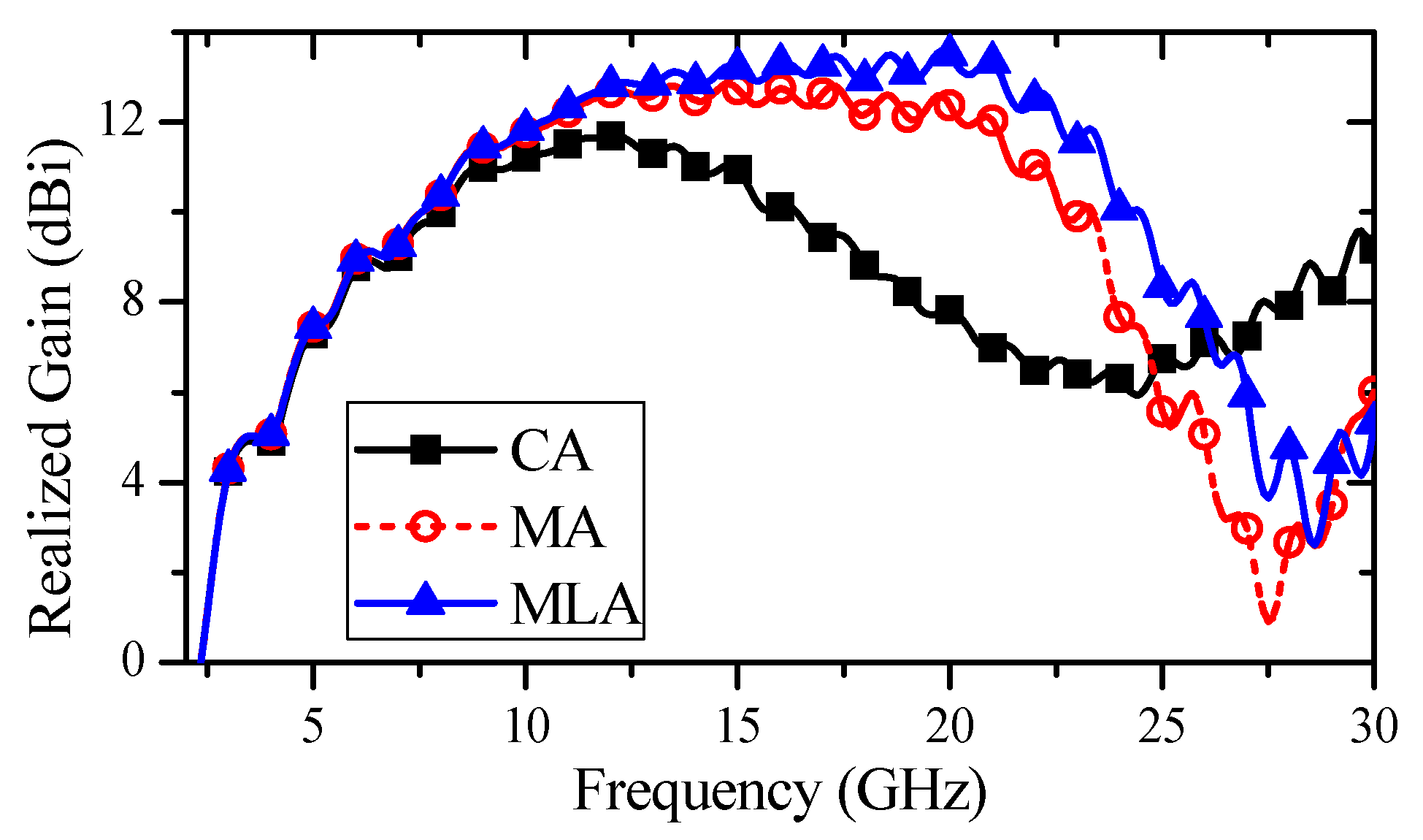
From the discussion given in previous sections, the phase adjustment by the metallic delay lens and the airy acceleration region is more effective in the high frequency band because the phase difference in the aperture surface is larger in this band. It can be verified by comparing the radiation performance between the three antennas shown in Figure 8 and Figure 9.
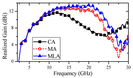
Figure 8.
Comparison of realized gain in the end-fire direction between the three PWTSAs.
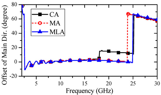
Figure 9.
The offset of the main lobe direction from the end-fire direction for the three PWTSAs.
As shown in Figure 8, the realized gains in the end-fire direction of the MA and MLA are improved significantly in the high frequency band with a wider gain bandwidth compared to the unloaded CA. Due to the loading of the metallic delay lens, the realized gain of the MA is increased by about 0.5–5.14 dB from 9 to 24.7 GHz, and the realized gain of the MLA is increased by 0.5–6.4 dB from 9 to 26 GHz, due to the cooperation of the metallic delay lens and the airy acceleration region.
Figure 9 gives the offset between the main lobe direction and the end-fire direction for the three PWTSAs. It can be found that the offset of the CA increases to 15° in the frequency band above 18 GHz, which indicates the shifting and splitting of the main lobe in the high frequency band. After loading a metallic delay lens in the MA, the position of the offset jump is delayed from 18 to 23.9 GHz. Moreover, based on the loading of the metallic delay lens and the airy acceleration region, the position of the offset jump for the MLA is further pushed with the offset being confined to 2° until 24.9 GHz, which indicates that the loaded metalens can improve the radiation stability of the PWTSA dramatically.
The contours of the electric field at 20 GHz in the E-plane for the unloaded reference CA and the MLA with a metalens are illustrated in Figure 10a,b, respectively. It can be seen that the electric field of the MLA shows a flatter wavefront than that of the unloaded CA, which means that the loading structures play an effective role in the gain enhancement of the PWTSA.
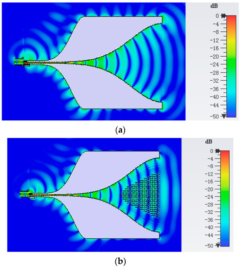
Figure 10.
The electric field distribution at 20 GHz for the PWTSAs. (a) CA unloaded, and (b) MLA loaded with the metalens.
4. Design of PWTSA with Metamaterial-Based Lens
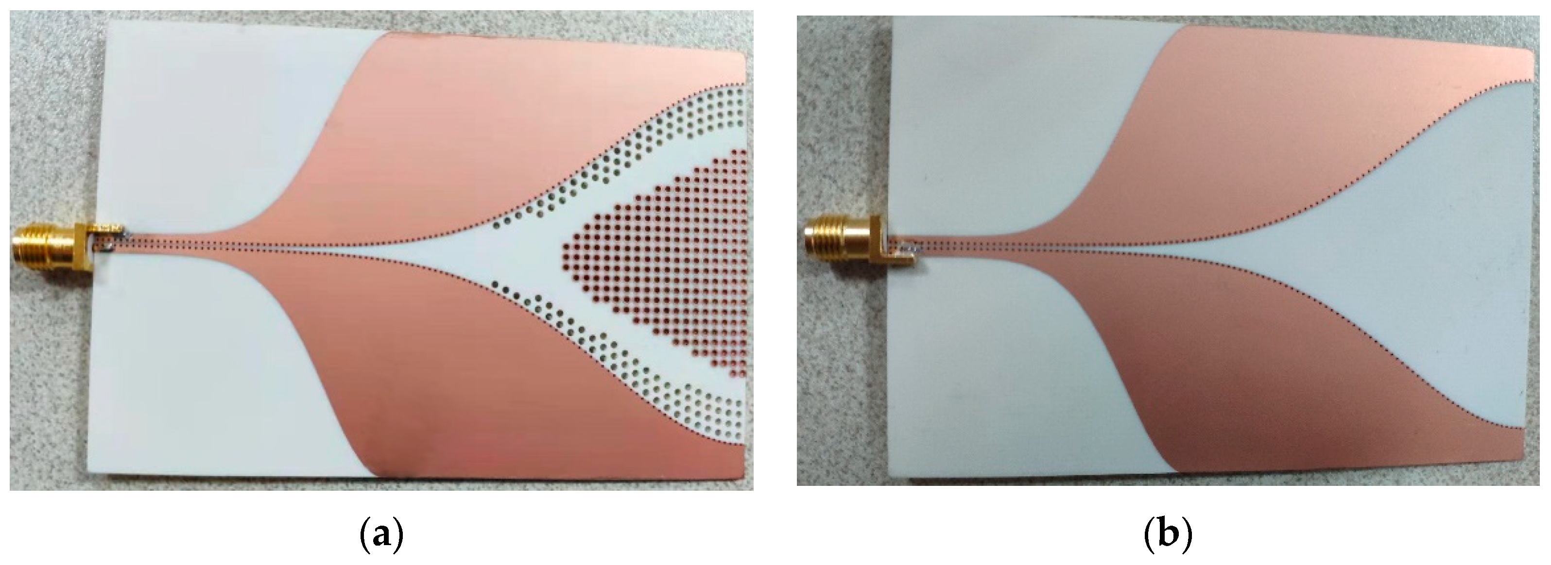
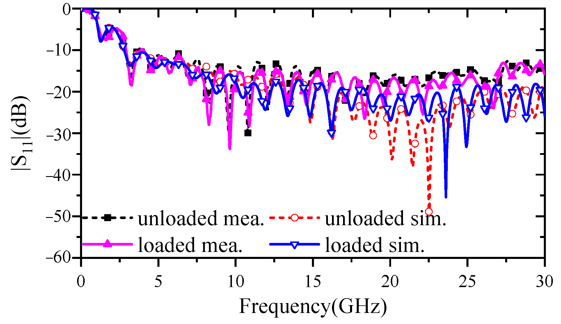
Based on the simulated results discussed above, a prototype PWTSA loaded with a metalens composed of metallic delay lens and an airy acceleration region is designed and fabricated, as shown in Figure 11a. For comparison, the unloaded PWTSA with the same dimensions is also fabricated and is depicted in Figure 11b. The reflection coefficient of the fabricated antennas was measured using an Agilent network analyzer N5224A. As shown in Figure 12, the measured and the simulated S-parameters both show that the loaded PWTSA and the unloaded reference PWTSA have a similar −10 dB impedance bandwidth which is from 2.8 to 30 GHz. It indicates that the loading structures bring no additional reflection.

Figure 11.
Photographs of the fabricated PWTSAs. (a) PWTSA loaded with metalens, and (b) unloaded reference PWTSA.
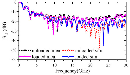
Figure 12.
Simulated and measured |S11| of the PWTSAs with and without the metalens.
The realized gain of the proposed loaded PWTSA and the unloaded reference PWTSA were measured and compared with the simulated ones, as shown in Figure 13. Based on the simulated results, the realized gain of the PWTSA was improved in the range from 9 to 26 GHz with a maximum enhancement of 6.4 dB at 20.9 GHz by loading the metalens, while the measured results of the loaded PWTSA showed an enhancement of 0.5–6.2 dB from 7.32 to 24 GHz with a maximum quantity of 6.2 dB at 20.4 GHz. Therefore, the improvement of the gain provided by the loading metalens for the PWTSA in the high frequency band is dramatical, though the enhancement and the corresponding frequency band given by simulation and measurement are slightly different in specific values. In addition, there is a mismatch between the simulated results and the measured results in the high frequency band, mainly due to the loss of the SMA connector and antenna installation in measurements. These effects for the measured results are especially obvious at high frequencies, above 10 GHz.
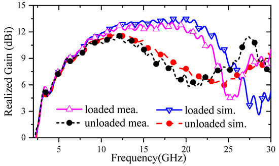
Figure 13.
Simulated and measured realized gain of the PWTSAs with and without the metalens.
Figure 14 shows the cross-polarization levels of the loaded PWTSA and the unloaded reference PWTSA based on the simulation and the measurement. It can be seen from the measured results that the cross-polarization levels of the loaded PWTSA are below −20 dB across the band of 2.8 to 25.9 GHz, which is lower than that of the unloaded one, especially in the high frequency band. It means that the loading of the metalens is not deleterious to the cross-polarization level when enhancing the gain of the PWTSA.
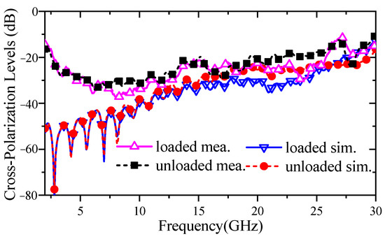
Figure 14.
Simulated and measured cross-polarization levels of the PWTSAs with and without the metalens.
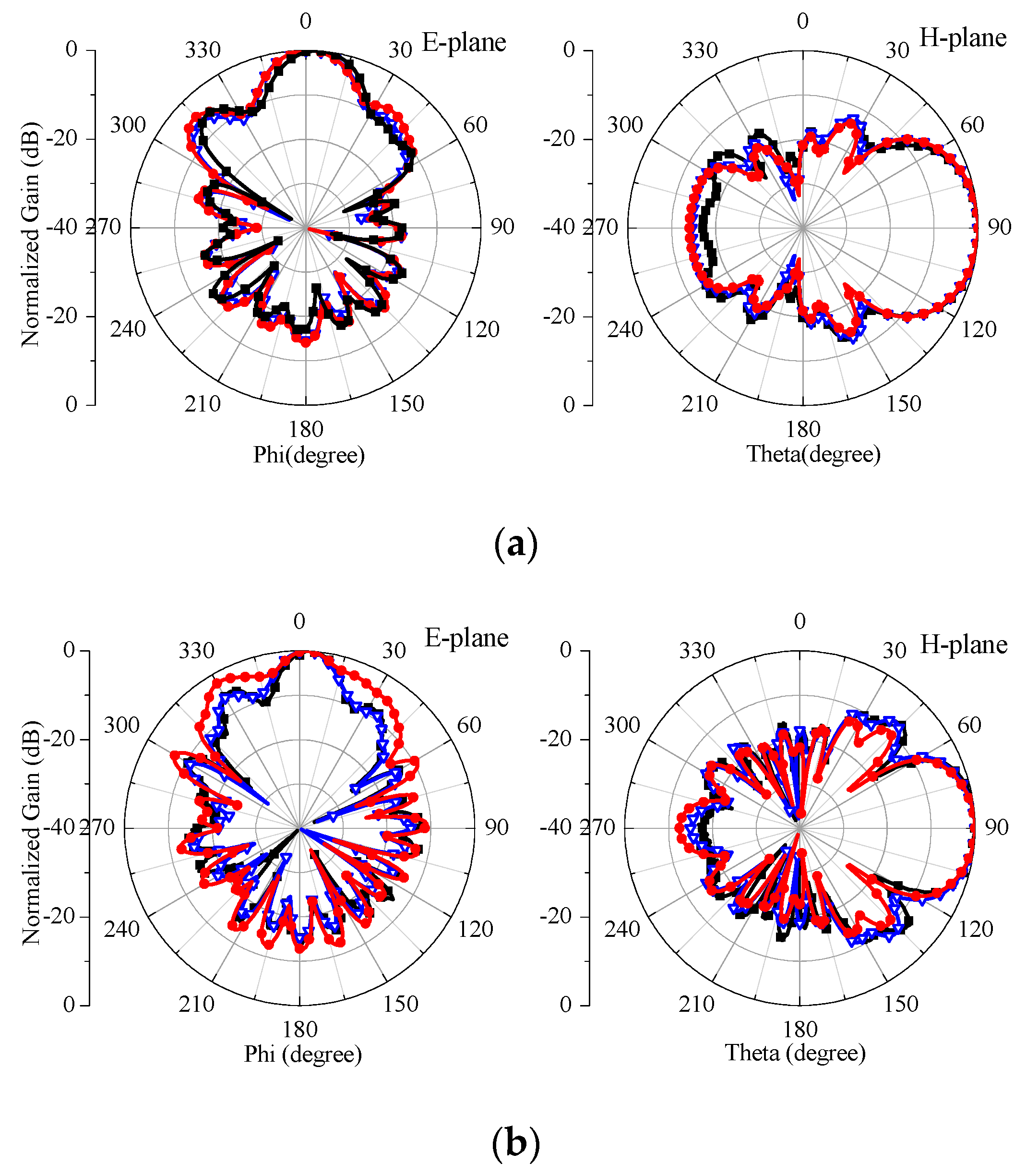
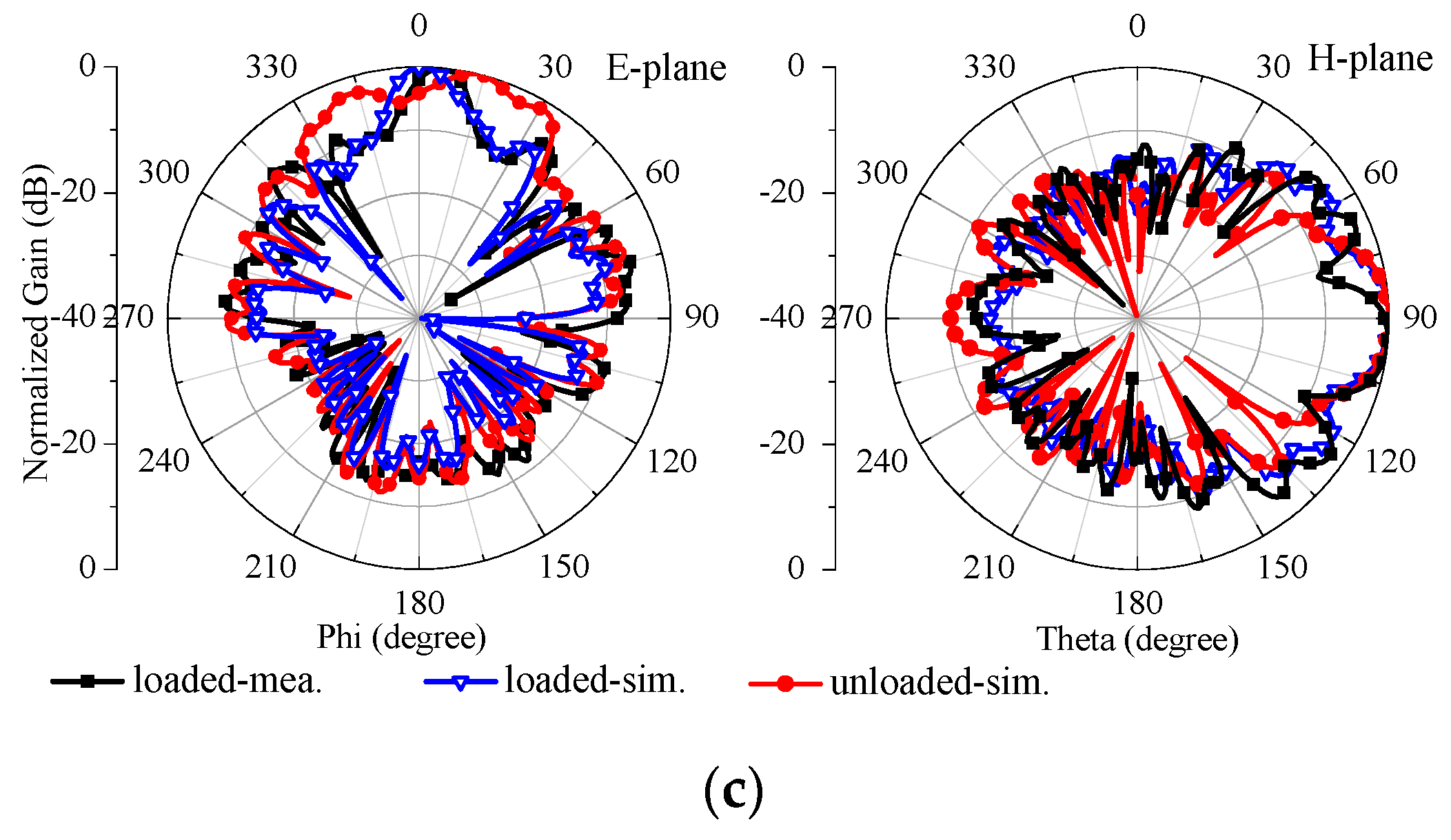
The normalized radiation patterns of the proposed loaded PWTSA obtained in measurement and simulation are found in good agreement, as shown in Figure 15. To verify the loading effect of the metalens, the simulated radiation patterns of the unloaded reference PWTSA is also shown in Figure 15. It can be found from Figure 15a that the radiation patterns of the two PWTSAs are almost the same at 10 GHz both in the E-plane and the H-plane. Along with the increase of the frequency, the 3 dB main lobe width in the E-plane is narrowed and the side lobe level (SLL) is decreased slightly for the loaded PWTSA, while the main lobe of the unloaded PWTSA is shifted and broadened with large SLLs, as shown in Figure 15b,c. The detailed comparison of the radiation patterns between the two PWTSAs is shown in Table 1, which demonstrates the gain enhancement and the preferable radiation stability performance by the loading of the metalens for the PWTSA.
Figure 15.
Simulated and measured radiation patterns of the PWTSAs with and without the metalens. (a) At 10 GHz, (b) at 15 GHz, and (c) at 21 GHz.

Table 1.
Radiation pattern parameters for two PWTSAs.
To investigate the time-domain performance of the proposed antenna, two identical loaded PWTSAs were placed 0.5 m apart along the end-fire direction and the transmission signal under the co-polarization condition were measured by using a vector network analyzer. For comparison, the same setup and measurement were made for the unloaded reference PWTSAs. A Gaussian pulse with a spectrum from DC to 30 GHz was utilized as the excitation. Figure 16 gives the measured transmission signals of the loaded antenna system and the unloaded one. It can be seen that the two signals present similar waveforms with a differential Gaussian main pulse and a small tailing effect. It means that the metalens shows a negligible effect on the waveform distortion, which has been discussed in Section 2. Therefore, the proposed loaded PWTSA can be viewed as a good candidate for short-pulse applications.
Figure 16.
Measured received signals for a transceiver system with and without the metalens.
5. Conclusions
In this contribution, a post-wall-structured tapered slot antenna with a metalens loaded in the radiation aperture was proposed for wideband radiation enhancement. The metallic delay lens of the metalens etched around the central axis of the aperture slowed the passing EM waves, while the airy acceleration region placed near the slot edges of the aperture increased the phase velocity. Therefore, the metalens modified the phase distribution of the EM waves for an enhanced gain by up to 6.4 dB ranging from 9 to 26 GHz, and stable radiation with the shift of the main lobe being confined to 2° below 24.9 GHz. In addition, the metalens showed good time-domain performance and thus the loaded PWTSA presented high fidelity short-pulse radiation capabilities. Consequently, the proposed metalens is suitable to enhance the radiation performance of tapered slot antennas in short-pulse applications and ultra-wideband communication systems.
Author Contributions
Conceptualization, Y.Y. and S.L.; investigation, Y.Y. and S.L.; project administration, S.L.; data curation, Q.Z.; formal analysis, Y.Y. and Q.Z.; writing, Y.Y. and Q.Z. All authors have read and agreed to the published version of the manuscript.
Funding
This research was funded by National Natural Science Foundation of China under Grant 61801116.
Conflicts of Interest
The authors declare no conflict of interest.
References
- Gibson, P.J. The vivaldi aerial. In Proceedings of the 9th European Microwave Conference, Brighton, UK, 17–20 September 1979; pp. 101–105. [Google Scholar]
- Janaswamy, R.; Schaubert, D.H. Analysis of the tapered slot antenna. IEEE Trans. Antennas Propag. 1987, 35, 1058–1065. [Google Scholar] [CrossRef]
- Yin, X.; Su, Z.; Hong, W.; Cui, T.J. An ultra wideband tapered slot antenna. In Proceedings of the IEEE Antennas and Propagation Society International Symposium, Washington, DC, USA, 3–8 July 2005; pp. 516–519. [Google Scholar]
- Yin, X.; Wang, Q.; Wang, C.; Shen, G.; Zhang, J.; Hong, W. A resistive loaded tapered slot antenna for ground penetrating radar. Mod. Radar 2006, 28, 58–68. [Google Scholar]
- Li, S.; Yin, X.; Zhao, H.; Qi, H. Postwall slotline and its application in design of short-pulse tapered slot antennas. IEEE Trans. Antennas Propag. 2015, 63, 3400–3409. [Google Scholar] [CrossRef]
- Yang, M.; Yin, X.; Li, Y.; Liu, L. Ultra-wideband planar Gaussian tapered rhombic antenna for short pulse applications. IEEE Antennas Wirel. Propag. Lett. 2016, 15, 48–51. [Google Scholar] [CrossRef]
- Zhu, S.; Liu, H.; Chen, Z.; Wen, P. A compact gain-enhanced Vivaldi antenna array with suppressed mutual coupling for 5G mmWave application. IEEE Antennas Wirel. Propag. Lett. 2018, 17, 776–779. [Google Scholar] [CrossRef]
- Chen, H.; Zhang, Q.; Gao, J.; Li, S.; Zhao, H.; Yin, X. Ultra-wideband reflectionless tapered slotline antenna with resistive absorption structure. In Proceedings of the 2019 International Symposium on Antennas and Propagation (ISAP), Xi’an, China, 27–30 October 2019; pp. 1–3. [Google Scholar]
- Yang, G.; Ye, S.; Zhang, F.; Ji, Y.; Zhang, X.; Fang, G. Dual-Polarized Dual-Loop Double-Slot Antipodal Tapered Slot Antenna for Ultra-Wideband Radar Applications. Electronics 2021, 10, 1377. [Google Scholar] [CrossRef]
- Kota, K.; Shafai, L. Gain and radiation pattern enhancement of balanced antipodal Vivaldi antenna. Electron. Lett. 2011, 47, 303–304. [Google Scholar] [CrossRef]
- Wang, Y.; Wang, G.; Zong, B. Directivity improvement of Vivaldi antenna using double-slot structure. IEEE Antennas Wirel. Propag. Lett. 2013, 12, 1380–1383. [Google Scholar] [CrossRef]
- Molaei, A.; Kaboli, M.; Mirtaheri, S.A.; Abrishamian, M.S. Dielectric lens balanced antipodal Vivaldi antenna with low cross-polarisation for ultra-wideband applications. IET Microw. Antennas Propag. 2014, 8, 1137–1142. [Google Scholar] [CrossRef]
- Moosazadeh, M.; Kharkovsky, S. A compact high-gain and front-to-back ratio elliptically tapered antipodal Vivaldi antenna with trapezoid-shaped dielectric lens. IEEE Antennas Wirel. Propag. Lett. 2016, 15, 552–555. [Google Scholar] [CrossRef]
- Kim, S.; Yu, H.; Choi, K.; Choi, D. Analysis of tapered slot antenna with high gain for 2D indoor wireless positioning. IEEE Access 2019, 7, 54312–54320. [Google Scholar] [CrossRef]
- Yang, Z.; Guo, L.; Yao, C.; Zhang, Q.; Xu, Z.; Guo, M.; Wang, Z. Ultrawideband antipodal tapered slot antenna with gradient refractive index metamaterial lens. IEEE Antennas Wirel. Propag. Lett. 2019, 18, 2741–2745. [Google Scholar] [CrossRef]
- Briqech, Z.; Sebak, A.; Denidni, T.A. Wide-scan MSC-AFTSA array-fed grooved spherical lens antenna for millimeter-wave MIMO applications. IEEE Trans. Antennas Propag. 2016, 64, 2971–2980. [Google Scholar] [CrossRef]
- Amiri, M.; Tofigh, F.; Ghafoorzadeh-Yazdi, A.; Abolhasan, M. Exponential antipodal Vivaldi antenna with exponential dielectric lens. IEEE Antennas Wirel. Propag. Lett. 2017, 16, 1792–1795. [Google Scholar] [CrossRef]
- Nashuha, S.H.; Lee, G.H.; Kumar, S.; Choi, H.C.; Kim, K.W. Ultra-Wideband Trapezoidal Log-Periodic Antenna Integrated with an Elliptical Lens. Electronics 2020, 9, 2169. [Google Scholar] [CrossRef]
- Erfani, E.; Niroo-Jazi, M.; Tatu, S. A high-gain broadband gradient refractive index metasurface lens antenna. IEEE Trans. Antennas Propag. 2016, 64, 1968–1973. [Google Scholar] [CrossRef]
- Palmeri, R.; Isernia, T. Inverse Design of Artificial Materials Based Lens Antennas through the Scattering Matrix Method. Electronics 2020, 9, 559. [Google Scholar] [CrossRef] [Green Version]
- Wang, J.; Cui, W.; Zhou, Y.; Liu, R.; Wang, M.; Fan, C.; Zheng, H.; Li, E. Design of Wideband Antenna Array with Dielectric Lens and Defected Ground Structure. Electronics 2021, 10, 2066. [Google Scholar] [CrossRef]
- Wang, N.; Fang, M.; Chou, H.; Qi, J.; Xiao, L. Balanced antipodal Vivaldi antenna with asymmetric substrate cutout and dual-scale slotted edges for ultrawideband operation at millimeter-wave frequencies. IEEE Trans. Antennas Propag. 2018, 66, 3724–3729. [Google Scholar] [CrossRef]
- Liu, P.; Zhu, X.; Jiang, Z.H.; Zhang, Y.; Tang, H.; Hong, W. A compact single-layer Q-band tapered slot antenna array with phase-shifting inductive windows for endfire patterns. IEEE Trans. Antennas Propag. 2019, 67, 169–178. [Google Scholar] [CrossRef]
- Teni, G.; Zhang, N.; Qiu, J.; Zhang, P. Research on a novel miniaturized antipodal Vivaldi antenna with improved radiation. IEEE Antennas Wirel. Propag. Lett. 2013, 12, 417–420. [Google Scholar] [CrossRef]
- Moosazadeh, M.; Kharkovsky, S.; Case, J.T.; Samali, B. Antipodal Vivaldi antenna with improved radiation characteristics for civil engineering applications. IET Microw. Antennas Propag. 2017, 11, 796–803. [Google Scholar] [CrossRef]
- Zhou, B.; Cui, T.J. Directivity enhancement to Vivaldi antennas using compactly anisotropic zero-index metamaterials. IEEE Antennas Wirel. Propag. Lett. 2021, 10, 326–329. [Google Scholar] [CrossRef]
- Sun, M.; Chen, Z.N.; Qing, X. Gain enhancement of 60-GHz antipodal tapered slot antenna using zero-index metamaterial. IEEE Trans. Antennas. Propag. 2013, 61, 1741–1746. [Google Scholar] [CrossRef]
- Zhu, S.; Liu, H.; Wen, P. A new method for achieving miniaturization and gain enhancement of Vivaldi antenna array based on anisotropic metasurface. IEEE Trans. Antennas Propag. 2019, 67, 1952–1956. [Google Scholar] [CrossRef]
- Cheng, H.; Yang, H.; Li, Y.; Chen, Y. A compact Vivaldi antenna with artificial material lens and sidelobe suppressor for GPR applications. IEEE Access 2020, 8, 64056–64063. [Google Scholar] [CrossRef]
- Zhang, X.; Sun, W.; Chen, J. Millimeter-wave ATS antenna with wideband-enhanced endfire gain based on coplanar plasmonic structures. IEEE Antennas Wirel. Propag. Lett. 2019, 18, 826–830. [Google Scholar] [CrossRef]
- Eichenberger, J.; Yetisir, E.; Ghalichechian, N. High-gain antipodal Vivaldi antenna with pseudoelement and notched tapered slot operating at (2.5 to 57) GHz. IEEE Trans. Antennas Propag. 2019, 67, 4357–4366. [Google Scholar] [CrossRef]
- El-Hameed, A.S.A.; Barakat, A.; Abdel-Rahman, A.B.; Allam, A.; Pokharel, R.K. A 60-GHz double-Y balun-fed on-chip Vivaldi antenna with improved gain. In Proceedings of the 27th International Conference on Microelectronics (ICM), Casablanca, Morocco, 20–23 December 2015; pp. 307–310. [Google Scholar]
- Umar, S.M.; Khan, W.; Ullah, S.; Ahmad, F. Gain enhancement technique in Vivaldi antenna for 5G communication. In Proceedings of the 2nd International Conference of Computing, Mathematics and Engineering Technologies (iCoMET), Sukkur, Pakistan, 30–31 January 2019; pp. 1–4. [Google Scholar]
- Zhang, J.; Lan, H.; Liu, M.; Yang, Y. A handheld nano through-wall radar locating with the gain-enhanced Vivaldi antenna. IEEE Sens. J. 2020, 20, 4420–4429. [Google Scholar] [CrossRef]
- Chen, L.; Lei, Z.Y.; Yang, R.; Fan, J.; Shi, X.W. A broadband artificial material for gain enhancement of antipodal tapered slot antenna. IEEE Trans. Antennas Propag. 2015, 63, 395–400. [Google Scholar] [CrossRef]
- Yesilyurt, O.; Turhan-Sayan, G. Metasurface lens for ultra-wideband planar antenna. IEEE Trans. Antennas Propag. 2020, 68, 719–726. [Google Scholar] [CrossRef]
- Sang, L.; Wu, S.; Liu, G.; Wang, J.; Huang, W. High-gain UWB Vivaldi antenna loaded with reconfigurable 3-D phase adjusting unit lens. IEEE Antennas Wirel. Propag. Lett. 2020, 19, 322–326. [Google Scholar] [CrossRef]
- Guo, L.; Yang, H.; Zhang, Q.; Deng, M. A compact antipodal tapered slot antenna with artificial material lens and reflector for GPR applications. IEEE Access 2018, 6, 44244–44251. [Google Scholar] [CrossRef]
- Schelkunoff, S.A.; Friis, H.T. Antennas: Theory and Practice; John Wiley & Sons: New York, NY, USA, 1952. [Google Scholar]
- Jasik, H. Antenna Engineering Handbook; McGraw-Hill: New York, NY, USA, 1961. [Google Scholar]
- Collin, R.E. Field Theory of Guided Waves; McGraw-Hill: New York, NY, USA, 1960. [Google Scholar]
- Kock, W.E. Metallic delay lenses. Bell Syst. Tech. J. 1948, 27, 58–82. [Google Scholar] [CrossRef]
- Chen, Z.N.; Wu, X.H.; Li, H.F.; Yang, N.; Chia, M.Y.W. Considerations for source pulses and antennas in UWB radio systems. IEEE Trans. Antennas Propag. 2004, 52, 1739–1748. [Google Scholar] [CrossRef]
- Li, S.; Yin, X.; Wang, L.; Zhao, H.; Liu, L.; Zhang, M. Time-domain characterization of short-pulse networks and antennas using signal space method. IEEE Trans. Antennas Propag. 2014, 62, 1862–1871. [Google Scholar] [CrossRef]
- Ebnabbasi, K.; Busuioc, D.; Birken, R.; Wang, M. Taper design of Vivaldi and co-planar tapered slot antenna (TSA) by Chebyshev transformer. IEEE Trans. Antennas Propag. 2012, 60, 2252–2259. [Google Scholar] [CrossRef]


Publisher’s Note: MDPI stays neutral with regard to jurisdictional claims in published maps and institutional affiliations. |
© 2021 by the authors. Licensee MDPI, Basel, Switzerland. This article is an open access article distributed under the terms and conditions of the Creative Commons Attribution (CC BY) license (https://creativecommons.org/licenses/by/4.0/).