Abstract
This paper addresses the Optimal Power Flow (OPF) problem in Direct Current (DC) networks by considering the integration of Distributed Generators (DGs). In order to model said problem, this study employs a mathematical formulation that has, as the objective function, the reduction in power losses associated with energy transport and that considers the set of constraints that compose DC networks in an environment of distributed generation. To solve this mathematical formulation, a master–slave methodology that combines the Salp Swarm Algorithm (SSA) and the Successive Approximations (SA) method was used here. The effectiveness, repeatability, and robustness of the proposed solution methodology was validated using two test systems (the 21- and 69-node systems), five other optimization methods reported in the specialized literature, and three different penetration levels of distributed generation: 20%, 40%, and 60% of the power provided by the slack node in the test systems in an environment with no DGs (base case). All simulations were executed 100 times for each solution methodology in the different test scenarios. The purpose of this was to evaluate the repeatability of the solutions provided by each technique by analyzing their minimum and average power losses and required processing times. The results show that the proposed solution methodology achieved the best trade-off between (minimum and average) power loss reduction and processing time for networks of any size.
1. Introduction
1.1. Direct Current Networks and the Optimal Power Flow Problem
As a result of the rapid growth of the world population and increased energy (mostly electricity) consumption in the last two centuries, the global demand for energy has risen considerably. There is, therefore, the need to expand the ways of producing and distributing electrical energy [1,2,3,4,5,6] while seeking to reduce the associated environmental impact and provide end users with a high-quality and reliable electrical service. In this regard, various authors, electric power sectors, and countries have striven to promote the development of energy management technologies and strategies to increase electricity production worldwide and diversify energy mixes, as well as the development and application of new energy distribution technologies (e.g., distributed generators [7,8,9,10]) and energy storage elements (e.g., batteries, capacitors, ultracapacitors, and superinductors) [11,12,13,14]. In addition, they have returned to conventional energy transport systems and strengthened them using modern technologies, as in the case of Direct Current (DC) networks for electricity supply [15].
In recent years, advances in power electronic devices have driven the development and widespread use of DC networks in both power transmission and distribution systems [16,17]. These networks have various advantages over Alternating Current (AC) networks [16], including (i) no need for reactive element analysis, (ii) lower investment and operating costs associated with the installation and maintenance of the network, and (ii) easy integration of energy generation and storage devices into the grid because the main distributed generation devices (solar panels), batteries, and electrical loads operate in DC.
Like AC networks, DC networks are mainly composed of a slack generator, Distributed Generators (DGs), power distribution lines, and electrical loads [18]. Hence, once the electrical network is designed, strategies for dispatching DGs should be proposed to deliver the highest number of (economic, technical, or environmental [19]) benefits to both network operators and users connected to the DC network. This need is referred to, in the literature, as the Optimal Power Flow (OPF) problem, which entails determining the power level to be injected by the DGs installed in the network in order to meet the goal that network operators have established. In this study, the objective function is the reduction in power losses associated with electrical energy transmission. This indicator was selected due to its widespread use to validate the effectiveness and robustness of the techniques proposed to solve the OPF problem in DC networks [20].
To solve the OPF problem, it is generally divided into two stages. The first stage seeks to determine the optimal power levels to be injected by the DGs located in the network, which are directly linked to their maximum and minimum power levels. The second stage aims to solve the load flow problem in order to identify the impact of each power level injected by the DGs into the network on the objective function and the technical and operational constraints of the network (e.g., power balance, voltage profiles, power limits [21]). Thus, methodologies that find high-quality solutions in short processing times should be implemented to solve the problem mentioned above. To that end, different authors have proposed using optimization methods capable of finding high-quality solutions on a recurring basis within any given dimension in a specific problem (in this case, the OPF problem) [22,23] by means of techniques based on sequential programming that can be replicated in any programming language [7]. These optimization methodologies are often selected to encourage the adoption of open-source software that can be employed in embedded systems in the near future, thus reducing the complexity and costs associated with the use of specialized software.
1.2. State-of-the-Art on the Optimal Power Flow Problem in Direct Current Networks
Since DC networks must operate within the right power levels for the DGs in order to meet the goals defined by users and network operators, various authors have proposed (i) energy management strategies that are mainly based on intelligent algorithms and use commercial software and (ii) energy management strategies based on sequential programming, which makes it possible to find the optimal power levels for the DGs in known power demand scenarios [20].
A number of studies have been conducted on the strategies that use commercial software [24,25,26]. These studies employed, as the objective function, the minimization of power losses associated with energy transport in DC networks and considered all the constraints of this type of electrical system in a scenario of distributed generation. After analyzing these studies, it can be concluded that using commercial software increases the complexity of the problem and the costs associated with the solution, thus limiting the application of the solution methodologies proposed by their authors. In [24], the MOSEK optimization software was used to implement a convex relaxation method based on second-order conic programming. In such research, the authors only used a 16-node DC network. Likewise, in [25], the Continuous Genetic Algorithm (CGA) was implemented using the GAMS/CONOPT software. The authors of such study did not consider processing times and only employed a 10-node test system to validate their results, which does not allow an adequate assessment of the impact of their proposed solution methodology. In [26], the authors used convex quadratic sequential programming models and the 10- and 21-node test systems. They took into account processing times but not the standard deviation of the implemented techniques, which is an important parameter to determine how dispersed the results obtained by each solution methodology are. All of these studies employed small test systems (10, 16, and 21 nodes), which provide little information, and did not consider the currents through the lines and the worst voltage at the nodes of the system.
With the aim of proposing methods based on sequential programming and eliminating the need for commercial software, various methodologies that use optimization algorithms have been studied in recent years [27,28,29]. For instance, in [27], the Ant Lion Optimization (ALO) algorithm and the Successive Approximation (SA) method were employed. The objective function of such study was the reduction in power losses in DC networks for the 21- and 69-node systems. The authors, however, did not analyze the average power losses and standard deviation obtained by each optimization technique they used. In [28], the authors implemented a master–slave methodology that combines the vortex search algorithm and the SA method to solve the problem addressed here. They employed the 10- and 21-node test systems but did not take into account processing times. Moreover, in [29], the authors used the Black Hole (BH) algorithm and the Gauss–Seidel method to generate a master–slave methodology having, as the objective function, the minimization of power losses. They validated the solution techniques in the 21- and 69-node systems but did not consider their processing times and standard deviation. None of these studies took into account the currents through the lines and their corresponding limits, which does not ensure that the solutions provided by the methodologies satisfy the technical constraints of the OPF problem. In addition, the optimization algorithms employed in each study were not tuned, which does not guarantee the same conditions for all the techniques implemented to solve the OPF problem in DC networks.
This analysis of the state-of-the-art on the OPF problem in DC networks reveals the need to propose new techniques based on sequential programming that can be replicated in any programming language and used to solve the OPF problem with high-quality solutions and short processing times. Moreover, the standard deviation of the solution techniques, as well as all the operational constraints of DC networks (which were not considered in the studies mentioned above) such as the currents through the conducting lines and the nodal voltages of the system under analysis, should be taken into account.
In view of the above, this paper proposes a master–slave methodology based on sequential programming that uses the Salp Swarm Algorithm (SSA) presented in [30] for the master stage and the SA method described in [31] for the slave stage. This methodology will be validated in the 21- and 69-node systems using efficient comparison methods reported in the specialized literature. Additionally, three different penetration scenarios of distributed generation (, , and of the power supplied by the slack node) will be considered, and multiple simulations will be performed to evaluate the effectiveness, repeatability, and robustness of the proposed solution methodology in terms of solution quality and processing times.
1.3. Scope and Contributions
This study addresses the OPF problem from the perspective of sequential programming to eliminate the need for commercial software. It seeks to solve such problem by employing a hybrid methodology that combines the SSA and the SA method and that is highly effective in terms of solution quality and processing times. The following are the main contributions of this study:
- A new application for the SSA,
- A new master–slave methodology to solve the OPF problem in DC networks,
- Better results in terms of solution quality, repeatability, and processing times than those that have been reported by other methodologies.
Furthermore, the following are the contributions of the proposed methodology to the energy sector:
- A new methodology to make the most of the DGs installed in electrical networks when implementing energy management strategies in DC networks. It can be used to find high-quality solutions in short processing times each time the system experiences variations in power generation and demand.
- In planning strategies, the sizing of DGs is key to improving their impact when integrated into electrical networks. The methodology proposed here falls into the category of methodologies for locating and sizing DGs and, thus, allows for the rapid identification of the power levels that will bring the best benefits to the network under a scheme of DGs located by another optimization technique.
1.4. Structure of the Paper
This paper is organized as follows. Section 2 proposes the mathematical formulation to solve the OPF problem in DC networks. This formulation has, as the objective function, the reduction in power losses associated with energy distribution and considers the entire set of constraints that compose DC networks in an environment of distributed generation. Section 3 details the proposed solution methodology, which is based on a master–slave strategy that combines the SSA and the SA method. Section 4 presents the optimization algorithms employed here to compare and validate the proposed solution methodology, as well as the test systems used for the simulations. Section 5 reports the results obtained by each optimization algorithm in the 21- and 69-node systems at the different penetration levels. Finally, Section 6 draws the conclusions and outlines future lines of work.
2. Mathematical Formulation
This section presents the mathematical formulation to solve the OPF problem addressed in this study. This formulation has, as the objective function, the reduction in power losses and considers the set of constraints associated with the operation of DC networks in an environment of distributed generation. It was selected because it is widely used in the specialized literature to validate the effectiveness of the strategies proposed to solve the OPF problem in DC networks in terms of both solution quality and processing times [19,20].
2.1. Objective Function
The objective function refers to the variable to be optimized based on the set of constraints that govern the problem, in this case, the minimization of the power losses associated with energy transport. For that purpose, Equation (1) is used.
In this equation, denotes the power losses associated with energy transport, which depend on v (a vector containing all the nodal voltages of the system calculated based on the load flow) and on (the conductance matrix of the energy distribution lines), and , a transposed vector of vector v.
2.2. Set of Constraints
The equations presented and described below represent the set of technical and operational constraints of the equipment that make up the DC network in an environment of distributed generation.
Equation (2) represents the power balance in the network, where is the power generated by the slack node; , the power supplied by the DGs installed in the system; , the power demanded by the nodes in the system; , a symmetric positive matrix containing the nodal voltages of the system in its diagonal; , the conductance of each transmission line; and , the resistive loads connected to the DC network. Equation (3) denotes the minimum and maximum power that each DG installed in the DC network can inject, where and are the minimum and maximum powers allowed for the DGs, respectively. Equation (4) describes the voltage regulation limits, where and are the minimum and maximum voltages allowed in each node of the system, respectively. Equation (5) presents the maximum current limit allowed within the power distribution lines, where is the current that passes through the line that interconnects nodes i and j; and , the current limit established by the conductor assigned to this line. Finally, Equation (6) guarantees the maximum penetration percentage allowed for the DGs (MDG), where is a transposed vector composed of ones, which can be used to add together different penalties in the objective function.
Additionally, Equation (7) ensures that the constraints represented in Equations (2)–(6) are satisfied because it penalizes the objective function if the limits mentioned above are violated.
In this equation, to denote the penalty factors, each of which, in this paper, are equal to 1000 (value established by means of a heuristic search) to force each optimization method to respect the limits defined in Equations (2) to (6). When all of the constraints are satisfied, the and functions are used to cancel out all the penalty values, which, in this case, results in z equaling .

Table 1.
Notation list.
3. Proposed Solution Methodology
The equations presented in the previous section represent the OPF problem, which, due to its nonlinear nonconvex nature, must be addressed using numerical methods and optimization algorithms. To solve this problem, this paper proposes dividing it into two stages. In the first stage (master stage), the SSA [30,32] is used to determine the optimal power level to be injected by each DG installed in the DC network. In the second stage (slave stage), the SA method [30,32] is employed to solve the load flow problem. The slave stage is responsible for calculating the system’s electrical variables that can be used to estimate the impact of each of the solutions proposed by the master stage (power levels set for the DGs) on the objective function, as well as the constraints of the problem. The SA method was selected to solve the slave stage because the authors who first introduced it reported excellent results in terms of convergence and processing times. The master–slave (SSA–SA) methodology implemented in this study is further described below.
3.1. Master Stage: Salp Swarm Algorithm (SSA)
The Salp Swarm Algorithm (SSA) is classified as a bio-inspired optimization technique that mimics the behavior of salps in their habitat. The transparent barrel-shaped body of these vertebrates is very similar to that of jellyfish. The SSA is based on the navigating behavior of salps, which move by contracting their gelatinous bodies and pumping water through them, when foraging in oceans. In other words, while swarming (in a form known as salp chain) in a coordinated and fast manner, salps feed on phytoplankton by pumping water through their internal feeding filters. This behavior can be mathematically modeled in order to be used as an optimization method [30]. The stages followed in this study to develop a computational model and find a solution to the OPF problem using the SSA are presented below.
3.1.1. Generating the Initial Population
Equation (8) is used to generate each one of the salps that compose the initial population of salp chains , where each salp in the population is a possible solution to the problem (power level to be injected by the DGs). In this equation, subscripts i and j denote the i-th salp chain and the j-th individual in the i element, respectively. In the problem addressed here, each salp generated in the different salp chains is a power level to be injected by each DG installed in the DC network. The values generated for each one of the salps that comprise the salp chains are contained in the solution space, which is limited by the technical constraints of the problem. This is possible by implementing upper and lower bounds , which are assigned to each element of the salps and denote the maximum and minimum power levels allowed for each generator in the OPF problem. Furthermore, with the aim of exploring larger regions of the search space, the first population of salps is generated from random values in the range for each object that makes up the various salp chains. These random numbers multiplied by the difference between the limits can be used to achieve a larger distribution of the particles over the search space.
The previous equation makes it possible to find the value of the j individuals in the i salp chain. To generate all the salps, this study proposes a matrix of size , where n is the number of salps as possible solutions to the problem, and d denotes the number of variables in the problem (number of salps that belong to the salp chain); see Equation (9). In this equation, is the n-th salp in the matrix. In the specific case of the OPF problem, the number of columns (d) corresponds to the number of DGs that generate the electrical power inside the DC network (different from the slack node), and its value represents the power level to be injected by each DG.
3.1.2. Calculating the Objective Function
To assess the impact of all the possible solutions contained in , the objective function is evaluated for each individual (aptitude function) using the slave stage. The values obtained are then stored in a matrix of size called and, in this way, the power losses are calculated for each DG configuration generated for each Salp; see Equation (10). In the case of the OPF problem, each individual created from the search space and assigned within each is evaluated, thus yielding the values of the variables associated with each possible solution.
In this solution methodology, the salps in the initial population must be sorted based on the value obtained after evaluating the objective function. In minimization problems, the population is ordered from the lowest to the highest value obtained after evaluating the objective function (case under analysis). In maximization problems, the population is ordered from the highest to the lowest value obtained after evaluating the objective function. Hence, the first position in the population represents the best solution that has been found by the salp chain in the initial population.
3.1.3. Movement of the Salp Chain
The SSA employed here uses an iterative process that generates a new salp chain at each iteration. There are two types of salps: leaders and followers. The salp at the front of the salp chain (the one with the best adaptation function in the current iteration) is the leader, while the others are considered followers. The leader is in charge of guiding the swarm, and the followers follow each other.
Once all the salps that make up the population are evaluated to determine their impact on the adaptation function and ordered based on said function, the salp with the best adaptation function is chosen as leader (X):
The leader is updated at each iteration of the algorithm. In the first iteration, the leader is selected as the phytoplankton (incumbent of the problem), i.e., since it found the area with the best food in the solution space, the algorithm proposes this location as the best area to advance with the remaining salps; see Equation (12). It should be noted that the phytoplankton is represented by an information vector of size , which can be used to store information on the leader of the salp chain.
From the second iteration onwards, the elements that comprise the phytoplankton (incumbent of the problem) are updated by the leader of the salp chain only if the best solution obtained thus far is improved.
To move the salp chain, the SSA employs the following two mechanisms, taking into account the way the population was ordered:
3.1.4. Movement with Respect to the Incumbent
From the leader to the individual in the middle of the population, the salp chain moves considering the value of the elements stored in the incumbent of the problem (phytoplankton), the limits of the elements that make up each salp, and a constant that controls the advance of the salp chain. By means of a random value, this mechanism makes it possible to search the region surrounding the incumbent in order to adequately explore the solution space. Equation (13) is employed here to update the position of half of the salp chain in the population. In this equation, denotes the new value assigned to the i-th salp in the j-th dimension, i.e., this value assigns a new power level to each generator considered within the different individuals that make up the population. Moreover, in this equation, is the position of the food source (phytoplankton) in the j-th dimension; and , the upper and lower bounds in each dimension of the problem (i.e., the power limits set for the DGs), respectively; and C2 and C3, random values in a range, which determine whether to add or subtract the calculated value from the incumbent component of the problem (). This process should be performed for each individual and component element, that is, for each i∈n and j∈d.
Equation (14) shows coefficient C1, which is responsible for controlling the exploration and exploitation of the solution during the movement of the salps. In this equation, l denotes the current iteration and L is the maximum number of iterations.
3.1.5. Movement Using Newton’s Laws of Motion
In order to update the position of the remaining individuals in the salp chain (from the middle plus one to the last individual in the population), Newton’s laws of motion are employed here to obtain the equation of motion of the followers; see Equation (15). This equation allows neighboring salps to share information. This mechanism seeks to facilitate information sharing between salps with the best and poorest responses according to the descending order specified in earlier sections. The aim is to improve their objective function by generating new locations within the solution space.
Once the position of the salp chain is updated at each iteration, it must be verified that each Salp respects the constraints defined for the problem addressed here, in this case, that the power limits set for the DGs are not violated. Subsequently, the must be updated by evaluating the new population or salp chain and updating the incumbent of the problem at each iteration (F). This process is repeated until all the stopping criteria established for the problem are met.
3.1.6. Stopping Criteria
The master stage uses two stopping criteria, which are described below.
- The master stage will finish when the incumbent of the problem is not updated after n number of consecutive iterations. In other words, the iterative process ends when the objective function reaches a certain number of iterations (non-improvement counter) without finding a better solution to the problem.
- The computational analysis will end when the optimization algorithm reaches the maximum number of allowable iterations. The iterations of the algorithm are controlled by a counter.
In order to better understand the master stage of the proposed solution methodology, Algorithm 1 presents the iterative process and methodology of the SSA proposed here for the OPF problem.
| Algorithm 1 Hybrid SSA-SA optimization algorithm |
|
3.2. Slave Stage
The slave stage calculates the objective function associated with each possible solution provided by the master stage (SSA). In other words, it makes it possible to determine their impact on the electrical variables of the system under analysis in a scenario of known power generation and demand, which is used to establish the value of the objective function, as well as that of the set of constraints, associated with each solution proposed by the master stage.
The problem described above is known as the load or power flow problem, which, due to its nonlinear nature, must be addressed using numerical methods. This study aims to solve this problem by means of the SA method [31], which was selected because of its excellent convergence toward the solution and short processing times. This iterative numerical method is based on the following equation:
where is a symmetric positive matrix containing the conductances of the distribution lines; , the voltage profile of the slack generator; and , the voltage in the demand nodes of the system. By means of a mathematical development applied to Equation (16), it is possible to obtain the equation that can be used to estimate the nodal voltages in the demand nodes:
In order to calculate the nodal voltages of the system (), an iterative process must be implemented to find such values with an almost-null convergence error. To that end, a t counter should be added to Equation (17). The voltage profiles can thus be estimated using the following equation:
3.3. Comparison of Methods and Parameters
To evaluate the convergence capacity of the optimization method proposed in this paper, it was compared with the best optimization techniques reported in the literature: Particle Swarm Optimization (PSO) [33], the Black Hole (BH) algorithm [34], the Continuous Genetic Algorithm (CGA) [35], Ant Lion Optimization (ALO) [36], and the Multi-Verse Optimization (MVO) method [37]. They were selected due to their excellent performance in terms of solution quality and processing times. To solve the OPF problem, a master–slave methodology was implemented in all the aforementioned techniques. The master stage employs the optimization algorithm to find the most adequate power levels to be injected by each DG, and the slave stage uses the SA method to solve the load flow problem. The effectiveness of the methods used for comparison and the proposed technique were validated using the 21- and 69-node systems, which are widely employed in the specialized literature [38,39,40,41]. Both test systems are described in the next section.
To ensure a fair comparison between the proposed methodology and the other methods, each optimization algorithm used in this study was tuned in each test system. The aim was for each technique to achieve the best response in terms of the objective function. To carry out said tuning, the PSO algorithm presented in [39] was implemented. The tuning parameters included a population size in a (1-100) range, a maximum number of iterations in a (1-1000) range for each algorithm, and a number of non-improvement iterations in a (1-1000) range. In this tuning, the number of particles was 10, and the maximum number of iterations was 300. Table 2 and Table 3 present the results of the parameters for the 21- and 69-node systems, respectively, which allowed each optimization technique to find the best solution to the OPF problem considering the objective function selected for this study.

Table 2.
Parameters of the continuous methods employed here in the master stage for the 21-node system.

Table 3.
Parameters of the continuous methods employed here in the master stage for the 69-node system.
4. Test Scenarios and Considerations
To validate the effectiveness and robustness of the methodology proposed in this paper, two test systems were employed: the 21- and 69-node systems. These systems were selected because they are widely used in the specialized literature to validate the impact of the optimization techniques implemented to solve the OPF problem [39,40,41]. Both systems consist of a single slack generator in a scenario with no DGs. Under these conditions, the results in terms of power losses, voltages, and currents in these systems will constitute the base case.
4.1. 21-Node System
Figure 1 illustrates the 21-node system, which is a DC network consisting of 21 nodes and 20 lines. The base case of this system employs a base voltage of 1 kV and a base power of 100 kW. In this test system, the slack generator produces a power of 581.6 kW, and the power losses equal 27.603 kW. The location of the DGs was defined as in [29,41], i.e., they were located at nodes 9, 12, and 16. It should be noted that the location of the DGs in the system is not considered in the base case. In this system, DGs are allowed to inject a maximum power of , , and of the power provided by the slack generator in the base case. In addition, the minimum power for all the DGs was 0 kW for all penetration levels, and the maximum powers of distributed generation were 116.3207, 232.6414, and 348.9620 kW for each penetration level, respectively. When a load flow was evaluated for this system with the assigned base values, a maximum operating current of 335 A was considered, which included the selection of a 900-kcmil conductor located within all the line segments of the network. Additionally, the voltage limits for this system were set at ±10% of the nominal voltage.
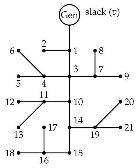
Figure 1.
The 21-node system.
4.2. The 69-Node System
Figure 2 shows the 69-node system, which is composed of 69 nodes and 68 lines. This test system originally operated in AC, but thanks to an adaptation made in [39], it is possible to use it for DC networks. For such adaptation, the active elements were disregarded, and a base voltage of 12.66 kV and a base power of 100 kW were considered. In this system, the slack generator injects a power of 4043.1 kW, and the power losses equal 153.855 kW. As in the 21-node system, all the DGs are allowed a penetration level of , , and of the power provided by the slack generator, with the minimum power being 0 kW for each DG and a maximum power of 808.6195, 1617.2390, and 2425.8585 kW for each penetration level. The location of the DGs was defined as in [39], i.e., they were located at nodes 26, 61, and 66. For this test system, a maximum current of 335 A was founded through the power flow evaluation, which corresponds to a 400-kcmil conductor located in a homogeneous or non-telescopic network. Additionally, the voltage limits for this system were set at +/− 10% of the nominal voltage.
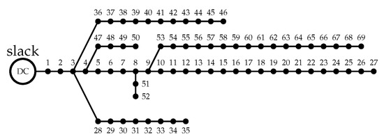
Figure 2.
The 69-node system.
5. Simulations and Results
This section analyzes the results obtained by the solution methods in the two test systems. All the simulations were performed in Matlab® (version ), a numerical computing system running on a laptop with 4 GB of RAM, an Intel® CoreTM i5-8250U @1.60GHz 1.80GHz processor, a 225 GB solid state drive, and Windows 10 PRO. All the methods were executed 100 times to evaluate the repeatability of the solutions and the standard deviation of each of the techniques. The following subsections present their results in the two test systems.
5.1. 21-Node System
Table 4 reports the results obtained by the methods implemented in this study to solve the OPF problem in the 21-node system at three penetration levels of distributed generation: , , and of the maximum power injected by the slack generator. From left to right, this table shows the solution method implemented, the nodes at which the DGs are located and the power injected by each of them (kW), the minimum power losses () in kW and the percentage of reduction compared to the base case (%), the average in kW and the average percentage of reduction with respect to the base case (%), the processing time required by the optimization algorithm to obtain the solution (s), the standard deviation (%), the worst voltage and the node at which it occurs, and the maximum current passing through the conducting lines.

Table 4.
Results of the simulations in the 21-node system.
Table 4 presents the solutions provided by each optimization technique to the OPF problem for the 21-node system. Using these values, Figure 3 and Figure 4 were constructed, which show the differences, in percentage, between the algorithms in terms of minimum and average reduction.
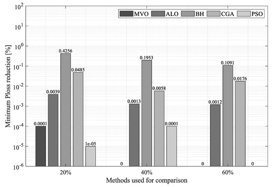
Figure 3.
Percentage of reduction in minimum power losses obtained by the SSA in the 21-node system compared to that of the other methodologies.
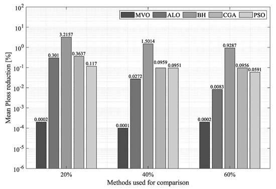
Figure 4.
Percentage of reduction in average power losses obtained by the SSA in the 21-node system compared to that of the other methodologies.
Figure 3 illustrates the minimum reduction obtained by each technique at the different penetration levels of distributed generation. In the scenario where of distributed power penetration was considered in relation to the power provided by the slack generator, both the SSA and the PSO reduced the minimum by . The MVO took third place in this regard, being outperformed in by the SSA and the PSO. The ALO, the CGA, and the BH are in fourth, fifth, and sixth position, respectively, with a reduction in minimum of , , and , respectively. At penetration, the SSA and the MVO exhibited the same reduction in minimum (), thus outperforming the PSO, the ALO, the CGA, and the BH by , , , and , respectively. Finally, at penetration, the SSA, the MVO, and the PSO achieved a reduction in minimum of , thus outperforming the ALO by , the CGA by , and the BH by .
Figure 4 details the average reduction obtained by each methodology at the different penetration levels of distributed generation. As observed in this figure, the SSA presented the highest average power loss reduction for the 21-node system. At penetration, the SSA achieved an average reduction of , thus outperforming the MVO, the PSO, the ALO, the CGA, and the BH by , , , , and , respectively. At penetration, the SSA presented an average reduction of , thus outperforming the MVO, the ALO, the PSO, the CGA, and the BH by , , , , and , respectively. Finally, at penetration, the SSA exhibited an average reduction of , thus outperforming the MVO by , the ALO by , the PSO by , the CGA by , and the BH by . This demonstrates the superiority of the SSA in finding a solution to the OPF problem in terms of average reduction in the 21-node system.
To analyze the repeatability of the proposed solution methodology, Figure 5 shows its reduction, in standard deviation, compared to that of the methods used for comparison. According to this figure, the proposed algorithm outperforms, in most cases, all the other techniques in terms of repeatability in the 21-node system. At penetration, both the SSA and the MVO obtained a standard deviation of , followed by the CGA, the PSO, the ALO, and the BH, which were outperformed by , , , and , respectively. At penetration, the SSA yielded a standard deviation of , thus outperforming the MVO by , the CGA by , the ALO by , the PSO by , and the BH by . Finally, at penetration, the SSA outperforms the MVO, the ALO, the CGA, the PSO, and the BH by , , , , and , respectively. These values demonstrate that, when executing multiple solutions in small networks, the proposed solution methodology is most likely to produce the best average response.
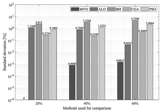
Figure 5.
Standard deviation obtained by the SSA in the 21-node system compared to that of the other methodologies.

Table 5.
Average minimum power losses vs. average processing time in the 21-node system.

Table 6.
Mean average power losses vs. average time in the 21-node system.
From left to right, Table 5 specifies the optimization method that was implemented; the average minimum obtained by each algorithm at all the penetration levels of distributed generation; the required average processing time; and the distance with respect to the origin (0,0), with the best solution to the problem being zero power losses at a required processing time of 0 s (Figure 6). The values reported in Table 5 are graphically represented in Figure 6, with the X-axis indicating the average minimum power losses obtained by each method; and the Y-axis, their required average processing time. As observed in this figure, the SSA (in blue) provides the best ratio of minimum reduction to processing time, and the MVO (in red) the worst ratio for the 21-node system. Therefore, the SSA is the most efficient method in terms of reduction in minimum power losses in small systems (in this case, the 21-node system).
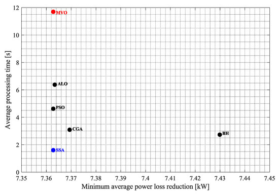
Figure 6.
Trade-off provided by the solution methodologies between average minimum power losses and required processing time in the 21-node system.
Table 6 shows the mean average power losses obtained by each technique when combining their impact on the three power injection levels allowed for the 21-node system, as well as their required processing times and distance to the origin (0,0). Figure 7 analyzes the ratio of average to processing time for each solution methodology.
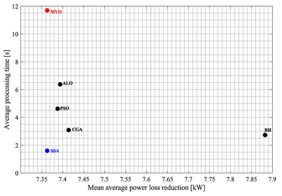
Figure 7.
Trade-off provided by the solution methodologies between mean average power losses and required processing time in the 21-node system.
From this figure, it can be seen that, as in the previous analysis, the proposed solution methodology presents the best ratio of average reduction to processing time, while the MVO continues to provide the worst solution. This may be explained by the fact that the proposed solution methodology not only has an excellent impact on solution quality but also requires shorter processing times, making it the most efficient method in terms of reduction in minimum and average power losses in small networks (such as the 21-node system).
5.2. The 69-Node System
Table 7 presents the results of the methods used in this study to solve the OPF problem in DC networks for the 69-node system. Using the information in this table, which was organized the same way as Table 4, Figure 8, Figure 9 and Figure 10 were constructed.

Table 7.
Results of the simulations of the 69-node system
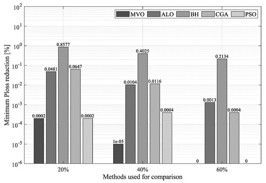
Figure 8.
Percentage of reduction in minimum power losses obtained by the SSA in the 69-node system compared to that of the other methodologies.
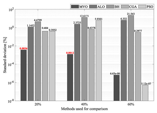
Figure 9.
Standard deviation obtained by the SSA in the 69-node system compared to that of the other methodologies.
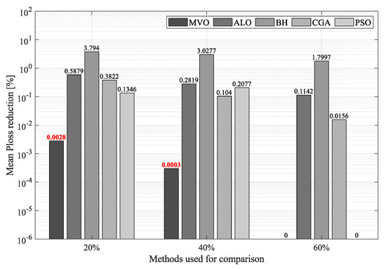
Figure 10.
Percentage of reduction in average power losses obtained by the SSA in the 69-node system compared to that of the other methodologies.
Figure 8 compares the percentages of reduction in minimum obtained by each solution methodology at the three allowable penetration levels. As observed in this figure, at penetration, the SSA reported a minimum reduction of , thus outperforming the MVO and the PSO by , the ALO by , the CGA by , and the BH by . At penetration, the SSA and the MVO presented a minimum reduction of ; followed by the PSO, which takes the third position with a reduction of ; the ALO, with a reduction of ; and, finally, the CGA and the BH, with a reduction of and , respectively. At penetration, the SSA, the MVO, and the PSO achieved a minimum reduction of , followed by the CGA, the ALO, and the BH, with a reduction of , , and , respectively.
Figure 9 compares the solutions obtained by the algorithms employed here in terms of average reduction. At penetration, the MVO reported the highest percentage of reduction in average (), thus outperforming the SSA by , which was followed by the PSO, the CGA, the ALO, and the BH, with a reduction of , , , and , respectively. At penetration, the MVO is again the technique with the highest percentage of reduction (), thus outperforming the SSA by only , which was followed by the CGA (in third place), the PSO (in fourth place), the ALO (in fifth place), and the BH (in sixth place), with a reduction of , , , and , respectively. At penetration, the SSA, the MVO, and the PSO achieved a reduction of , followed by the CGA, the ALO, and the BH, with an average reduction of , , and , respectively.
To complete the analysis of the 69-node system, Figure 10 compares the standard deviation obtained by each optimization technique when solving the OPF problem in DC networks. From this figure, it can be seen that although the proposed solution methodology is outperformed by the MVO by only at penetration, it outperforms the PSO by , the CGA by , and the BH by . At penetration, the MVO is again the technique with the best standard deviation, thus outperforming the SSA by ; however, the SSA outperforms all the other methodologies by on average. At penetration, the SSA presented the best standard deviation (), thus outperforming the PSO and the MVO by only and , respectively. Likewise, the SSA outperforms the CGA by , the ALO by , and the BH by .
Finally, in order to establish which optimization technique presents the best ratio of solution quality to processing time, Table 8 and Table 9 report the average results obtained by each methodology in terms of minimum and average power losses at the three penetration levels of distributed generation for the 69-node system.

Table 8.
Average minimum power losses vs. average time in the 69-node system.

Table 9.
Mean average power losses vs. average time in the 69-node system.
Table 8 is organized the same way as Table 5, but it contains information for the 69-node system. In this table, the minimum obtained by each optimization technique at the three penetration levels of distributed generation and their required processing times were averaged. Subsequently, using the data contained in Table 8, Figure 11 was constructed. In this figure, as in Figure 6, the X-axis indicates the average minimum power losses, and the Y-axis, the average time required by each technique to converge to the solution. As observed in Figure 11, the technique with the best ratio of minimum power losses to average processing time is the SSA (in blue) and that with the worst ratio is the MVO (in red). Thus, the SSA is the most efficient algorithm in terms of reduction in minimum power losses at any penetration level in large DC networks (in this case, the 69-node system).
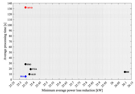
Figure 11.
Trade-off provided by the solution methodologies between average minimum power losses and required processing time in the 69-node system.
Table 9 presents the average time that each technique takes to converge to the solution (Y-axis in Figure 12), the mean of the average obtained by each algorithm (X-axis in Figure 12), and the distance between the origin (0,0) and the point of each technique in Figure 12.
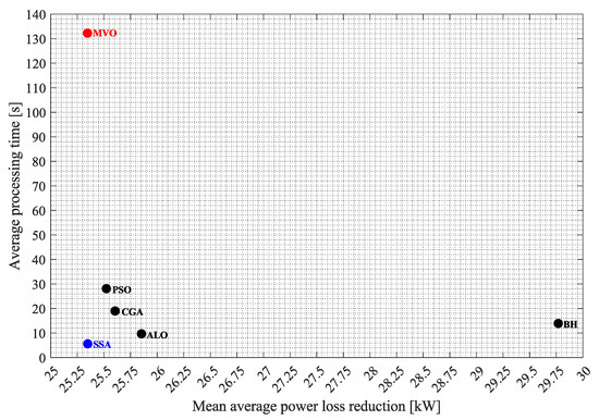
Figure 12.
Trade-off provided by the solution methodologies between mean average power losses and required processing time in the 69-node system.
As observed in Figure 12, the SSA is the technique that is closest to the origin, i.e., it exhibits the best ratio of average to average processing time, while the MVO is the technique that is farthest from the origin, i.e., it presents the worst ratio of average to average processing time. From Figure 11 and Figure 12, it can be concluded that the SSA is the algorithm that provides the best solution in terms of minimum and average at the shortest processing time for large networks.
6. Conclusions
This paper proposed the implementation of a new optimization technique (SSA) to solve the OPF problem in DC networks using a master–slave methodology. In the master stage, the SSA determines the power to be injected by each DG located in the DC network. In the slave stage, the SA method estimates the impact of each solution proposed by the master stage on the objective function and the constraints of the OPF problem. In order to demonstrate the effectiveness and robustness of the proposed solution methodology, it was compared with five other optimization techniques that have been reported in the specialized literature to solve the OPF problem in DC networks: MVO, ALO, BH, CGA, and PSO. Each method was validated in two test systems (the 21- and 60-node systems) at three penetration levels of distributed generation: , , and of the power provided by the slack node. Each test scenario was executed 100 times in order to evaluate the repeatability of the solutions obtained.
Based on the results of the test scenarios proposed in this study, the SSA proved to deliver the best average solution in terms of reduction in minimum and average power losses at an adequate processing time. Additionally, when comparing the ratios of minimum and average power loss reduction to processing time of each technique used here, the proposed methodology yielded the best ratio for DC networks of any size. In other words, the SSA manages to have a better impact on power losses, through power injection by the DGs, at a shorter processing time. Since algorithms are required to find a solution to each power generation and demand variation occurring in the network, the computation time necessary to solve the OPF problem is critical. Energy management systems must react before the power generation and demand conditions change again. Additionally, processing times can be used to broaden the search and improve the response, which is useful in scenarios with large solution systems. According to the results of this study, the proposed solution technique achieves the best ratio of solution quality to processing time, which is ideal in energy management or planning strategies. Importantly, convex optimization solvers produce high-quality solutions at short processing times but demand using specialized software, which increases costs and forces to acquire specialized computer equipment for its execution. This goes against the purpose of this paper, which is to achieve high-quality solutions at short processing times while eliminating the need for specialized software and related costs.
Regarding the repeatability of the solutions obtained, the proposed solution methodology exhibited low standard deviations (with values around %) and outperformed most of the other techniques in the different test systems and scenarios considered here, thus demonstrating the reproducibility and achievability of its solution every time the algorithm is executed. At the user level, this ensures that every time this technique is used to solve the OPF problem, its solutions will almost always be the best that the algorithm can produce.
For all the reasons mentioned above and after comparing the proposed solution methodology with the most efficient methods reported in the specialized literature thus far, it can be concluded that the SSA is the best technique to solve the OPF problem in DC networks of any size when it comes to reducing power losses and when considering the set of constraints of DC networks in an environment of distributed generation.
Future studies could consider using, as the objective function, the reduction in the operating costs of DC networks in a scenario of distributed generation. In addition, they could include an environmental impact assessment, considering the integration of distributed generation based on fossil fuels. It would also be interesting to analyze the power generation and demand curves in a multi-hourly optimal power dispatch setting. Moreover, further research should explore the integration of energy storage elements (e.g., batteries), which were not covered in this paper. Finally, future studies might implement the SSA–SA methodology to solve the OPF problem in AC networks. For this purpose, they should adequately analyze its impact on solution quality and required processing times to determine its impact on electrical networks in general.
Author Contributions
Conceptualization, A.A.R.M., L.F.G.-N., J.M., O.D.M. and D.A.G.-R.; methodology, A.A.R.M., L.F.G.-N., J.M., O.D.M. and D.A.G.-R.; formal analysis, A.A.R.M., L.F.G.-N., J.M., O.D.M. and D.A.G.-R.; investigation, A.A.R.M., L.F.G.-N., J.M., O.D.M. and D.A.G.-R.; resources, A.A.R.M., L.F.G.-N., J.M., O.D.M. and D.A.G.-R.; writing—original draft preparation, A.A.R.M., L.F.G.-N., J.M., O.D.M. and D.A.G.-R. All authors have read and agreed to the published version of the manuscript.
Funding
This research was funded by the program of "Jovenes investigadores" del Instituto Tecnológico Metropolitano de Medellín.
Data Availability Statement
No new data were created or analyzed in this study. Data sharing is not applicable to this article.
Acknowledgments
This work was supported in part by the Centro de Investigación y Desarrollo Científico de la Universidad Distrital Francisco José de Caldas under grant 1643-12-2020 associated with the project: “Desarrollo de una metodología de optimización para la gestión óptima de recursos energéticos distribuidos en redes de distribución de energía eléctrica.”
Conflicts of Interest
The authors declare no conflict of interest.
References
- Gurven, M.; Walker, R. Energetic demand of multiple dependents and the evolution of slow human growth. Proc. R. Soc. B Biol. Sci. 2006, 273, 835–841. [Google Scholar] [CrossRef] [Green Version]
- Gupta, B.R. Generation of Electrical Energy; S. Chand Publishing: New Delhi, India, 2017; pp. 1–616. Available online: https://books.google.com.co/books?hl=es&lr=&id=bERxDwAAQBAJ&oi=fnd&pg=PR1&dq=Generation+of+Electrical+Energy&ots=vxlWpcSTf5&sig=vzzX7SReWRerVqawXEXGe77LQlE&redir_esc=y#v=onepage&q=Generation%20of%20Electrical%20Energy&f=false (accessed on 16 November 2021).
- Kyriakopoulos, G.L.; Arabatzis, G. Electrical energy storage systems in electricity generation: Energy policies, innovative technologies, and regulatory regimes. Renew. Sustain. Energy Rev. 2016, 56, 1044–1067. [Google Scholar] [CrossRef]
- Krauter, S. Solar Electric Power Generation; Springer: Berlin/Heidelberg, Germany, 2006; Volume 10, pp. 978–983. [Google Scholar]
- Grigsby, L.L. Electric Power Generation, Transmission, and Distribution; CRC Press: Boca Raton, FL, USA, 2007. [Google Scholar] [CrossRef]
- Christensen, L.R.; Greene, W.H. Economies of scale in US electric power generation. J. Political Econ. 1976, 84, 655–676. [Google Scholar] [CrossRef]
- Grisales-Noreña, L.F.; Montoya, O.D.; Hincapié-Isaza, R.A.; Echeverri, M.G.; Perea-Moreno, A.J. Optimal Location and Sizing of DGs in DC Networks Using a Hybrid Methodology Based on the PPBIL Algorithm and the VSA. Mathematics 2021, 9, 1913. [Google Scholar] [CrossRef]
- Sánchez, L.G.G. Localización óptima de generación Distribuida en Sistemas de Distribución Trifásicos con Carga Variable en el Tiempo Utilizando el método de Monte Carlo. Ph.D. Thesis, Universitat Politècnica de Catalunya, Barcelona, Spain, 2012. [Google Scholar]
- Bove, R.; Lunghi, P. Electric power generation from landfill gas using traditional and innovative technologies technologies. Energy Convers. Manag. 2006, 47, 1391–1401. [Google Scholar] [CrossRef]
- Gollop, F.M.; Roberts, M.J. Environmental Regulations and Productivity Growth: The Case of Fossil-fueled Electric Power Generation. Economy 1983, 91, 654–674. [Google Scholar] [CrossRef]
- Koohi-Fayegh, S.; Rosen, M.A. A review of energy storage types, applications and recent developments. J. Energy Storage 2020, 27, 101047. [Google Scholar] [CrossRef]
- Pan, H.; Hu, Y.; Chena, L. Room-temperature stationary sodium-ion batteries for large-scale electric energy storage. Energy Environ. Sci. 2013, 6, 2338. [Google Scholar] [CrossRef]
- Joseph, A.; Shahidehpour, M. Battery Storage Systems in Electrical Power Systems Power Systems. J. Energy Storage 2017, 12, 87–107. [Google Scholar] [CrossRef]
- Peters, J.F.; Baumann, M.; Zimmermann, B.; Braun, J.; Weil, M. The environmental impact of Li-Ion batteries and the role of key parameters—A review Renew. Sustain. Energy Rev. 2017, 67, 491–506. [Google Scholar] [CrossRef]
- Kumar, J.; Agarwal, A.; Agarwal, V. A review on overall control of DC microgrids. J. Energy Storage 2019, 21, 113–138. [Google Scholar] [CrossRef]
- Grisales-Noreña, L.F.; Ramos-Paja, C.A.; Gonzalez-Montoya, D.; Alcalá, G.; Hernandez-Escobedo, Q. Energy management in PV based microgrids designed for the Universidad Nacional de Colombia. Sustainability 2020, 12, 1219. [Google Scholar] [CrossRef] [Green Version]
- Franck, C.M. HVDC circuit breakers: A review identifying future research needs. IEEE Trans. Power Deliv. 2011, 26, 998–1007. [Google Scholar] [CrossRef] [Green Version]
- Momoh, J.; Koessler, R.; Bond, M.; Stott, B.; Sun, D.; Papalexopoulos, A.; Ristanovic, P. Challenges to optimal power flow. IEEE Trans. Power Syst. 1997, 12, 444–455. [Google Scholar] [CrossRef] [Green Version]
- Ocampo-Toro, J.; Garzon-Rivera, O.; Grisales-Noreña, L.; Montoya-Giraldo, O.; Gil-González, W. Optimal Power Dispatch in Direct Current Networks to Reduce Energy Production Costs and CO2 Emissions Using the Antlion Optimization Algorithm. Arab. J. Sci. Eng. 2021, 46, 9995–10006. [Google Scholar] [CrossRef]
- Grisales-Noreña, L.F.; Garzón Rivera, O.D.; Ocampo Toro, J.A.; Ramos-Paja, C.A.; Rodriguez Cabal, M.A. Metaheuristic Optimization Methods for Optimal Power Flow Analysis in DC Distribution Networks Trans. Energy Syst. Eng. Appl. 2020, 1, 13–31. [Google Scholar] [CrossRef]
- Montoya, O.D.; Grisales-Noreña, L.; González-Montoya, D.; Ramos-Paja, C.; Garces, A. Linear power flow formulation for low-voltage DC power grids. Electr. Power Syst. Res. 2018, 163, 375–381. [Google Scholar] [CrossRef]
- Gavrilas, M. Heuristic and Metaheuristic Optimization Techniques with Application to Power Systems; Technical University of Iasi, D. Mangeron Blvd.: Iasi, Romania, 2010. [Google Scholar]
- Orosz, T.; Rassõlkin, A.; Kallaste, A.; Arsénio, P.; Pánek, D.; Kaska, J.; Karban, P. Robust design optimization and emerging technologies for electrical machines: Challenges and open problems. Appl. Sci. 2020, 10, 6653. [Google Scholar] [CrossRef]
- Li, J.; Liu, F.; Wang, Z.; Low, S.H.; Mei, S. Optimal power flow in stand-alone DC microgrids. IEEE Trans. Power Syst. 2018, 33, 5496–5506. [Google Scholar] [CrossRef] [Green Version]
- Montoya, O.; Gil-González, W.; Grisales-Noreña, L. Optimal Power Dispatch of DGs in DC Power Grids: A Hybrid Gauss-Seidel-Genetic-Algorithm Methodology for Solving the OPF Problem. Wseas Trans. Power Syst. 2018, 13, 335–346. [Google Scholar]
- Montoya, O.D.; Gil-González, W.; Garces, A. Sequential quadratic programming models for solving the OPF problem in DC grids. Electr. Power Syst. Res. 2019, 169, 18–23. [Google Scholar] [CrossRef]
- Garzon-Rivera, O.; Ocampo, J.; Grisales-Noreña, L.; Montoya, O.; Rojas-Montano, J. Optimal power flow in Direct Current Networks using the antlion optimizer. Stat. Optim. Inf. Comput. 2020, 8, 846–857. [Google Scholar] [CrossRef]
- Montoya, O.D.; Grisales-Noreña, L.F.; Amin, W.T.; Rojas, L.A.; Campillo, J. Vortex Search Algorithm for Optimal Sizing of Distributed Generators in AC Distribution Networks with Radial Topology. In Workshop on Engineering Applications; Springer: Berlin/Heidelberg, Germany, 2019; pp. 235–249. [Google Scholar]
- Velasquez, O.S.; Montoya Giraldo, O.D.; Garrido Arevalo, V.M.; Grisales Norena, L.F. Optimal power flow in direct-current power grids via black hole optimization. Adv. Electr. Electron. Eng. 2019, 17, 24–32. [Google Scholar] [CrossRef]
- Mirjalili, S.; Gandomi, A.H.; Mirjalili, S.Z.; Saremi, S.; Faris, H.; Mirjalili, S.M. Salp Swarm Algorithm: A bio-inspired optimizer for engineering design problems. Adv. Eng. Softw. 2017, 114, 163–191. [Google Scholar] [CrossRef]
- Montoya, O.D.; Garrido, V.M.; Gil-González, W.; Grisales-Noreña, L.F. Power flow analysis in DC grids: Two alternative numerical methods. IEEE Trans. Circuits Syst. II Express Briefs 2019, 66, 1865–1869. [Google Scholar] [CrossRef]
- Abualigah, L.; Shehab, M.; Alshinwan, M.; Alabool, H. Salp swarm algorithm: A comprehensive survey. Neural Comput. Appl. 2020, 32, 11195–11215. [Google Scholar] [CrossRef]
- Kennedy, J.; Eberhart, R. Particle swarm optimization. In Proceedings of the ICNN’95-international conference on neural networks, Perth, Australia, 27 November–1 December 1995; Volume 4, pp. 1942–1948. [Google Scholar]
- Hatamlou, A. Black hole: A new heuristic optimization approach for data clustering. Inf. Sci. 2013, 222, 175–184. [Google Scholar] [CrossRef]
- Chelouah, R.; Siarry, P. A continuous genetic algorithm designed for the global optimization of multimodal functions. J. Heuristics 2000, 6, 191–213. [Google Scholar] [CrossRef]
- Zawbaa, H.M.; Emary, E.; Parv, B. Feature selection based on antlion optimization algorithm. In Proceedings of the 2015 Third World Conference on Complex Systems (WCCS), Marrakech, Morocco, 23–25 November 2015; pp. 1–7. [Google Scholar]
- Mirjalili, S.; Jangir, P.; Mirjalili, S.Z.; Saremi, S.; Trivedi, I.N. Optimization of problems with multiple objectives using the multi-verse optimization algorithm. Knowl.-Based Syst. 2017, 134, 50–71. [Google Scholar] [CrossRef] [Green Version]
- Gil-González, W.; Montoya, O.D.; Holguín, E.; Garces, A.; Grisales-Noreña, L.F. Economic dispatch of energy storage systems in dc microgrids employing a semidefinite programming model. J. Energy Storage 2019, 21, 1–8. [Google Scholar] [CrossRef]
- Grisales-Noreña, L.F.; Gonzalez Montoya, D.; Ramos-Paja, C.A. Optimal sizing and location of distributed generators based on PBIL and PSO techniques. Energies 2018, 11, 1018. [Google Scholar] [CrossRef] [Green Version]
- Garcés, A. On the convergence of Newton’s method in power flow studies for DC microgrids. IEEE Trans. Power Syst. 2018, 33, 5770–5777. [Google Scholar] [CrossRef] [Green Version]
- Rosales-Muñoz, A.A.; Grisales-Noreña, L.F.; Montano, J.; Montoya, O.D.; Perea-Moreno, A.J. Application of the Multiverse Optimization Method to Solve the Optimal Power Flow Problem in Direct Current Electrical Networks. Sustainability 2021, 13, 8703. [Google Scholar] [CrossRef]
Publisher’s Note: MDPI stays neutral with regard to jurisdictional claims in published maps and institutional affiliations. |
© 2021 by the authors. Licensee MDPI, Basel, Switzerland. This article is an open access article distributed under the terms and conditions of the Creative Commons Attribution (CC BY) license (https://creativecommons.org/licenses/by/4.0/).