Article

An Imaging Enhancement Method for a Terahertz Rotation Mirror Imaging System Based on a Scale-Recurrent Network

1
Wuhan National Laboratory for Optoelectronics, School of Optical and Electronic Information, Huazhong University of Science and Technology, Wuhan 430074, China
2
AVIC Beijing Changcheng Aeronautical Measurement and Control Technology Research Institute, Beijing 101111, China
*
Author to whom correspondence should be addressed.
Electronics 2021, 10(22), 2821; https://doi.org/10.3390/electronics10222821
Submission received: 19 October 2021 / Revised: 11 November 2021 / Accepted: 15 November 2021 / Published: 17 November 2021
(This article belongs to the Section Microwave and Wireless Communications)

Abstract

:
The terahertz (THz) rotation mirror imaging system is an alternative to the THz array imaging system. A THz rotation mirror imaging system costs less than a THz array imaging system, while the imaging speed of a THz rotation mirror imaging system is much higher than the imaging speed of a THz raster-scan imaging system under the same hardware conditions. However, there is some distortion in the THz image from the THz rotation mirror imaging system. The distortion, which makes images from the THz rotation mirror imaging system difficult to identify, results from the imaging principle of the THz rotation mirror imaging system. In this article, a method based on the scale-recurrent network (SRN) is put in place to correct the distortion. A comparison between distorted THz images and corrected images shows that the proposed method significantly increases the structural similarity between the THz images and the samples.

1. Introduction

THz waves are electromagnetic waves ranging from 0.1 THz to 10 THz [1]. THz waves are nonionizing [2] and have the ability to penetrate foam [3], ceramic [4], and magnetic material [5] as well as polymer composites [6]. Therefore, the THz imaging technique has great application prospects for non-contact [7,8] and non-destructive [9,10] detection. In addition, the use of terahertz radiation has a very promising future in medical imaging due to its nonionizing properties [11].
In the last 20 years, research on THz imaging has been conducted on a large scale [12,13]. There are two types of THz imaging techniques. One is called the THz active imaging technique, which includes THz computed tomography (CT) [14], THz synthetic aperture radar (SAR) [15], terahertz frequency-modulated continuous wave (FMCW) radar [16], THz time-domain spectroscopy (TDS) [17] and THz scanning near-field microscopy (SNOM) [18], etc. The other is the THz passive imaging technique [19,20,21,22].
For the THz active imaging technique, the THz pixel-by-pixel scanning imaging method is the most frequently used imaging method because THz array components are expensive. The THz raster-scan imaging system is the most common THz pixel-by-pixel scanning imaging method. However, the THz raster-scan imaging method has always been criticized for its slow imaging speed. The application of the THz raster-scan imaging method is limited in some fields because of the THz raster-scan imaging method’s slow imaging speed; for example, in the field of THz biomedical imaging, it is hard to keep a creature at rest for a long time. The imaging process must be completed in a short time. Therefore, the THz array imaging system, which is expensive, is most widely used in the field of THz biomedical imaging [23,24].
The THz rotation mirror imaging system, first suggested by C. A. Weg et al. in 2009 [25], is a kind of THz pixel-by-pixel scanning imaging system. This system is offered as an alternative to the THz array imaging system [26]. A THz rotation mirror imaging system costs less than one tenth of a THz array imaging system. Additionally, the imaging speed of a THz rotation mirror imaging system is much higher than the imaging speed of a THz raster-scan imaging system under the same hardware conditions.
Though the THz rotation mirror imaging system has many advantages, there is one major drawback: distortion exists in the THz image from the THz rotation mirror imaging system. Depending on the imaging principle of the THz rotation mirror imaging system, the THz image is reconstructed by a series of triangles [27]. Therefore, the THz image from the THz rotation mirror imaging system consists of a series of triangles instead of squares. That is the main reason for the distortion of the THz image.
Many studies on distortion correction have been reported. Some of them focus on the distortion correction of diffusion magnetic resonance imaging (DMRI) [28], some of them focus on the distortion correction of radial lenses [29], some of them focus on the distortion correction of cameras [30], some of them focus on the distortion correction of scanning electron microscopy imaging [31], etc. However, few of them pay attention to the distortion correction of the THz rotation mirror imaging system.
The distortion correction of the THz rotation mirror imaging system can hardly be resolved by traditional methods because the distortion correction is an ill-posed problem. In this article, a method based on the scale-recurrent network (SRN) is introduced to correct the distortion of the THz rotation mirror imaging system, considering that the basic outlines of the sample in the THz image are unchanged. SRN, proposed by X. Tao et al. in 2018 [32], has the ability to learn image features in a coarse-to-fine way.
In this paper, a training set is built. The training set allows the proposed network to be trained well so that the distortion of the THz rotation mirror imaging system can be effectively corrected by the network.
According to the quantitative results, the method proposed in this article has the ability to increase the THz image quality effectively.

2. Theory

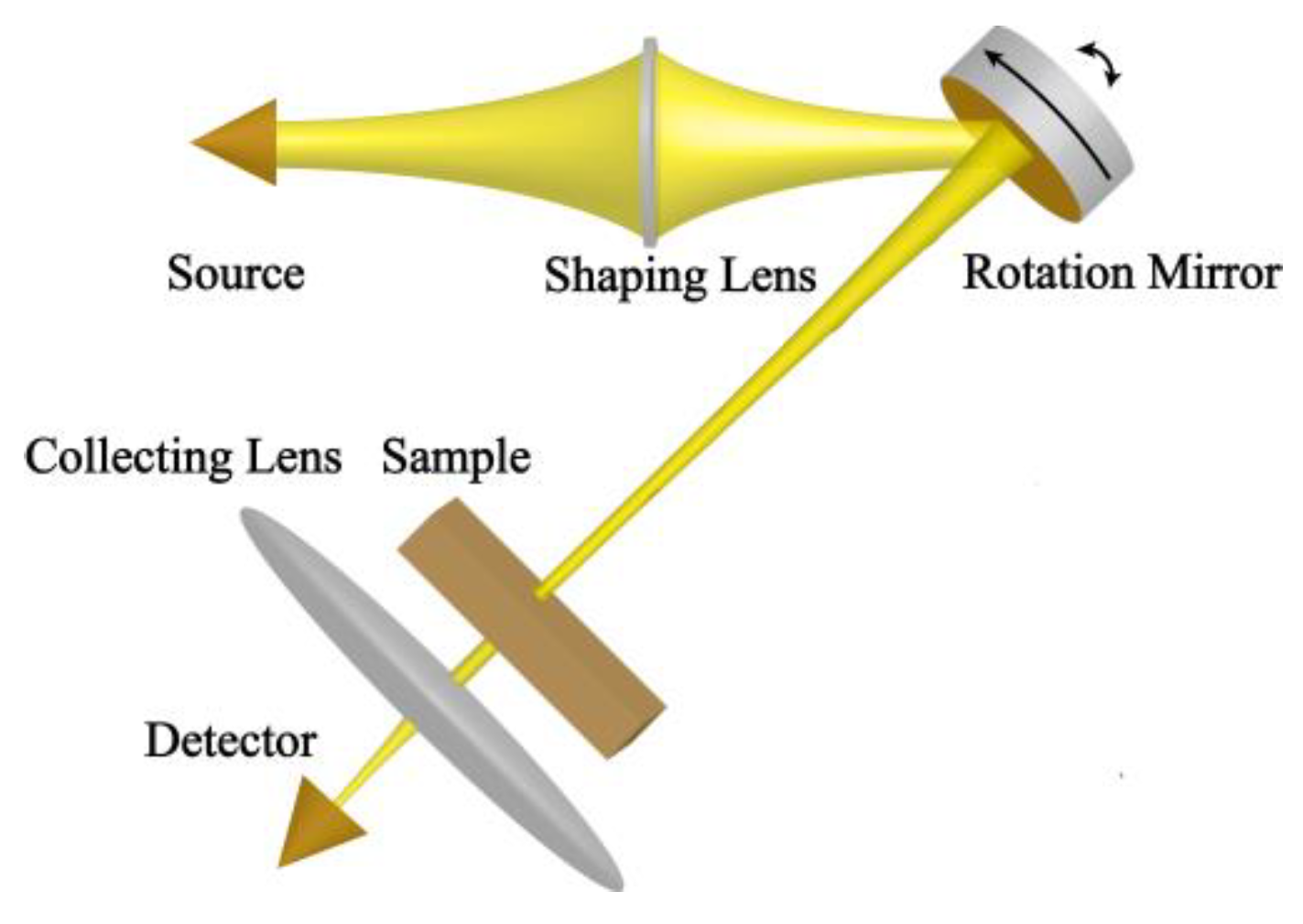
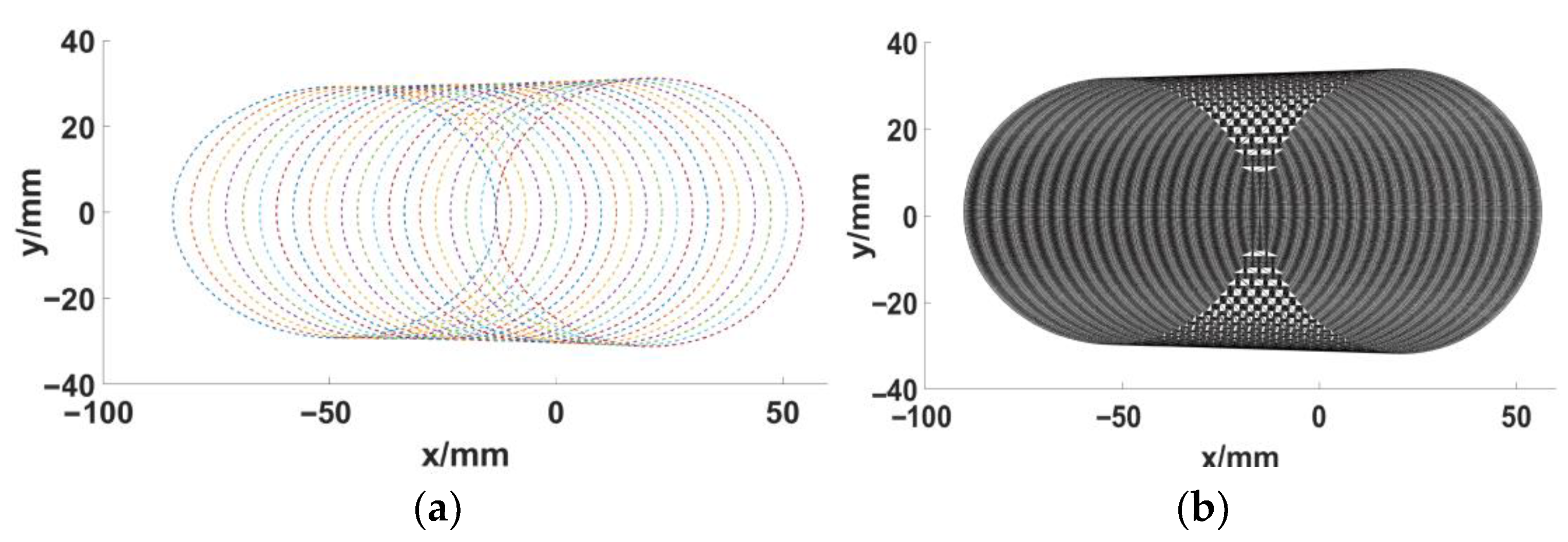
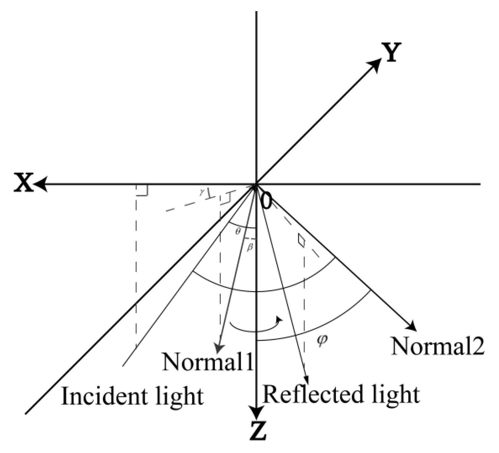
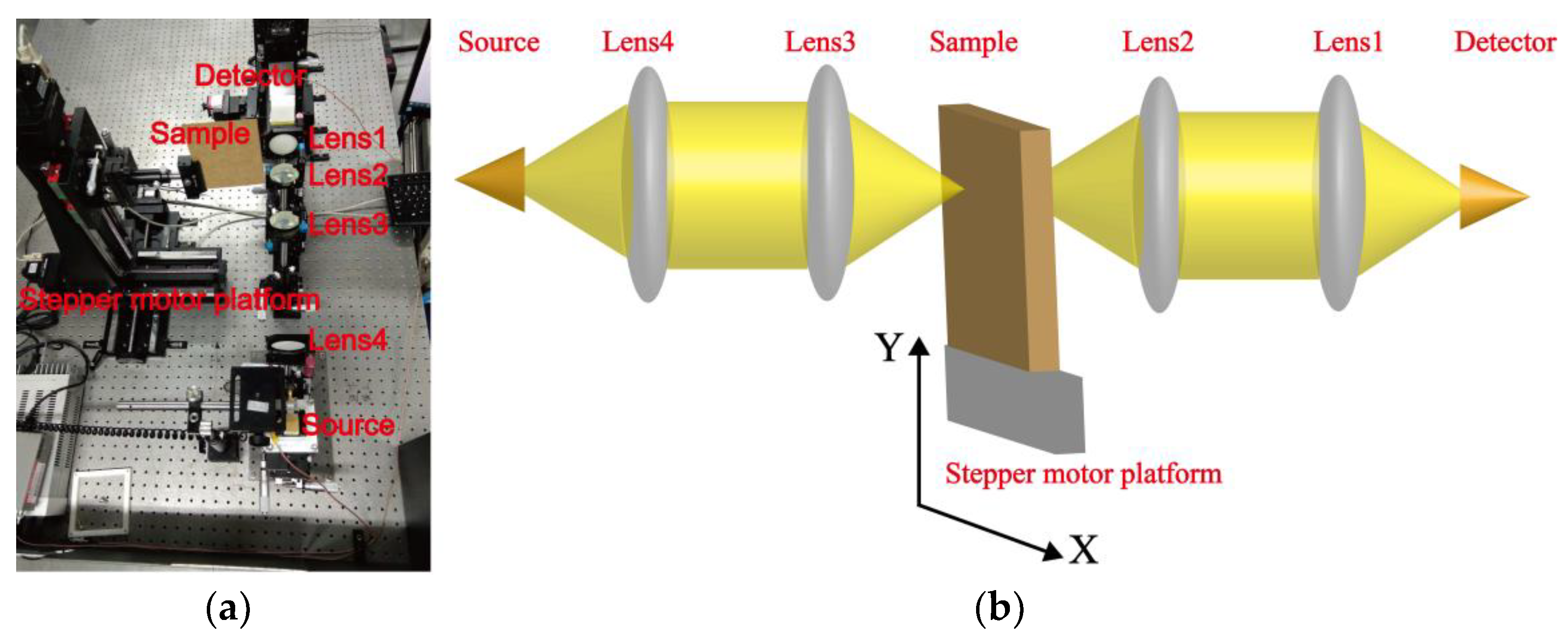
2.1. Imaging Principle of THz Rotation Mirror Imaging System

A schematic diagram of the THz rotation mirror imaging system is shown in Figure 1. According to Figure 1, passing through the shaping lens, the THz wave from the source then hits the rotation mirror. The rotation mirror deflects the converging wave and thus directs it to the sample. Penetrating through the sample, the THz wave is then focused on the detector by the collecting lens. The scanning is achieved by the rotation mirror rotating about two perpendicular axes. The rotation mirror is installed on a spinning axis. The tilt at an angle causes an ellipse-shaped scanning path of the focal spot in the object plane. A rotary stage turns the first axis in a direction perpendicular to it, thereby leading to a linear movement of the scanning ellipse. Figure 2a shows the scan path—i.e., the scan points from which the imaging data are received. The triangulation of the scan points based on the Delaunay algorithm [33] is presented in Figure 2b. The image can be obtained by filling every triangle with the average pixel value of its three vertexes.

2.2. Network Structure

The proposed network is expressed as:
O u t p u t = N e t E - D ( I n p u t , N e t E - D ( I n p u t , N e t E - D ( I n p u t , I n p u t , h 1 ; θ 1 ) , h 2 ; θ 2 ) , h 3 ; θ 3 )
where NetE-D is an Encoder-Decoder block with the training parameter θ, h is the hidden state feature of the Encoder-Decoder block, Input is the THz image, Output is the output of the network, is a downsampling operator mand is an upsampling operator. On the proposed scale-recurrent network, image restoration is carried out in a coarse-to-fine manner.
The proposed network structure is illustrated in Figure 3. As shown in Figure 3a, the overall structure is a scale-recurrent structure. The downsampling operation will halve the image size while the upsampling operation, realized by way of bilinear interpolation, will double the image size. The structure of the Encoder-Decoder block is shown in Figure 3b. The Encoder-Decoder Residual block contains an Input Residual block, two Encoder Residual blocks, two Decoder Residual blocks, and an Output Residual block. There are 64 filters and 128 filters in the two Encoder Residual blocks (Eblock) and there are 128 filters and 64 filters in the two Decoder Residual blocks (Dblock). The Eblock includes a convolution layer (Conv), and three Residual blocks. The stride for the convolution layer is two. It doubles the number of kernels of the previous layer. There are two convolution layers in a Residual block (Resblock). The Dblock contains three Residual blocks and one deconvolution layer (Deconv). The deconvolution layer will halve the number of kernels. The Input Residual block (Iblock), which produces a 32-channel feature map, contains three Residual blocks and one deconvolution layer. The Output Residual block (Oblock), which generates the output image, contains three Residual blocks and a convolution layer. In the network proposed in this article, the convolution kernels are 3 × 3 for every convolution layer.
The mean squared error (MSE) is adopted as the loss function of the proposed model. The loss function can be expressed as:
L M S E ( θ ) = 1 3 N k = 1 3 i = 1 N I p r e d i c t ( I i n , θ ) I s tan d a r d
where LMSE denotes the MSE between the standard images and the predicted images, N denotes the number of training samples, θ denotes the weight of the network, Ipredict is the output of the network, and Istandard is the standard image.

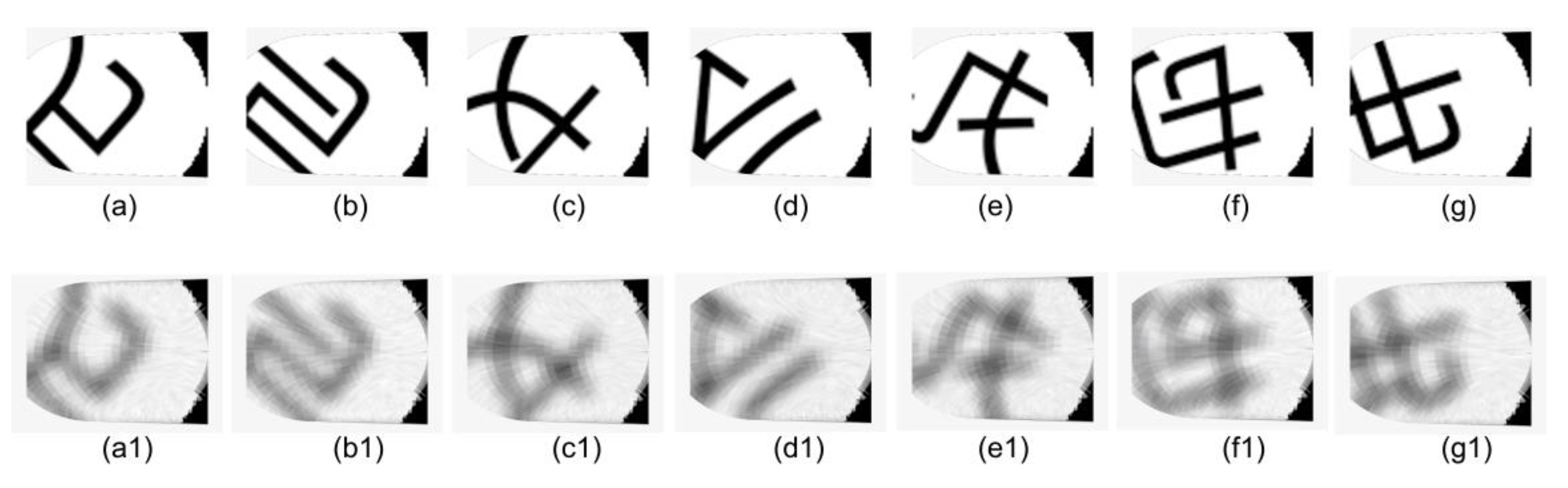
2.3. Training Set Creation

In Figure 4, the Z axis is the first spinning axis of the THz rotation mirror system. Normal1 is normal to the rotation mirror plane. Point O is the incident point of the incident light on the rotation mirror plane. The path of incidence is in the XZ plane. Normal2 is normal to the object plane. In spherical coordinates, let the unit vector of incident light be (1, θ, 0), the unit vector of Normal1 be (1, β, γ), the unit vector of Normal2 be (1, φ, 180°), and the distance between the point O and the object plane be d. Then in a Cartesian coordinate system of (1, 90°−φ, 0), axis Y and Normal2, the scanning spot (x’, y’) on the object plane is the point at which the vector (x’, y’, d) intersects the object plane and can be expressed as:
{ x = d ( κ 1 cos φ + κ 2 sin φ ) κ 2 cos φ κ 1 sin φ y = d ( κ 2 + cos θ ) tan β sin γ κ 2 cos φ κ 1 sin φ
where 𝜅1, 𝜅2 can be calculated as:
{ κ 1 = tan β cos γ ( c + cos θ ) sin θ κ 2 = cos β [ 2 ( sin β cos γ sin θ + cos β cos θ ) 2 1 ] + cos β sin 2 θ sin β cos γ sin θ cos θ sin β cos γ + cos β sin θ
In this paper, the θ is from 22° to 32° at 0.5° intervals, the γ is from 0° to 359.5° at 0.5° intervals, β is 5° and the φ = 50°−θ. Thus, the scanning spots on the sampled image can be determined.
Considering the image degradation, the sampled image can be obtained from the following equation:
I s a m p l e d = ( I s tan d a r d P S F ) + n
where Isampled is the sampled image, Istandard the standard image, PSF is the Gaussian point spread function (GPSF), n is the additive white Gaussian noise (AWGN), and ⨂ is the convolution operation. Because the radius of the spot on the object plane is about 6 mm, a 13 × 13 matrix is selected as the Gaussian point spread function PSF. Elements in the PSF can be calculated as:
P S F = 1 2 π · 6 2 exp ( ( x 2 + y 2 ) 2 · 6 2 )
Acquiring all the scanning points on the sampled image, the simulation THz image can be reconstructed using the Delaunay algorithm.

3. Experimental Setup and Implementation Details

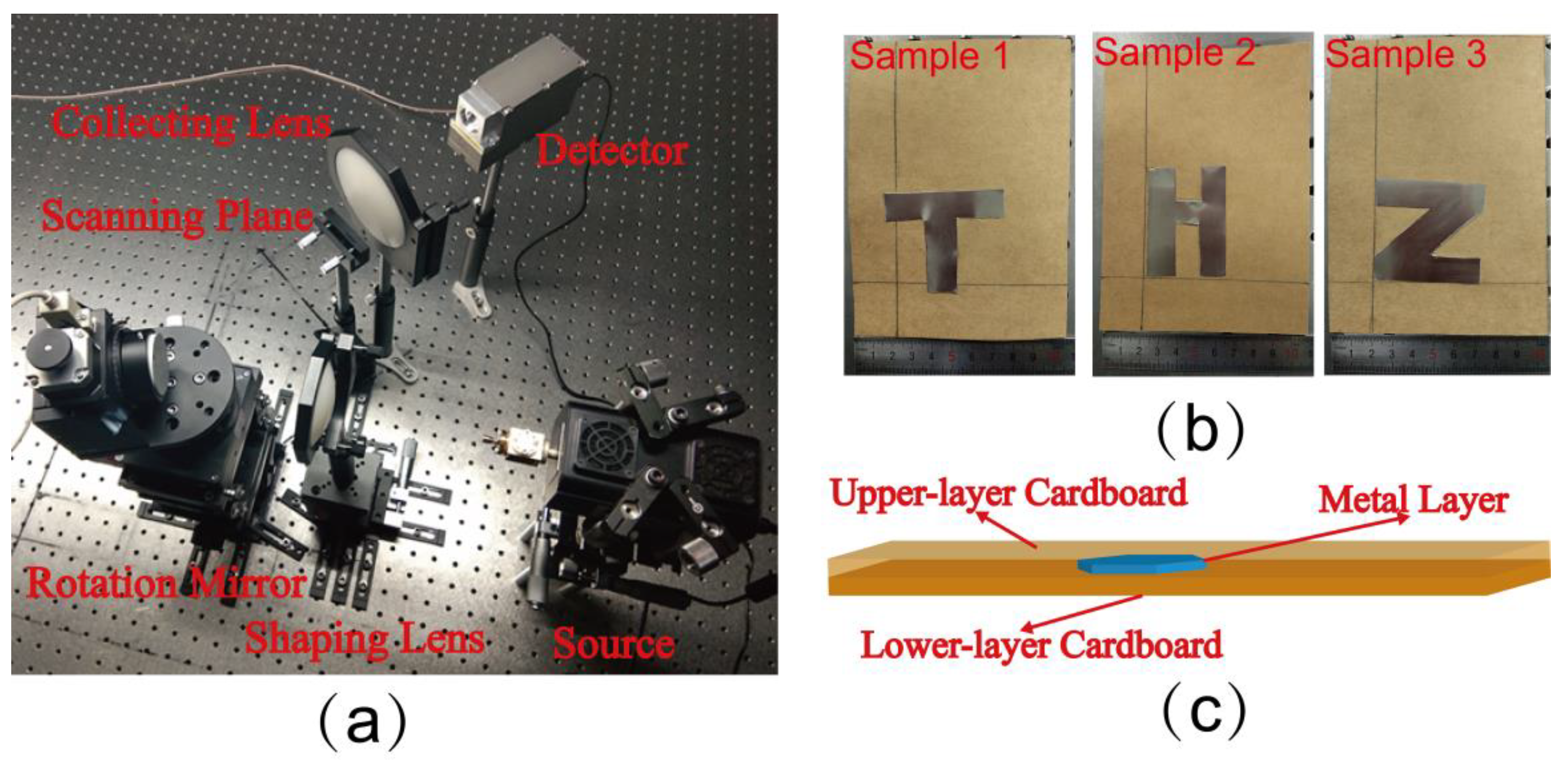
3.1. THz Rotation Mirror Imaging Experiment

A THz rotation mirror imaging system was built to carry out the imaging experiment. Figure 1 shows the schematic diagram of the experimental setup. A photograph of the THz rotation mirror imaging system is presented in Figure 5a. The source, produced by TeraSense, is a THz impact ionization avalanche transit-time (IMPATT) diode. The radiated power of the source is 2 milliwatts (mW) and the center frequency of the transmitted THz wave is 0.3 THz. The detector with a frequency response range from 0.1 to 1.15 THz is a high electron mobility field–effect transistor (FET). The shaping lens is a 2 inch convex lens and its focal length is 75 mm. The collecting lens is a 4 inch convex lens and its focal length is 100 mm. The reflecting surface of the rotation mirror is tilted at an angle of 5° against the rotation mirror’s fast rotation axis.
Three samples with metal layers in the shapes of three different letters were designed for the imaging experiment. The metal layers of the three samples are shown in Figure 5b and the common structure of them is shown in Figure 5c. As can be seen in Figure 5c, the sample consists of 2 pieces of cardboard with a metal layer hidden in between them.

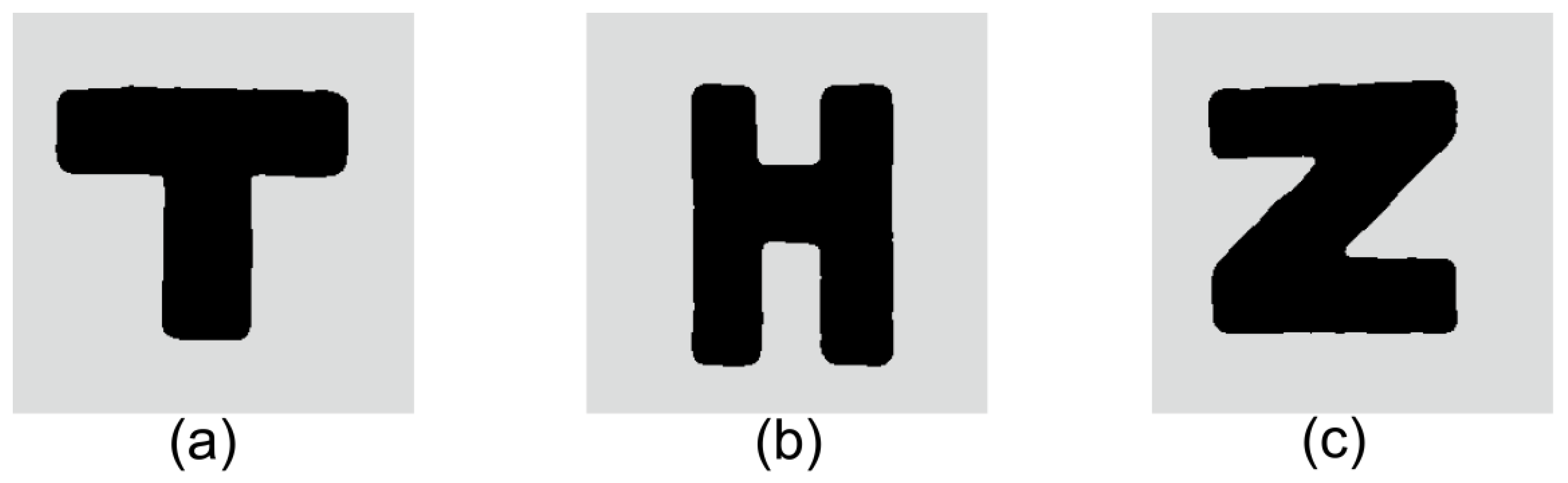
3.2. THz Raster-Scan Imaging Experiment

The THz raster-scan imaging experiment was conducted with the purpose of acquisition of the standard image because there is little distortion in the THz image from the THz raster-scan imaging system. An experimental system for THz raster-scan imaging is illustrated in Figure 6. The source is a Gunn diode oscillator with 0.5 mW of radiated power and 0.28 THz of radiated frequency. The detector is the same as the one mentioned in Section 3.1. Every lens in this system is a convex lens with a 50 mm focal length and a 2 inch aperture. A sample is mounted on the stepper motor platform. The scanning is realized by a two-dimensional motion of the stepper motor platform.

3.3. Implementation Details of Network Training and Image Predicting

The training set includes 33,200 images gained by the translation or rotation of printed Chinese characters. The size of each of these images is 256 × 256. Each image, taken as the standard image, was converted into grayscale. The distorted image was obtained by the method set out in Section 2.3. Figure 7 shows some training image pairs from the training set.
When the network is in training, the initial learning rate is set to 2.7 × 10⁻⁶, the batch size is set to 16, and the minimal learning rate is set to 1 × 10⁻⁶. Additionally, the stochastic gradient descent (SGD) method [34], instead of the Adam optimization algorithm, is used to optimize the network’s loss function.
After training, the predictive network is gained. By smoothing the output of the foregoing predictive network with a 9 × 9 median filter and carrying out the histogram specification, the final corrected image is obtained.

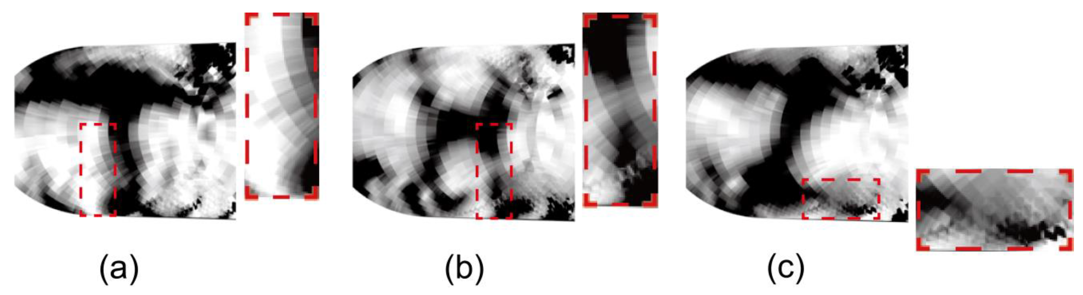
4. Results and Discussion

Figure 8 presents the THz images of the samples obtained from the THz raster-scan imaging experiment (each image took more than 40 min). Comparing Figure 8 with Figure 5b, it can be seen that the THz images obtained from the THz raster-scan imaging experiment are almost identical to the samples themselves. Therefore, the images in Figure 8 can be regarded as the standard images, which are the reference to evaluate the image quality.
Figure 9 is the THz images of the samples acquired by the THz rotation mirror imaging system (the imaging time of each image is about 30 s). As illustrated in Figure 9, there are jagged distortions in the THz images, particularly around the contour.
In Figure 10, the THz images in Figure 9 have been corrected according to the method proposed in this article. Comparing Figure 9 with Figure 10, it can be seen that the twisted contour of sample 1′s THz image has been reverted to a straight one in Figure 10a; a curved and fuzzy part of sample 2′s THz image has been corrected in Figure 10b; and an indistinct part of sample 3′s THz image has become legible in Figure 10c.
For the purpose of assessing the effectiveness of the distortion correction quantitatively, structural similarity index measures (SSIM) [35], are introduced. The SSIM of two images can be calculated as:
S S I M ( x , y ) = ( 2 μ x μ y + c 1 ) ( 2 σ x y + c 2 ) ( μ x 2 + μ y 2 + c 1 ) ( σ x 2 + σ y 2 + c 2 )
where μx is the mean of image x, μy is the mean of image y, 𝜎x is the variance of image x, 𝜎y is the variance of image y, 𝜎xy is the covariance of image x and image y, c1 = (0.01L)2 and c2 = (0.03L)2 are constants used to maintain stability, and L is the dynamic range of pixel values. In particular, the SSIM value is equal to 1 when the two images are identical.
Table 1 demonstrates the quantitative results for the original images and the corrected images. As can be seen in Table 1, the SSIM dramatically increases after distortion correction with the proposed method. This demonstrates that the proposed method based on SRN has the ability to solve the distortion problem of the terahertz rotation mirror imaging system effectively.

5. Conclusions

The scanning mode of the rotation mirror imaging system is circular scanning. When a THz rotation mirror imaging system scans the target, the stepper motor does not need to go through the motion-stop-motion process like the traditional raster-scanning imaging system. Therefore, the imaging speed of the THz rotation mirror imaging system is much higher. Considering that the cost and electronic complexity of a THz rotation mirror imaging system are far lower than those of a THz array scanning imaging system, the THz rotation mirror imaging system is an effective substitute for the THz array scanning imaging system. However, there are a lot of distortions in the imaging results of the THz rotation mirror imaging system due to the imaging principle of the THz rotation mirror imaging system. In this article, a method based on SRN is proposed to implement the imaging enhancement of the terahertz rotation mirror imaging system. In the proposed scale-recurrent network, image restoration is carried out in a coarse-to-fine manner. The imaging principle of the THz rotation mirror imaging system is analyzed. Then, a training set is created using the imaging principle of the THz rotation mirror imaging system. To verify the ability of the proposed method to restore the distorted THz image, an experiment was carried out. SSIM was adopted as the quantitative evaluation index for the distortion correction effect. According to the quantitative results, the SSIM between the standard image and the corrected image is much higher than the SSIM between the standard image and the original image. The above results indicate that the corrected results are much closer to reality. The proposed method based on SRN is an effective and practical method. In the future, the network could be further optimized to achieve a higher SSIM between the standard image and the corrected image. In the experiments of this paper, the imaging time of the THz rotating mirror imaging system is about 1/80 that of the raster-scanning system. The THz rotation mirror imaging system has the advantage of a fast imaging speed. As the THz image distortion is solved, the application of the THz rotation mirror imaging system will be further popularized.

Author Contributions

Conceptualization, C.Y.; methodology, C.Y.; software, Z.L.; validation, D.L. and W.L.; formal analysis, T.W.; writing—original draft preparation, Z.Y. and C.Y.; writing—review and editing, J.L.; supervision, K.W. and Z.Y.; funding acquisition, J.L. All authors have read and agreed to the published version of the manuscript.

Funding

This research was funded by fundamental research funds for the central universities, grant number 2017KFYXJJ029; national natural science foundation of china, grant number 61905232; and national defense pre-research foundation of China, grant number 61422160107.

Institutional Review Board Statement

Not applicable.

Informed Consent Statement

Not applicable.

Data Availability Statement

Data underlying the results presented in this paper are not publicly available at this time but may be obtained from the authors upon reasonable request.

Acknowledgments

The authors thank Tian-Yu Hu for the helpful discussions.

Conflicts of Interest

The authors declare no conflict of interest.

References

  1. Zhang, X.C.; Xu, J. Introduction to THz Wave Photonics; Springer: Berlin/Heidelberg, Germany, 2010; pp. 1–2. [Google Scholar]
  2. Zhao, L.; Hao, Y.-H.; Peng, R.-Y. Advances in the biological effects of terahertz wave radiation. Mil. Med. Res. 2014, 1, 26. [Google Scholar] [CrossRef] [Green Version]
  3. Xing, L.Y.; Cui, H.L.; Shi, C.C.; Han, X.H.; Zhang, Z.Y.; Li, W.; Ma, Y.T.; Zheng, Y.; Zhang, S.N. Experimental Study of PMI Foam Composite Properties in Terahertz. Guang Pu Xue Yu Guang Pu Fen Xi Guang Pu 2015, 35, 3319–3324. [Google Scholar] [PubMed]
  4. Zhang, D.D.; Ren, J.J.; Gu, J.; Li, L.J.; Zhang, J.Y.; Xiong, W.H.; Zhong, Y.F.; Zhou, T.Y. Nondestructive testing of bonding defects in multilayered ceramic matrix composites using THz time domain spectroscopy and imaging. Compos. Struct. 2020, 251, 112624. [Google Scholar] [CrossRef]
  5. Chan, W.; Deibel, J.; Mittleman, D. Imaging with terahertz radiation. Rep. Prog. Phys. 2007, 70, 1325–1379. [Google Scholar] [CrossRef]
  6. Yakovlev, E.V.; Zaytsev, K.I.; Dolganova, I.N.; Yurchenko, S.O. Non-Destructive Evaluation of Polymer Composite Materials at the Manufacturing Stage Using Terahertz Pulsed Spectroscopy. IEEE Trans. Terahertz Sci. Technol. 2015, 5, 810–816. [Google Scholar] [CrossRef]
  7. Tao, Y.H.; Fitzgerald, A.J.; Wallace, V.P. Non-Contact, Non-Destructive Testing in Various Industrial Sectors with Terahertz Technology. Sensors 2020, 20, 712. [Google Scholar] [CrossRef] [Green Version]
  8. Mikhail, G. High-Power Vacuum Electronic Devices from Microwave to THz Band: Way Forward. Electronics 2021, 10, 2436. [Google Scholar] [CrossRef]
  9. Amenabar, I.; Lopez, F.; Mendikute, A. In Introductory Review to THz Non-Destructive Testing of Composite Mater. J. Infrared Millim. Terahertz Waves 2013, 34, 152–169. [Google Scholar] [CrossRef]
  10. Ahi, K.; Anwar, M. Terahertz Techniques: Novel Non-destructive Tests for Detection of Counterfeit Electronic Components. In Proceedings of the Connecticut Symposium on Microelectronics & Optoelectronics (CMOC), Storrs, CT, USA, 9 April 2014. [Google Scholar]
  11. Banerjee, A.; Vajandar, S.; Basu, T. Chapter 13—Prospects in Medical Applications of Terahertz Waves. In Terahertz Biomedical and Healthcare Technologies; Banerjee, A., Chakraborty, B., Inokawa, H., Nath Roy, J., Eds.; Elsevier: Amsterdam, The Netherlands, 2020; pp. 225–239. [Google Scholar]
  12. Mittleman, D.M. Twenty years of terahertz imaging [Invited]. Opt. Express 2018, 26, 9417. [Google Scholar] [CrossRef]
  13. Kiarash, A.; Nathan, J.; Mohammad-Parsa, H.; Navid, A. Survey of terahertz photonics and biophotonics. Opt. Eng. 2020, 59, 1–31. [Google Scholar] [CrossRef]
  14. Chen, L.; Wang, Y.; Xu, D.; Ren, Y.; He, Y.; Li, C.; Zhang, C.; Tang, L.; Yan, C.; Yao, J. Terahertz computed tomography of high-refractive-index objects based on refractive index matching. IEEE Photonics J. 2018, 10, 1–13. [Google Scholar] [CrossRef]
  15. Miccinesi, L.; Consumi, T.; Beni, A.; Pieraccini, M. W-band MIMO GB-SAR for Bridge Testing/Monitoring. Electronics 2021, 10, 2261. [Google Scholar] [CrossRef]
  16. Toker, O.; Brinkmann, M. A Novel Nonlinearity Correction Algorithm for FMCW Radar Systems for Optimal Range Accuracy and Improved Multitarget Detection Capability. Electronics 2019, 8, 1290. [Google Scholar] [CrossRef] [Green Version]
  17. Ahi, K.; Shahbazmohamadi, S.; Asadizanjani, N. Quality control and authentication of packaged integrated circuits using enhanced-spatial-resolution terahertz time-domain spectroscopy and imaging. Opt. Lasers Eng. 2018, 104, 274–284. [Google Scholar] [CrossRef]
  18. Kiarash, A.; Mehdi, A. Advanced terahertz techniques for quality control and counterfeit detection. In Terahertz Physics, Devices, and Systems X: Advanced Applications in Industry and Defense; International Society for Optics and Photonics: Bellingham, DC, USA, 2016. [Google Scholar]
  19. Yeom, S.; Lee, D.S.; Jang, Y.S.; Lee, M.K.; Jung, S.W. Real-time concealed-object detection and recognition with passive millimeter wave imaging. Opt. Express 2012, 20, 9371. [Google Scholar] [CrossRef] [PubMed]
  20. Augustin, S.; Hubers, H.W. Phase-Sensitive Passive Terahertz Imaging at 5-m Stand-Off Distance. IEEE Trans. Terahertz Sci. Technol. 2014, 4, 418–424. [Google Scholar] [CrossRef]
  21. Dolganova, I.N.; Zaytsev, K.I.; Metelkina, A.A.; Yurchenko, S.O. The active-passive continuous-wave terahertz imaging system. J. Phys. Conf. Ser. 2016, 735, 012075. [Google Scholar] [CrossRef] [Green Version]
  22. Mann, C. Real time passive imaging at 250GHz for security: Technology and phenomenology. In Proceedings of the 2009 International Conference on Electromagnetics in Advanced Applications, Torino, Italy, 14–18 September 2009; pp. 1013–1015. [Google Scholar]
  23. Banerjee, A.; Satoh, H.; Elamaran, D.; Sharma, Y.; Hiromoto, N.; Inokawa, H. Performance improvement of on-chip integrable terahertz microbolometer arrays using nanoscale meander titanium thermistor. J. Appl. Phys. 2019, 125, 214502. [Google Scholar] [CrossRef]
  24. Samanta, D.; Karthikeyan, M.; Banerjee, A.; Inokawa, H. Tunable graphene nanopatch antenna design for on-chip integrated terahertz detector arrays with potential application in cancer imaging. Nanomedicine 2021, 16, 1035–1047. [Google Scholar] [CrossRef] [PubMed]
  25. Weg, C.A.; Spiegel, W.V.; Hils, B.; Loffler, T.; Roskos, H.G. Fast active THz camera with range detection by frequency modulation. In Proceedings of the 33rd International Conference on Infrared, Millimeter and Terahertz Waves, Pasadena, CA, USA, 15–19 September 2008. [Google Scholar]
  26. Deliang, Z.; Liwei, H.; Yi, Y.; Yuanzhang, Z.; Xuecou, T.; Jian, C.; Peiheng, W. Bifocal dual reflector system for active terahertz imaging. Appl. Opt. 2018, 57, 3224. [Google Scholar]
  27. Am Weg, C.; von Spiegel, W.; Henneberger, R.; Zimmermann, R.; Loeffler, T.; Roskos, H.G. Fast Active THz Cameras with Ranging Capabilities. J. Infrared Millim. Terahertz Waves 2009, 30, 1281–1296. [Google Scholar] [CrossRef]
  28. Andersson, J.L.R.; Graham, M.S.; Zsoldos, E.; Sotiropoulos, S.N. Incorporating outlier detection and replacement into a non-parametric framework for movement and distortion correction of diffusion MR images. Neuroimage 2016, 141, 556–572. [Google Scholar] [CrossRef] [PubMed] [Green Version]
  29. Rong, J.; Huang, S.; Shang, Z.; Ying, X. Radial Lens Distortion Correction Using Convolutional Neural Networks Trained with Synthesized Images. In Asian Conference on Computer Vision; Springer: Cham, Switzerland, 2016. [Google Scholar]
  30. Tang, Z.; Lin, Y.S.; Lee, K.H.; Hwang, J.N.; Chuang, J.H. ESTHER: Joint Camera Self-Calibration and Automatic Radial Distortion Correction from Tracking of Walking Humans. IEEE Access 2019, 7, 10754–10766. [Google Scholar] [CrossRef]
  31. Mello, A.W.; Book, T.A.; Nicolas, A.; Otto, S.E.; Gilpin, C.J.; Sangid, M.D. Distortion Correction Protocol for Digital Image Correlation after Scanning Electron Microscopy: Emphasis on Long Duration and Ex-Situ Experiments. Exp. Mech. 2017, 57, 1395–1409. [Google Scholar] [CrossRef]
  32. Tao, X.; Gao, H.; Wang, Y.; Shen, X.; Wang, J.; Jia, J. Scale-recurrent Network for Deep Image Deblurring. In Proceedings of the 2018 IEEE/CVF Conference on Computer Vision and Pattern Recognition, Salt Lake City, UT, USA, 18–23 June 2018. [Google Scholar]
  33. Rivara, M.C.; Rodriguez-Moreno, P.A. Tuned Terminal Triangles Centroid Delaunay Algorithm for Quality Triangulation. In International Meshing Roundtable; Springer: Cham, Switzerland, 2018. [Google Scholar]
  34. Lei, Y.; Ying, Y. Fine-Grained Analysis of Stability and Generalization for Stochastic Gradient Descent. Proc. Mach. Learn. Res. 2020, 119, 5809–5819. [Google Scholar]
  35. Horé, A.; Ziou, D. Image quality metrics: PSNR vs. SSIM. In Proceedings of the 20th International Conference on Pattern Recognition, ICPR 2010, Istanbul, Turkey, 23–26 August 2010. [Google Scholar]
Figure 1. Schematic diagram of the THz rotation mirror imaging system.
Electronics 10 02821 g001
Figure 2. (a) Scan path of the THz rotation mirror imaging system and (b) triangulation of the scan points.
Electronics 10 02821 g002
Figure 3. Architecture of the convolutional neural network in the proposed method. (a) Overall structure; (b) architecture of Encoder-Decoder block (E-D block); (c) architecture of Encoder Residual block (Eblock) or Input Residual block (Iblock); (d) architecture of Decoder Residual block (Dblock); (e) architecture of Residual block (Resblock); (f) output Residual block (Oblock).
Electronics 10 02821 g003
Figure 4. Geometric model of the relationship between the incident light and reflected light in THz rotation mirror imaging system.
Electronics 10 02821 g004
Figure 5. (a) is a photograph of our THz rotation mirror imaging system; (b) shows photographs of three samples’ metal layer hidden behind the upper layer of cardboard; (c) is a schematic of the samples’ structure.
Electronics 10 02821 g005
Figure 6. (a) Photograph and (b) schematic diagram of the THz raster-scan imaging system.
Electronics 10 02821 g006
Figure 7. Examples of training image pairs of the training set. (ag) are the standard images; (a1g1) are the distorted images of (ag), respectively.
Electronics 10 02821 g007
Figure 8. THz images of (a) sample 1, (b) sample 2, and (c) sample 3 obtained from the THz raster-scan imaging experiment.
Electronics 10 02821 g008
Figure 9. THz images of (a) sample 1, (b) sample 2, and (c) sample 3 obtained from the THz rotation mirror imaging experiment.
Electronics 10 02821 g009
Figure 10. Corrected images of (a) sample 1, (b) sample 2, and (c) sample 3.
Electronics 10 02821 g010
Table 1. Quantitative results for original images and corrected images.
NameOriginal ImageCorrected Image
SSIMSSIM
Sample 10.51010.7368
Sample 20.46370.6652
Sample 30.49710.6813
Publisher’s Note: MDPI stays neutral with regard to jurisdictional claims in published maps and institutional affiliations.

