Abstract
This paper proposes a contribution to the development of autonomous wake-up radios from the energy supply perspective. More precisely, a rectifier circuit, designed and manufactured in order to provide the energy needed for a quasi passive wake-up radio receiver (WuRx). The WuRx is intended to operate continuously and to ensure a zero energy consumption in standby mode.After the presentation of the said WuRx, the energy requirement for its power supply is defined. Then, the energy harvesting circuit, able to power up the quasi-passive WuRx, is designed, implemented, and then measured. Compared to the state of the art, the energy harvester that we present here is among the few recent designs that replaced the matching network lumped component by butterfly stubs, which brings compactness to the circuit. The rectifier is built on a high efficiency substrate which increases its performance and reduces its form factor.
1. Introduction
The radio interface of a connected device is the part that consumes a lot of energy, even in the absence of information to be transmitted. This causes a great waste of energy, especially, when there is no data exchange. It then becomes necessary to improve the energy efficiency of these interfaces or to find ways to put them into a standby mode which draws as less energy as possible from the main source (battery in most of the cases).
In order to minimize the energy consumption in standby mode, two techniques can be applied, namely duty cycling and wake-up radio. Duty cycling is a technique based on the principle of periodically switching on and off the main radio interface. A communication demand may occur when the main interface is off, so the object initiating the communication should retransmit its request. This implies an increase of the latency and the energy consumption that, for certain application scenarios, is not conceivable.
Wake-up radios may solve the latency problem since they are driving the main radio interface asynchronously. More in detail, WuRx is a very low power consumption secondary radio, driving the power supply of the main radio receiver. The main radio is powered off when there is no information to be transferred. As soon as information is to be transmitted, the WuRx receives a wake-up signal from the device initiating the communication and then switches on the main radio receiver.
WuRx can be classified based on its implementation’s architecture or technologies. The WuRx is based on different architectures, such as super-heterodyne receivers [1], Injection Locking Oscillator (ILO) [2,3,4], super-regenerative [5], or envelope detector PWUR (Passive Wake-Up Radio) [6,7]. With the recent advances in semiconductor technology, WuRx having a power consumption below microwatt and, at the same time, with good performance in terms of range and robustness, it is at the state of the art.
Ideally, the standby mode should result in zero energy consumption, more precisely, it should be exempted from the connected devices’ main energy source. Since the WuRx has a very low-power consumption, the solution of power-supplying it from an energy harvesting circuit is feasible. Depending on the application, several sources of energy may be considered in order to be harvested, such as piezoelectric energy [8], wind [9], hydroelectric [10] and solar energy [11]. However, from our perspective, the Radio frequency (RF) energy harvesting [12,13] draws particular attention.
There are several sources of ambient RF signals that may be considered for harvesting [13], namely Digital Television Broadcasting (DTV), cellular networks, or wireless local area networks (WLAN) access points. Depending on whether one is in a rural, urban or semi-urban environment, one of the sources can be dominant over the others.
In Cameroon, as in other developing countries, the increasing number of mobile phone users over the last two decades has made possible the installation of a very large number of base stations, transmitting signals at sufficient power levels at 850/900/1800/2100/2600 MHz, using the same frequencies as in Western Europe. The potential of harvesting RF energy at some of these frequencies is available in [8], showing that the harvested powers range from 39 nW/cm2 for the GSM 900 MHz frequency band to 460 nW/cm2 for the DTV 470–610 MHz frequency band.
In [14], energy harvester circuit has been designed operating at 900 MHz. At an input power of 0 dBm, 450 μW power was recovered with the conversion efficiency of 45%. On another note, the experiment in [15] proves the RF efficient energy harvesting from a DTV-UHF (Ultra High Frequency) tower situated 4.1 km away. The reported harvested power is 60 μW and is sufficient to continuously supply a commercial thermometer/hygrometer. In the latter case, the Effective Radiated Power (ERP) is 960 kW and the television tower is operating between 674 and 680 MHz. Another implementation of DTV EH (Energy Harvesting) is presented in [16]. An average power of 20 μW is harvested from a television tower.
Another implementation of DTV EH (Energy Harvesting) is presented in [16]. An average power of 20 μW is harvested from a television tower situated 6.6 km away. These examples can be extended to GSM 1800 MHz and even 3G/4G mobile networks by considering that the installation of the base station for mobile communication follows the same rule.
Moreover, WLAN (Wireless Local Area Network) has become an omnipresent network in almost all working environments, thus giving the possibility to harvest RF energy from such kind of signals. The authors in [17] show that it is possible to harvest energy from Wi-Fi sources operating at 2.4/5 GHz to power supply a large number of devices, such as low-power cameras, temperature sensors, etc. Another demonstrative implementation [18] has proved the highest conversion efficiency (33.7%) when placed at 40 cm distance from the source, yielding to a power of 76.3 μW at the output.
The main advantage of the RF energy harvesting is that it is permanently available. Indeed, compared to RF harvesting, the availability of other sources of energy, i.e., solar or wind is conditioned mainly by the weather. It is in fact the most suitable source of energy for the applications that require continuous supply.
The aim of this work is to couple two techniques, which are the wake-up radio (WuRx) and RF energy harvesting, in order to propose an RF interface with a standby mode independent from main energy source. More precisely, the approach proposed here is to power supply the wake-up radio by the energy collected by the RF energy harvesting system. This is particularly efficient for low duty cycle connected devices as, for example, most of the scenarios in the Internet of Things (IoT) context.
In some other scenarios, especially those where the connected device is far away from the energy source, the energy collected by the harvesting circuit is not enough. In these particular cases, wireless power transfer solutions may be employed [19]. The RF circuit which will be employed has the same characteristics, since the received power levels and signal bandwidths are the same.
On one side, we are assisting to a decrease in terms of energy consumption of the WuRx and, on the other side, to an increase of the energy harvesting circuits’ efficiency. It becomes obvious that the combination of the two techniques is feasible. The association of wake-up radio energized by RF energy harvesting circuits will help propose “deploy and forget” devices in the context of the Internet of Things.
The rest of this paper is organized as follows: Section 2 briefly describes the quasi-passive WuRx to be power-supplied by an energy harvesting circuit. Then, the general considerations of the energy harvester circuits are given. The proposed circuit with performance improvement is presented in Section 3 as well as the circuit-system simulation results together with the obtained results after implementation. Section 4 gives the conclusion and draws the perspectives of this work.
2. Quasi-Passive Wake-Up Radio Receiver Power-Supplied by Energy Harvesting Circuit
2.1. Quasi Passive Wake-Up Radio
The quasi-passive wake-up radio to be power-supplied uses a wide-band multicarrier signal as the identifier. This original approach allows to get rid of an MCU (microcontroller unit), classically used to decode the identifier and, so, to reduce even more the energy consumption. Its architecture is described in detail in [20] and includes, on the one hand, a passive part made up of a power divider, two envelope detectors together with their impedance matching circuits and two banks of filters. On the other hand, the active part includes a voltage subtractor and a Schmidt trigger. An experimental validation of this WuRx was presented in [21]; the only components that require to be power-supplied are the subtractor and the Schmidt trigger. Due to their low-power demands, the off-the-shelf components ISL28194 and TLV3691 were chosen to implement the wake-up radio’s subtractor and trigger functions. Their respective consumption is given to be 1.65 μW and 375 nW, thus, the total instantaneous consumption is 2.025 μW. This power consumption may be reduced even more if a dedicated ASIC (Application Specific Integrated Circuit) is designed. However, the power level is small enough in order to envisage to power-supply the WuRx’s active part from the energy collected by a dedicated RF energy harvester as shown in Figure 1.
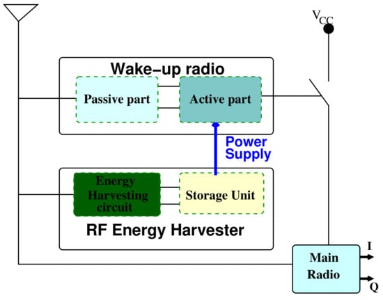
Figure 1.
The proposed autonomous wake up radio. The active part of the wake-up radio is power-supplied by an RF energy harvesting circuit.
2.2. Overview of the RF Energy Harvesting Circuits
Energy harvesters have been the subject of intense studies for several years. Without being exhaustive, we will present here some works on this topic, mainly focused on the RF energy harvesters. To the best of our knowledge, the harvesting of RF energy as it stands today began in 2005 with the work presented in [22]. In this work, a series of 4 passive antennas made of transmission lines (engraved on the FR4 substrate) interlaced in a square spiral was used, each of them matched in impedance with a rectifier using a double diode bridge HSMS2820. In this work, the intertwining of antennas aims at collecting the maximum of energy on a physical surface different from the effective surface of an antenna, at the considered frequency (here 915 MHz). The result obtained was a power of 80 mW harvested at a distance of 20 cm for 5 W emitted power. In Table 1,some recent energy harvesting circuits are presented with their characteristics.

Table 1.
Characteristics of some recent RF energy harvesters and of the proposed work.
The block diagram of a common RF energy harvester is presented in Figure 2. It is made up of the antenna, the input HF filter which is used for impedance matching between the antenna and the rectifier, the rectifier’s diode, the DC low-pass filter which rejects higher-order harmonics and the storage unit or load. Depending on the application, the storage unit may be a battery or a super-capacitor.
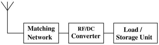
Figure 2.
Block diagram of RF energy harvester.
In general, the energy harvester has the role of transforming the power contained in electromagnetic waves available at its input, into a DC voltage susceptible to energize the load (the WuRx’s active part in our case). It is mainly characterized by its conversion efficiency given by the following expression:
where is the instantaneous power at the output of the storage unit and is the instantaneous power at the input of the rectifier.
In RF energy harvesting, Schottky diodes are used rather than any other type of diodes. The small signal model is presented in Figure 3 and the electrical parameters of some common Schottky diodes are listed in Table 2.
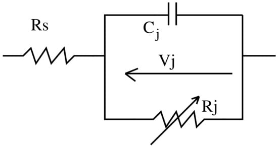
Figure 3.
Small signal model of a diode.
Table 2.
Parameters of some commonly used Schottky diodes.
In the equivalent model depicted in Figure 3, represents the series resistance, and are respectively the junction capacitance and the junction resistance. The junction capacitance is given by:
where is zero bias diode’s junction capacitance, is the output voltage across the load resistance and is the voltage across the semi-conductor metal junction.
The junction resistance is variable and depends on the externally applied bias current , on the saturation current , on the ideality factor n, and on the temperature T. It is expressed as:
These parameters are impacting the rectifier’s overall efficiency. More globally, the overall efficiency depends on how the amount of RF power arrives at the diode level and how the amount of power is delivered to the load (Equation (1)).
As explained in [30], it takes into account the matching efficiency , the conversion efficiency and transfer efficiency from the diode’s output to the load . It can be expressed as:
The matching efficiency depends on the reflection coefficient. Minimizing this reflection coefficient, especially at low power levels, Equation (5) leads to an increase in matching efficiency.
where is the source internal impedance. In our case, it corresponds to the rectifier’s antenna impedance. is the diode impedance. As shown in [31], the diode’s conversion efficiency is defined by:
where is a dynamic variable which depends on the input RF power, also called forward bias turn-on angle. The resistance models the rectifier’s load. It corresponds to the input impedance of the storage unit.
The rectifier’s antenna surface plays an important role in the amount of power collected by the energy harvester. Indeed, one simple model is to consider the free space transmission. In this case, the RF power received by the antenna is expressed by:
where:
- : RF power level at the antenna’s input;
- : power radiated by the transmitter;
- : gain of transmitting antenna;
- : antenna’s effective aperture;
- r: distance between the transmitting and the receiving antennas.
The effective area of the antenna can be computed if the typical case [19] of a 4 dBi gain and a frequency of 2.45 GHz is considered:
where is the wavelength (m) and G is the linear gain of the antenna.
2.3. Rectifier Architectures
The study presented in [32] evokes the three main topologies which are shown in Figure 4. These topologies are the double diode bridge, shunt single diode, and single mounted series diode.
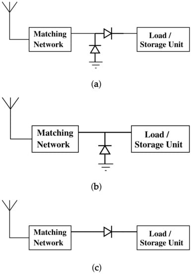
Figure 4.
Topologies of energy harvester circuits. (a) Diode bridge. (b) Shunt topology. (c) Series-mounted diode.
The choice of one particular topology is mainly guided by the conversion efficiency. Depending on the frequency, input power and diode type, one topology may be more convenient than another. For our application case, which is concerned with low RF power levels (below −10 dBm), and a frequency around 2.45 GHz, we have used the SMS 7630 diode. As can be remarked from Figure 5, the circuit with the diode mounted in series is the most suitable for the present application, since it gives the higher conversion efficiency at low power levels ranging from −50 dBm to −10 dBm. The diode bridge and shunt topology have conversion efficiencies less than 1%.
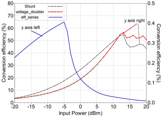
Figure 5.
Conversion efficiencies of series, shunt and bridge harvester using SMS 7630 diodes.
2.4. Diode Selection
As in [25], several Schottky diodes were considered and the ones which are the most affordable were tested in terms of conversion efficiency. As can be seen from Figure 6, the SMS 7630 diode offers better conversion efficiency for low input powers, especially, in the range of harvested ambient RF power.
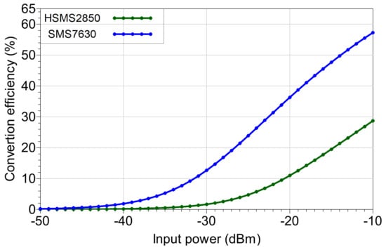
Figure 6.
Conversion efficiencies of HSMS 2850 and SMS 7630-based rectifiers.
In both cases (SMS7630 and HSMS250), the input circuit was designed in such a way that the reflection coefficient S11 is around −20 dB, as depicted in Figure 7.
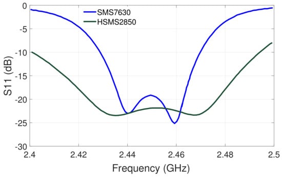
Figure 7.
Reflection coefficient S11 (dB) at the rectifier’s input.
The load of the rectifier circuit plays an important role in the increase of the rectifier’s efficiency. Figure 8 shows the conversion efficiency of the HSMS2850 and SMS7630 diode-based rectifiers, for −30 dBm input power. As can be expected, for various load resistance values, the harvester based on the SMS7630 diode has better conversion efficiency. Indeed, this conversion efficiency is 12.7% at maximum compared to 2% of the rectifier based on HSMS2850.
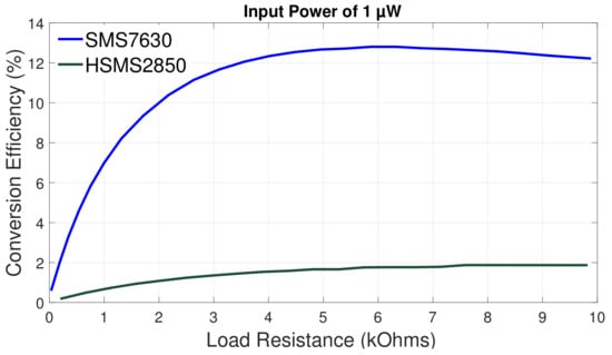
Figure 8.
Conversion efficiency results of the HSMS 2850 and of the SMS 7630 diode-based harvesters.
3. Analysis of the Proposed Rectifier Circuit
In this context, we have proposed a rectifier circuit having a double stub topology as matching circuit and optimized to have good performance at low power levels. Figure 9 presents the layout of the proposed rectifier circuit as part of the energy harvester. Taking into account the evoked design considerations, the rectifier is based on a Skyworks’ SMS 7630 diode and made up using the microstrip technology. This technology was chosen in order to design the impedance matching circuit and is preferred as compared to lumped components because it is less dispersive at high frequencies.
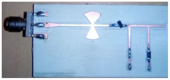
Figure 9.
Photograph of the manufactured rectifier circuit.
As stated, the harvester is made up of butterfly radial stubs for large bandwidth impedance matching. Compared to the classical stub, the butterfly one brings a certain compactness. Moreover, the choice of those radial stubs helps to get good impedance matching around 2.45 GHz, as shown in Figure 10. The stub dimensions were optimized in order to have best impedance matching for low input power levels.
Figure 10.
Simulated reflection coefficient (dB) at the rectifier’s input for different power levels.
The rectifier’s central frequency was optimized at 2.45 GHz but, due to manufacturing constraints, the measured central frequency is shifted down to 2.1 GHz. At an input power level of −40 dBm, the reflection coefficient was measured on the fabricated prototype (Figure 11) with a Vector Network Analyzer. Figure 9 presents the implementation of the proposed high-efficiency harvester optimized and printed on a Rogers Duroid (RO4350B) substrate. This hydrocarbon ceramic laminate has a superior high-frequency performance. The dielectric constant is 3.66, it has a dissipation factor of 0.0031, the substrate thickness is 0.51 mm, and the conductor thickness is 17.5 μm.
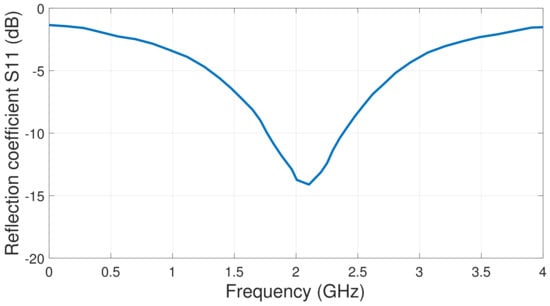
Figure 11.
Measured reflection coefficient (dB) at the rectifier’s input for −40 dBm input power level.
The DC filter at the output of the rectifier was implemented with a 0.1 nF capacitor in parallel with a 5.1 kΩ resistor. These specific values have been chosen because they are maximizing the output DC voltage. The maximum efficiency is obtained at a specific input power, which mainly depends on the Schottky’s diode characteristics. In our specific case, the received power level allowing the maximum efficiency (65%) is equal to −5 dBm.
In Figure 12, the simulated and measured output voltages are presented. A precision millivoltmeter was employed for the measurement of the rectifier’s DC output voltage. In both cases, simulation and measurement, the frequency corresponding to the minimum of the reflection coefficient (2.45 GHz in simulation and 2.1 GHz in measurement) was used.
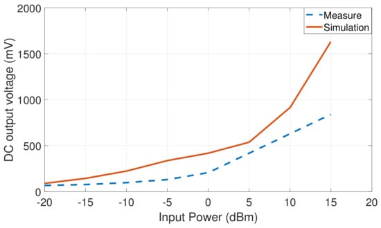
Figure 12.
The simulated and measured output voltage of the RF energy harvester.
For the specific case of a quasi-passive wake-up radio, which is to be power-supplied with this circuit, the 2.025 μW power corresponds to an output voltage of 101.6 mV for the existing load resistance of 5.1 kΩ. According to the measurement results, this output voltage is obtained for input RF power levels higher than −5 dBm.
4. Conclusions
The work presented in this paper covers the design and implementation of an RF energy harvester circuit, which is designed to power a wake-up radio and make it autonomous. In some scenarios, such a combination of the WuRx and the energy collecting system, as well as the technique used for its implementation, give the possibility to harvest a sufficient amount of energy for a continuous power supply of the WuRx. The future work should focus on the reduction of the power of WuRx and on the improvement of RF energy harvesting strategy, by increasing the rectifier’s efficiency, reducing the size of devices and implementation in a working environment.
Author Contributions
Investigation, C.A.F.; Methodology, F.D.H.; Supervision, E.T.; Validation, P.T. and G.V. All authors have read and agreed to the published version of the manuscript.
Funding
This work was support by French Embassy in Cameroon (SCAC).
Acknowledgments
We acknowledge the cooperation service of the French Embassy in Cameroon (SCAC) for financial support of this work.
Conflicts of Interest
The authors declare no conflict of interest.
References
- Huang, X.; Ba, A.; Harpe, P.; Dolmans, G.; de Groot, H.; Long, J.R. A 915 MHz, Ultra-Low Power 2-Tone transceiver with enhanced interference Resilience. IEEE J. Solid-State Circuits 2012, 47, 3197–3207. [Google Scholar] [CrossRef]
- Wada, T.; Ikebe, M.; Sano, E. 60-GHz, 9-nW wake-up receiver for short-range wireless communications. In Proceedings of the European Solid-State Circuits Conference (ESSCIRC), Bucharest, Romania, 16–20 September 2013; pp. 383–386. [Google Scholar]
- Pandey, J.; Shi, J.; Otis, B. A 120 μW MICS/ISM band FSK receiver with a 44 μW low-power mode based on injection-locking and 9x frequency multiplication. In Proceedings of the IEEE International Solid-State Circuits Conference, San Francisco, CA, USA, 20–24 February 2011; pp. 460–462. [Google Scholar] [CrossRef]
- Yan, H.; Macias-Montero, J.G.; Akhnoukh, A.; de Vreede, L.C.; Long, J.R.; Pekarik, J.J.; Burghartz, J.N. A 120 μW fully-integrated BPSK receiver in 90 nm CMOS. In Proceedings of the IEEE Radio Frequency Integrated Circuits Symposium, Anaheim, CA, USA, 23–25 May 2010; pp. 277–280. [Google Scholar] [CrossRef]
- Rezaei, V.D.; Shellhammer, S.J.; Elkholy, M.; Entesari, K. A fully integrated 320 pJ/B OOK super-regenerative receiver with −87 dBm sensitivity and self-calibration. In Proceedings of the IEEE Radio Frequency Integrated Circuits Symposium, San Francisco, CA, USA, 22–24 May 2016; pp. 222–225. [Google Scholar]
- Shekhar, C.; Varma, S.; Radhakrishna, M. A 2.4 GHz passive wake-up circuit for power minimization in wireless sensor nodes. In Proceedings of the IEEE Region 10 Conference, Macao, China, 1–4 November 2015; pp. 1–6. [Google Scholar] [CrossRef]
- Kamalinejad, P.; Keikhosravy, K.; Magno, M.; Mirabbasi, S.; Leung, V.C.; Benini, L. A high-sensitivity fully passive wake-up radio front-end for wireless sensor nodes. In Proceedings of the IEEE International Conference on Consumer Electronics (ICCE), Las Vegas, NV, USA, 10–13 January 2014; pp. 209–210. [Google Scholar] [CrossRef]
- Pinuela, M.; Mitcheson, P.D.; Lucyszyn, S. Ambient RF energy harvesting in urban and semi-urban environments. IEEE Trans. Microw. Theory Tech. 2013, 61, 2715–2726. [Google Scholar] [CrossRef]
- Jushi, A.; Pegatoquet, A.; Le, T. Wind energy harvesting for autonomous wireless sensor networks. In Proceedings of the Euromicro Conference on Digital System Design, Limassol, Cyprus, 31 August–2 September 2016; pp. 301–308. [Google Scholar] [CrossRef]
- Aqel, M.O.A.; Issa, A.; Qasem, E.; El-Khatib, W. Hydroelectric generation from water pipelines of buildings. In Proceedings of the International Conference on Promissing Electronic Technologies, Deir El-Balah, Palestine, 3–4 October 2018; pp. 63–68. [Google Scholar] [CrossRef]
- Sharma, H.; Haque, A.; Jaffery, Z.A. An efficient solar energy harvesting system for wireless sensor nodes. In Proceedings of the 2nd International Conference on Power Electronics, Intelligent Control and Energy Systems (ICPEICES), Delhi, India, 22–24 October 2018; pp. 461–464. [Google Scholar] [CrossRef]
- Psomas, C.; Krikidis, I. Ambient RF energy harvesting with non-linearities, in large-scale networks. In Proceedings of the IEEE Global Communications Conference (GLOBECOM), Big Island, HI, USA, 9–13 December 2019. [Google Scholar] [CrossRef]
- Sidhu, R.K.; Ubhi, J.S.; Aggarwal, A. A survey study of different RF energy sources for RF energy harvesting. In Proceedings of the 2019 International Conference on Automation, Computational and Technology Management (ICACTM), London, UK, 24–26 April 2019; pp. 530–533. [Google Scholar] [CrossRef]
- Uzun, Y. Design and Implementation of RF Energy Harvesting System for Low-Power Electronic Devices. J. Electron. Mater. 2016. [Google Scholar] [CrossRef]
- Sample, A.; Smith, J.R. Experimental results with two wireless power transfer systems. In Proceedings of the 4th International Conference on Radio and Wireless Symposium, RWS’09, Piscataway, NJ, USA, 16–18 January 2009. [Google Scholar] [CrossRef]
- Nishimoto, H.; Kawahara, Y.; Asami, T. Prototype implementation of wireless sensor network using TV broadcast RF energy harvesting. In Proceedings of the 12th ACM International Conference Adjunct Papers on Ubiquitous Computing Adjunct, Copenhagen, Denmark, 26–29 September 2010; pp. 373–374. [Google Scholar] [CrossRef]
- Talla, V.; Kellogg, B.; Ransford, B.; Naderiparizi, S.; Gollakota, S.; Smith, J.R. Powering the next billion devices with Wi-Fi. In Proceedings of the ACM Conference on Emerging Networking Experiments and Technologies, Heidelberg, Germany, 1–4 December 2015. [Google Scholar] [CrossRef]
- Hong, H.; Cai, X.; Shi, X.; Zhu, X. Demonstration of a highly efficient RF energy harvester for Wi-Fi signals. In Proceedings of the International Conference Microwave and Millimeter Wave Technology (ICMMT), Shenzhen, China, 5–8 May 2012; Volume 5, pp. 1–4. [Google Scholar] [CrossRef]
- Olgun, U.; Chen, C.C.; Volakis, J.L. Wireless power harvesting with planar rectennas for 2.45 GHz RFIDs. In Proceedings of the URSI International Symposium on Electromagnetic Theory, Berlin, Germany, 16–19 August 2010; pp. 329–331. [Google Scholar] [CrossRef]
- Hutu, F.; Khoumeri, A.; Villemaud, G.; Gorce, J.M. A new wake-up radio architecture for wireless sensor networks. EURASIP J. Wirel. Commun. Netw. 2014. [Google Scholar] [CrossRef][Green Version]
- Hutu, F.; Kibloff, D.; Villemaud, G.; Gorce, J.M. Experimental validation of a wake-up radio architecture. In Proceedings of the IEEE Radio Wireless Symposium, Austin, TX, USA, 24–27 January 2016; pp. 155–158. [Google Scholar] [CrossRef]
- Mi, M.; Mickle, M.H.; Capelli, C.; Swift, H. RF energy harvesting with multiple antennas in the same space. IEEE Antennas Propag. Mag. 2005, 47, 100–106. [Google Scholar] [CrossRef]
- Almoneef, T.S. Design of a rectenna array without a matching network. IEEE Access 2020, 8. [Google Scholar] [CrossRef]
- Tafekirt, H.; Pelegri-Sebastia, J.; Bouajaj, A.; Reda, B.M. Sensitive triple-band rectifier for energy harvesting applications. IEEE Access 2020, 8. [Google Scholar] [CrossRef]
- Wang, M.; Chen, J.; Cui, X.; Li, L. Design and Fabrication of 5.8 GHz RF Energy Harvesting Rectifier. In Proceedings of the Cross Strait Quad-Regional Radio Science and Wireless Technology Conference (CSQRWC), Taiyuan, China, 18–21 July 2019. [Google Scholar] [CrossRef]
- Mansour, M.M.; Kanaya, H. High-Efficient Broadband CPW RF Rectifier forWireless Energy Harvesting. IEEE Microw. Wirel. Components Lett. 2019, 29, 1–3. [Google Scholar] [CrossRef]
- Lin, C.-H.; Chiu, C.-W.; Gong, J.-Y. A Wearable Rectenna to Harvest Low-Power RF Energy for wireless healthcare applications. In Proceedings of the 11th International Congress on Image and Signal Processing, BioMedical Engineering and Informatics (CISP-BMEI), Beijing, China, 13–15 October 2018. [Google Scholar] [CrossRef]
- Mouapi, A.; Kandil, N.; Kamani, G.V. A Miniature Rectifier Design for Radio frequency Energy Harvesting applied at 2.45 GHz. In Proceedings of the IEEE International Conference on Environment and Electrical Engineering and Commercial Power System Europe (EEEIC/I&CPS), Palermo, Italy, 12–15 June 2018; pp. 1–5. [Google Scholar] [CrossRef]
- Li, C.; Yu, M.; Lin, H. A Compact 0.9-/2.6-GHz Dual-Band RF Energy Harvester Using SiP Technique. IEEE Microw. Wirel. Components Lett. 2017, 27, 666–668. [Google Scholar] [CrossRef]
- Hemour, S.; Zhao, Y.; Lorenz, C.H.P.; Houssameddine, D.; Gui, Y.; Hu, C.M.; Wu, K. Towards low-power high-efficiency RF and microwave energy harvesting. IEEE Trans. Microw. Theory Tech. 2014, 62, 965–976. [Google Scholar] [CrossRef]
- McSpadden, J.O.; Fan, L.; Chang, K. Design and experiments of a high-conversion-efficiency 5.8-GHz rectenna. IEEE Trans. Microw. Theory Tech. 1998, 46, 2053–2060. [Google Scholar] [CrossRef]
- Marian, V.; Vollaire, C.; Verdier, J.; Allard, B. Potentials of an Adaptive Rectenna Circuit. IEEE Antennas Wirel. Propag. Lett. 2011, 10, 1393–1396. [Google Scholar] [CrossRef]
Publisher’s Note: MDPI stays neutral with regard to jurisdictional claims in published maps and institutional affiliations. |
© 2021 by the authors. Licensee MDPI, Basel, Switzerland. This article is an open access article distributed under the terms and conditions of the Creative Commons Attribution (CC BY) license (https://creativecommons.org/licenses/by/4.0/).