Abstract
A high proportion of photovoltaic (PV) connections to a low-voltage distribution network (LVDN) causes serious voltage problems. In order to ensure voltage stability for renewable energy networks, we propose a distributed reactive voltage control strategy that is event-triggered. The voltage information of the PV nodes is transmitted to the upper layer of the communication network, where the agent calculates the output set value of the PV inverter. The underlying control strategy is based on the voltage sensitivity matrix, and the upper-level control strategy is based on an event-triggered consensus protocol. This strategy can accommodate the requirements for multi-time modeling and control. We verified the convergence of the event-triggered control algorithm using numerical analysis and proved the reduction of the communication times. We conducted case studies and simulation experiments to verify the effectiveness of our proposed voltage control strategies.
1. Introduction
High fossil fuel consumption has caused many problems, such as energy crises and environmental pollution. Under the dual pressure of energy demand and environmental protection, distributed generation technology using renewable energy has gradually attracted worldwide attention [1,2].
The traditional distribution network is a passive network, where the power flows from the substation to the load in one direction, and voltage fluctuation is very rare [3]. Traditional voltage control methods mainly use on-load regulating transformers (OLTC), switching capacitors (SC), and step voltage regulators (SVR). When the network includes high penetration distributed generation (DG), OLTC and SC are not able to respond to voltage changes in time. The intermittency, randomness, and volatility of DGs influences the power flow and causes power quality problems such as voltage violation, three-phase imbalance, and increasing harmonic content to the low-voltage distribution network (LVDN). Therefore, voltage regulation has become a focal concern in LVDN with high permeability and renewable energy access [4].
For the voltage violation problem in a LVDN, researchers found that the resistance to the reactance (R/X) ratio of power lines is directly related to the voltage sensitivity [5]. When R > X, the influence of the active power on the voltage is more significant. When R < X, the influence of the reactive power on the voltage is more significant. The network voltage can be controlled by adjusting the active power and reactive power if R = X in the LVDN [6,7].
Control strategies based on the voltage sensitivity are gaining popularity [8,9,10,11]. In these methods, voltage regulation problems are solved using the sensitivity matrix, and the control mechanism include the grid-connected converter of DG system [8,9,10], the capacitor [8], and energy storage [10].
A centralized reactive power control model was proposed [12] that considers the centralized reactive power management and coordination of voltage-dependent reactive power characteristics.
Centralized control uses the central controller to collect information from each node and issues instructions to control the DG, OLTC, load, and other equipment [8,9,10,12]. Centralized methods are easy to implement, but when a large number of DGs are connected to the low-voltage power grid, the topological structure is complicated and the communication systems are restricted, so a distributed voltage control strategy is widely used. A distributed voltage adaptive control method was proposed [13,14]; a distributed frequency method was also developed, which aims to minimize the cost of power generation [15].
A multi-agent system (MAS) is a system composed of multiple agents [16]. Each agent has certain capabilities of perception, communication, calculation, and execution. Each agent perceives local information and interacts with its neighbors, and then the control strategy is given by optimized calculation, communication, and judgment. In one study, the researchers regarded the distributed power sources and voltage regulating devices as agents and proposed a hierarchical control strategy in the framework of a multi-agent system, which settled the reactive power sharing inaccuracy among the distributed generations associated with mismatched line impedance [17]. Based on the MAS, researchers took the voltage cost and renewable energy active power reduction cost as targets, minimized these objectives through distributed optimization algorithms, and adjusted the active and reactive power output of distributed power sources to achieve voltage control [18].
The limitation of the distributed voltage control strategy based on the MAS is that it requires a lot of communication to effectively control the network. To reduce the communication frequency between agents and reduce the energy loss caused by communication, Astrom [19] and Arzen [20] proposed event-triggered control (ETC), which is different from traditional constant time period communication. Due to the advantages of ETC in saving online resources, it was applied to the consistency of the MAS by many researchers [21]. The basic models and algorithms of centralized and distributed ETC were introduced in the literature [22,23]. When the measured value reaches the preset threshold in distributed ETC, one or more events are triggered, which cause the communication and update the multi-agent state [24]. Others propose a new distributed event-triggered algorithm to solve the multi-agent consistency problem [25]. The introduction of event-triggered communication in the consensus protocol not only enables the agent to reach the target state, but also reduces the communication to a certain extent. ETC for MASs is more complicated and challenging, so future research includes designing an appropriate control scheme to improve reliability and fast real-time control.
To address the problems of continuous communication in MAS, a high complexity in designing distributed ETCs, and the limitations of system dynamics, we propose a distributed control strategy for photovoltaic (PV) inverters based on the voltage sensitivity matrix. We used event-triggered control to regulate the voltage within 0.95 p.u. to 1.05 p.u. and realize reactive power sharing. We regarded the reactive output of PV inverters as the control object, and we developed a distributed approach of ETC to solve the multi-agent consistency problem. This method has the advantage of increasing the flexibility and stability of network communication over centralized methods [4,8,9,10,12]. Compared with the distributed methods in the literature [13,14,15,16,17,18], this method achieves consistency of the reactive power to the capacity ratio and reduces the number of communications.
This paper uses the sensitivity matrix and graph theory. In Section 2, these basic theories are introduced. In Section 3, a distributed control strategy is proposed. The underlying control approach is based on the sensitivity matrix, and the upper control strategy is a consensus algorithm based on MAS. An event-triggered consensus algorithm is proposed in Section 4. Algorithm implementation is shown in Section 5. Simulation experiments are provided in Section 6 to verify the effectiveness of the proposed method. Section 7 concludes the paper.
2. Preliminaries
2.1. Sensitivity Analysis
The voltage-to-power sensitivity matrix should include the active and reactive components of the voltage to power [26]. For an n-node radiation distribution network, the sensitivity matrix is given by
where Un denotes the voltage of node n, Pn and Qn represent the active and reactive power in node n, and SP and SQ represent the sensitivity coefficients of the active and reactive components.
The voltage offset formula of node n is given by
where U0 denotes the nominal voltage and Ui represents the voltage of node i. Rij and Xij are the common resistance and common reactance of node 0 to nodes i and j. When i = j, Rii and Xii represent the self-resistance and self-reactance of node 0 to node i.
We derive the active and reactive components in Equation (2) to obtain
From Equations (3)–(5), it can be shown that the voltage change is determined by the sum of the power increments of each node in the distribution network, namely
Once the topology and parameters of the distribution network are determined, the sensitivity matrix can be computed using Equations (3) and (4). It can also be seen from Equation (5) that the primary cause of the voltage change at node i is the variation in the active and reactive power injected by each node.
For node i, the voltage increment is not only related to its own power increment, but also to other nodes’ power increments.
Since Rii > Rij, Xii > Xij, it can be seen that the change of the injected power of node i has the greatest impact on its voltage. Therefore, controlling the injected power of the node can effectively suppress the voltage over-limit phenomenon in the distribution network.
2.2. Algebraic Graph Theory
As the network communication topology between agents involves the knowledge of graph theory, we first discuss the concept of graph theory. A graph G is composed of a set of vertices ν and edges ε. When the edges of the graph G are bidirectional with its corresponding vertices, it is called an undirected graph; otherwise, it is a directed graph.
For an undirected graph G, the adjacency matrix A = (aij)n×n is the n × n matrix with elements given by
where ε is the subset of edges.
The degree di of node νi is determined by matrix D = diag[d1,d2…,dN], whose elements represent the number of adjacent nodes to node νi, and is the set of neighbor nodes of node νi. The symmetric positive semidefinite Laplacian matrix of graph G is defined as L = D − A. For a connected graph, the Laplacian matrix contains a single zero eigenvalue, and the corresponding eigenvector is a unit vector. The eigenvalues of the Laplacian matrix can be denoted as 0 = λ1 ≤ λ2 ≤…λN.
3. Distributed Voltage Control Based on the Sensitivity Matrix
In this section, a voltage control method is proposed based on the sensitivity matrix characteristics and algebraic graph theory, and a control system model for 380 V LVDN with PV connection is developed to realize proportional distributed reactive power sharing control.
3.1. System Architecture
To realize the distributed voltage control, a two-layer control system architecture is constructed. We model the bottom layer LVDN with high penetration of PV based on a real model as a directed graph G with 27 nodes, in which edges represent transmission lines and circled nodes represent 15 groups of PV units and power consumers (see Figure 1). Circled nodes are connected through transmission lines and coupled to the grid.
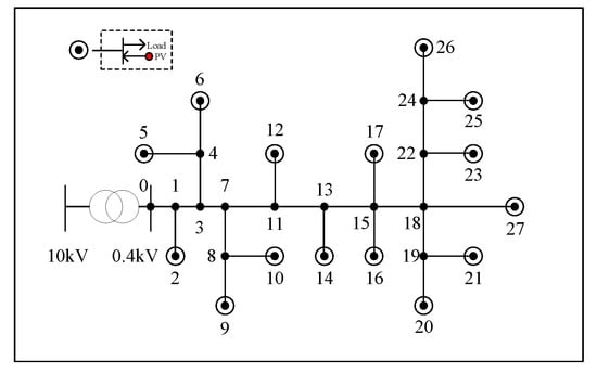
Figure 1.
Low-voltage Distribution Network Model with 27 nodes, where circled nodes represent a set of photovoltaic (PV) inverters and loads (2,5,6,9,10,12,14,16,17,20,21,23,25,26,27).
Each PV unit connects to an agent that is adapted to measure, compute, and adjust outputs. The top layer communication network is shown in Figure 2. Each agent only interacts with its neighbors, where degree di = 2. Agent i measures its local information and adjacent agents’ information, i.e., pi, qi, ui, pj, qj, and uj, and then controls the voltage by control laws, which are given in Section 3.2 and Section 3.3.
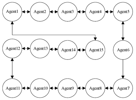
Figure 2.
Upper Layer Communication Network, where 15 agents represent the 15 PV inverters in Figure 1.
3.2. Distributed Voltage Control Based on Sensitivity Matrix
The PV inverter in the LVDN has the ability to regulate the reactive power. Based on the analysis of sensitivity in Section 2.1, we can see that the reactive components of sensitivity matrix SQ can be expressed by Equation (4).
The voltage increment of node i is related to the reactive power increment of each node. Since Xii > Xij, the reactive power increment of node i has the greatest impact on its voltage.
In this section, each PV node only obtains its own voltage information. It adjusts the voltage by controlling the reactive output of the inverter and constructs a q-u function equation similar to droop control for voltage control. The reactive output value at the next moment is equal to the reactive output at the previous moment minus the product of the voltage deviation and the sensitivity coefficient, which is formulated as
where Q(t + 1) = [qi(t + 1)]n×1, Q(t) = [qi(t)]n×1, U(t) = [ui(t)]n×1 are the column vectors of reactive power output and voltage amplitude. U0 denotes standard voltage. KSQ = [Xii/U0]n×1 is the sensitivity coefficient.
According to Equation (7), the distributed control law can be given by
The control law (8) indicates that when the voltage of the LVDN connected to high-permeability renewable energy exceeds the upper limit, the PV inverter absorbs reactive power. On the contrary, the PV inverter generates reactive power when the voltage exceeds the lower limit.
Remark 1.
Parameter SQ in Equation (4) can be reconstructed as SQ = −Xii/(2Ui − U0) when j = i. Letting the node voltage be the nominal node voltage, the sensitivity coefficient KSQ can be expressed in the form above. Since Xii is the self-reactance from node 0 to node i, the sensitivity coefficient is determined by the network structure. Given any network, the sensitivity coefficient can be obtained.
3.3. Distributed Reactive Power Proportional—Sharing Control
The control law (8) in Section 3.2 can only ensure that PV inverters limit the voltage of each node within the range of (0.95~1.05) U0 through reactive power adjustment. There is no guarantee that the reactive power of the PV in the system will be allocated according to its capacity. In order to realize distributed reactive power proportional sharing, this subsection designs a consensus algorithm.
The relationship between reactive power capacity and PV capacity is given by
where denotes maximum reactive output capacity of the PV inverter. SPV is the PV capacity, and PPV is the active output of PV.
For the PV reactive output to allocate according to its capacity, the control law between agents is designed as
where Q(t + 1) = [qi(t + 1)]n×1, Q(k) = [qi(t)]n×1, and W is the weight matrix. W is defined as
where K = max{di|i = 1,2,3,…n}, mj is the number of adjacent nodes, C = [ci]n×1 denotes the reactive power capacity of PV, and b = min{ci|i = 1,2,3,…n}.
Theorem 1.
In graph G, if agents follow the distributed control law (10), the reactive power can be distributed proportionally among the PV through iteration, and the ratio of the reactive output of PV to its capacity is α = [∑qi(0)]/[∑ci].
Proof.
Multiply the i-th row of matrix W by vector C as follows. □
The structure of graph G shows that the matrix W contains a single eigenvalue of 1.
The spectral radius of matrix W is
The remaining eigenvalues of matrix W are all less than 1. The 1-norm of the matrix W is expressed as
Let Y = W − ((C·1T)/ (1T·C)), and transform the eigenvalue determinants of matrices W and Y to get
Because W and Y have unique eigenvalues, spectral radius is expressed as
where ρ(W) and ρ2(W) represent the spectral radius and the second largest eigenvalue amplitude of matrix W.
Combining Equations (12), (13), and (16), and the proof in [27], we obtain
Therefore, when t approaches to infinity, the expression of Q(t) can be formulated as
From Theorem 1, we show that the distributed control law (10) can be used to adjust the ratio of the reactive output to the maximum reactive capacity of PV as α = [∑qi(0)]/[∑ci] through iteration.
4. Distributed Reactive Power Sharing and Voltage Regulation with Event-Triggered Communications
With the development of global intelligence, the traditional periodic clock trigger control method is gradually being replaced by the event-triggered control method [28]. At present, the event-based triggering mechanism has gradually changed from on-time triggering to on-demand triggering. When the agent has a “need”, the controller executes control commands, which conforms to the behavioral characteristics of individual interaction in a multi-agent system. The event-triggered mechanism is able to adapt in situations when communication is limited in multi-agent systems, and is of great significance when considering convergence speed, real-time monitoring, and communication resources.
In this section, we build a multi-agent system which consists of n agents. The agents’ dynamics is a conventional single integrator model which is given by
where xi denotes the state of agent i, and ui denotes the control input for agent i.
In this paper, we take the reactive power qi(t) as the object of the distributed control law (10) and write the state of each agent as xi(t) = qi(t)/ci(t) in the consistency algorithm.
The state error for agent i is defined as
where
represents the state of agent i in the last event time .
Considering the character of the weight matrix W, we let X(t) = Q(t)/C(t) and B = b/K. Then the control law (10) can be reformulated as
where C = diag[c1,c2…cn] represents the reactive capacity matrix. We define L′ = BC−1L and .
Theorem 2.
Assume that there are n agents over the communication network, and each agent sends its state value to its neighboring agents if the event-triggered function fi(t) is larger than 0. We define fi(t) as.
Proof.
From Equation (20), we can get. □
According to Equations (20), (21), and (23), the single model can be decomposed as
Let , where z= [z1, z2…zn], z′= [z1′, z2′… zn′], then
The Lyapunov function for the multi-agent closed-loop system is V = (1/2)xTLx. The derivative of V is
Combining the properties of L and the relationship with z′ and z, Equation (27) can be rewritten as
It is known that if there exists a constant k greater than zero, the inequality holds.
Therefore
For k ∈ (0, ci/(B·|Ni|)) and μ ∈ (0, 1), the event satisfies inequality
Then , and the system converges to a stable, desired state.
Therefore, the event-triggered condition is given by
The condition corresponding to each trigger moment (m = 0, 1, 2…) is
From Equations (20) and (21), the proposed event-triggered control law (23) can be expressed as
where Δ(t) = e(t) × c(t).
The W matrix column sum is 1, and W − I matrix column sum is 0, so we get
The sum of reactive power of all PV sources remains unchanged during the iteration, thus all agents’ states xi(t) in the event-triggered protocol proposed in this section will gradually converge to
Remark 2.
This section considers the limited communication of the multi-agent system. Based on the distributed voltage control method proposed in the Section 3, the event-triggered strategy is adopted to achieve balanced distribution of reactive power on the premise of reducing communication. The consistency algorithm under the event-triggered strategy can realize the proportional convergence, which is the same as that of the control law without ETC, and the sum of reactive power remains unchanged during the iteration.
5. Algorithm Implementation
The integrated control strategy proposed in this paper can be divided into two parts. The underlying control part compares the collected local information of voltage with 0.95 U0 and 1.05 U0 and sets the reactive output of the PV inverters according to the control law (8). Then the upper-level control part performs secondary control by Equations (22) and (23) to update the PV reactive output value. Specific steps are as follows:
Step 0: The PV controllers in the physical layer collect the information vi(t), pi(t), qi(t), ci(t) and transmit to the communication network.
Step 1: (The underlying control): Agents in the communication network receive vi(t), pi(t), qi(t), ci(t) and execute the control laws (8). Output qi′(t).
Step 2: (The upper-level control): Agents use function (22) to determine whether the trigger conditions are met and execute the control (23) according to the result qi′(t) in Step 1. Update to qi(t + 1).
Step 3: Agents feed the calculation results back to the PV inverters in the physical layer.
Step 4: The PV inverters output qi(t + 1) given by agents and go back to Step 0 for the next iteration.
The communication sampling period is shown in Figure 3. For the underlying control part, the control period is ΔT. During the period ΔT, the upper-level control part will execute control law (23) at blue time nodes with control period Δt. When the event-triggered function (22) is larger than 0, the triggered agent communicates and updates the state of the neighbor agents in red time nodes; otherwise it only uses the neighbors’ information at the last triggered time in the control law (23). Due to the different control sampling period, this method can realize multi-time scale modeling and control and real-time adjustment.
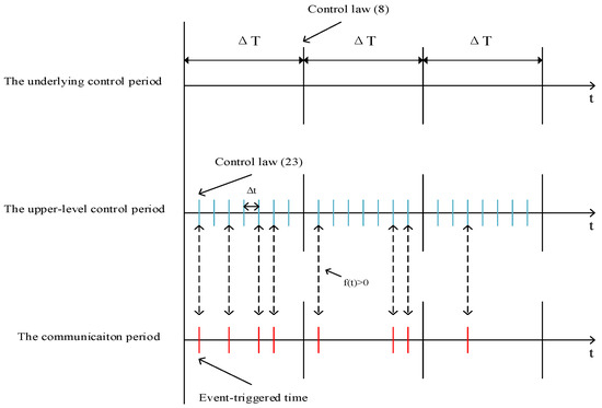
Figure 3.
Sampling Period.
Remark 3.
The parameter qi(0) does not indicate the reactive output value of the PV inverter in the initial state of the system; it represents the result which is obtained by the calculation in Step 1.
6. Simulation Analysis
6.1. Numerical Simulation
This section designs a graph G containing 15 agents. The communication network is shown in Figure 2, and we set the reactive output and capacity of 15 PV inverters as shown in Table 1.

Table 1.
Parameters of distributed PV.
The 15 agents start from the initial conditions and iterate through the distributed control law (10) and event-triggered function (22), setting µ = 0.5, k = 0.5, Ni = 2, B = 15. Its L′ = BC−1L is given by
Figure 4a,b shows that the proportional output of reactive power is achieved with or without the event-triggered distributed control strategy (23). It can be seen from Figure 4a,b that the ratio of reactive power to capacity can converge to the same ratio, whose value is 0.7. These two cases verify the correctness of the convergence problems proposed by Theorems 1 and 2. Meanwhile, the difference between the two methods lies in communication frequency and convergence speed. On the one hand, the convergence rate with ETC is slightly slower than that without ETC. On the other hand, during the 2000 iterations of each agent, 15 agents communicated 7830 times under the event-triggered control. Compared with the non-event-triggered control of full communication, the use of the event-triggered strategy (23) effectively reduces the communication frequency by 74% and saves online communication and computing resources.
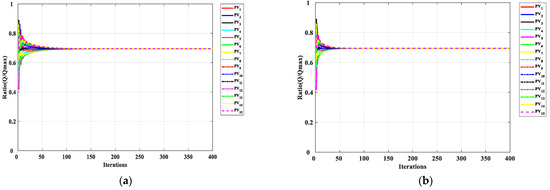
Figure 4.
(a) q/c ratio result with the ETC. (b) q/c ratio result without the ETC.
Although event-triggered control reduces the number of communications, it has an impact on the convergence rate of control law (21). The deviation between the maximum and minimum values of the state quantity x of 15 agents is recorded as E. Figure 5a,b shows the variation of agents’ deviation E with the number of iterations under event-triggered control and non-event-triggered control. When E = xmax − xmin < 0.02, it is considered that reactive power has reached a balanced distribution. Comparing Figure 5a,b, the event-triggered control needs to be iterated to 60 times to achieve reactive power balance, while the non-event-triggered situation only needs to iterate to 30 times to achieve convergence. Event-triggered control reduces the communication frequency while also delaying the convergence speed of the distributed control law. A part of the event-triggered timing of agent1–agent5 is shown in Figure 6.

Figure 5.
(a) E(I) with the ETC. (b) E(I) without the ETC.
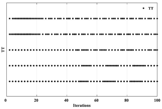
Figure 6.
A part of the event-triggered timing (TT) of agent 1–agent 5. From top to bottom are agents 1, 2, 3, 4, 5.
6.2. Case Studies from Real LVDN
A real-time digital simulator (OPAL-RT OP5600) was used to establish a low-voltage distribution network system with a high proportion of distributed PV, which comes from Wu Xi county Chongqing, China. The simulation model was downloaded to OP5600, and OP5600 conducted the digital simulation in real-time. All of the simulation was carried out digitally. The LVDN consists of 15 sets of PV and loads. The model consists of main grid, transmission lines, PV inverters, and power consumers as shown in Figure 7.
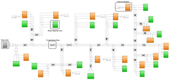
Figure 7.
The simulation model with 15 PV inverters (green module) and loads (orange module).
Distributed generations PV_1–PV_15 work in the maximum power tracking (MPPT) control mode, and DGs export both active and reactive power. Each PV corresponds to a set of loads, and the capacities of PV and loads are listed in Table 2. The nominal voltage amplitude of the system is 380 V, while the frequency is 50 Hz. The transmission line impedance is 0.3811 + j0.1514 Ω/km, and the line lengths from node 0 to each PV node are listed in Table 3. We assumed that the system works in a steady state at the initial time and control period ΔT = 100 ms, Δt = 10 ms.

Table 2.
Parameters of PV and Load.

Table 3.
Length of the Transmission Line.
6.3. Simulation and Analysis
In this section, two simulation cases were designed to analyze and verify the performance and effectiveness of the distributed voltage control strategy with event-triggered control. Case study 1 analyzed the voltage change of a high-permeability PV access distribution network without reactive power control, case study 2 analyzed the influence of the distributed reactive power control on voltage using the event-triggered strategy, and case study 3 compared the difference between centralized control and distributed control proposed in this paper when agent malfunction occurs.
Case Study 1: Voltage Situation without Voltage Control
In order to significantly reflect the impact of PV access on the system, this case only considered the situation in the daytime, and the simulation period was set from 6:00 to 18:00.
The active output of 15 PV is shown in Figure 8. The active power is small in the morning and evening, no higher than 30 kW before 8:00 and after 16:00, and the peak value of the active output appears between 12:00 to 14:00, up to 46 kW.
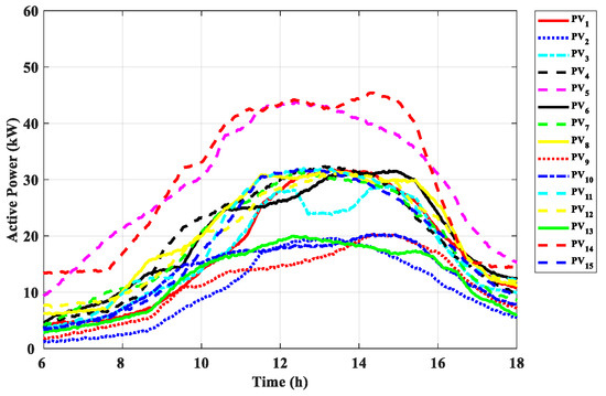
Figure 8.
The active output of PV.
Figure 9 shows the voltage waveform without the voltage control. PV_2 to PV_15 exceed the voltage limit, and the voltage in PV_10 and PV_11 have the most serious violations, up to 1.12 p.u. It can be concluded that the PV output is proportional to the voltage. In addition, the most serious limit violations happen in the farthest nodes. This result is also consistent with the voltage sensitivity analysis.
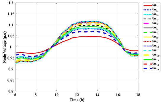
Figure 9.
The voltage of the PV nodes without voltage control.
Case Study 2: Voltage Control Based on the Event-Triggered Strategy
This case study used the aforementioned distributed control method based on the event-triggered strategy.
The network structure and its parameters are given in Figure 7 and Table 2 and Table 3, and the sensitivity coefficient KSQ and weight matrix W in the control law can be calculated using Equations (8) and (10).
During the simulation, before 10:00, the consumption of power increased, and the output of PV was small, so the voltage was close to the lower limit. At this time, according to the control law (8), the PV adjusted the reactive output to compensate for the load demand, so that the voltage stabilized above 0.95 p.u. Between 10:00 and 14:00, the PV output gradually reached its peak, and the load demand was not high enough to completely consume the power provided by the sources. In this case, the PV absorbed the reactive power according to (7), so that the voltage was stabilized below 1.05 p.u. Figure 10 shows the effect of the distributed voltage control, and the voltage of each node is between 0.95–1.05 p.u.
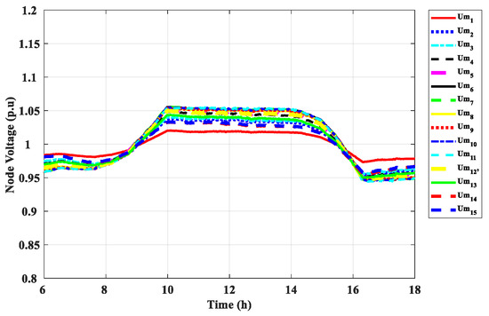
Figure 10.
The voltage of the PV nodes with voltage control.
Figure 11 shows that when the voltage is about to exceed the limit, due to the control law (8) and (23), the PV inverter will choose to compensate or absorb reactive power based on the actual situation of each node, and its compensation or absorption capacity matches the maximum reactive capacity. The ratio Q/C is shown in Figure 12. The Q/C ratios of each PV are nearly equal from 6:00 to 18:00. We thus conclude that the control strategy in this paper is effective.
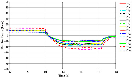
Figure 11.
The reactive output of PV with voltage control.
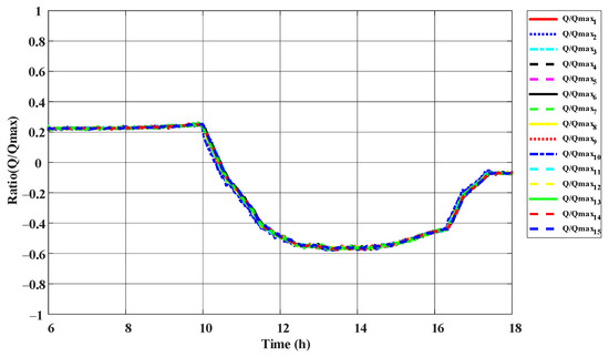
Figure 12.
The q/c ratio of the PV with voltage control.
Case Study 3: Agent Malfunction
In order to reflect the advantages of the distributed control proposed in this paper over centralized control, we compared the voltage situation of the two strategies when agent malfunction occurs in this case study. Centralized control uses the central controller to collect the information of each node and issue instructions to control the DG; when the central agent is malfunctioning, the control purpose cannot be achieved. Figure 13 shows the voltage situation with centralized control when the central agent is malfunctioning. The voltage waveform is the same as Figure 9. Therefore, the system reliability is insufficient, which is also the defect of centralized control.
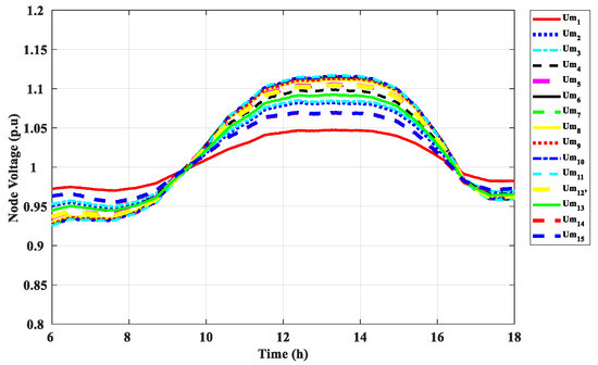
Figure 13.
The voltage situation with centralized control when the central agent malfunctions.
By contrast, the voltage situation with distributed control as proposed in this paper is shown in Figure 14. When agent 8 is malfunctioning, the voltage control in agent 8 is not well-implemented. But the voltage of other nodes is controlled within a reasonable range, because other agents only rely on the information of themselves and of neighbor nodes as criteria for control.
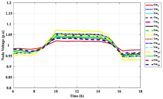
Figure 14.
The voltage situation with distributed control when agent 8 malfunctions.
7. Conclusions
We proposed a sensitivity matrix based distributed event-triggered control model for the voltage control, where each PV inverter adjusts the reactive output to manage the node voltage and attains a balanced distribution of the reactive power. First, we analyzed the MAS model of the control strategy. We then introduced an underlying distributed control method based on the reactive power sensitivity matrix and proposed an upper level event-triggered consistency strategy. We designed the ETC function and introduced a method for choosing parameters for ETC function coefficients.
The 27-node model with 15 PV was built on an OPAL-RT platform to verify the proposed control strategy. Numerical simulation validated that the ETC function can reduce the communication between agents, but it will delay the convergence speed. Three cases were studied by simulation, which compared the voltage waveform with and without the voltage control, and compared it with centralized control in the face of agent malfunction. The method proposed in this paper can effectively stabilize each PV node within a reasonable voltage range, guarantee that the q(t)/c(t) ratio meets the consistency requirement, and effectively reduce the number of control tasks executed, thereby significantly saving communication resources on the basis of ensuring system performance.
To summarize, this paper solves the problems of continuous communication in the MAS system, the high complexity in designing distributed ETCs, and the limitations of system dynamics. Our future research direction is to design distributed control models for other systems, such as small hydropower stations and wind-powered solutions with event-triggered control strategies.
Author Contributions
Conceptualization, Y.L.; methodology, Y.L.; software, M.C.; validation, Y.L., W.K. and M.C.; formal analysis, Y.L.; writing—original draft preparation, Y.L.; writing—review and editing, Y.L.; supervision, M.C. and X.S. All authors have read and agreed to the published version of the manuscript.
Funding
This research received no external funding.
Institutional Review Board Statement
Not applicable.
Informed Consent Statement
Not applicable.
Data Availability Statement
The data presented in this study are available on request from the corresponding author. The data are not publicly available due to they come from Wuxi County in Chongqing, China.
Conflicts of Interest
The authors declare no conflict of interest.
References
- Chandraratne, C.; Naayagi, R.T.; Logenthiran, T.; Panda, G. Adaptive Protection for Microgrid with Distributed Energy Resources. Electronics 2020, 9, 1959. [Google Scholar] [CrossRef]
- Li, B.; Ma, Z.; Hidalgo-Gonzalez, P.; Lathem, A.; Fedorova, N.; He, G.; Zhong, H.; Chen, M.; Kammen, D.M. Modeling the impact of EVs in the Chinese power system: Pathways for implementing emissions reduction commitments in the power and transportation sectors. Energy Policy 2021, 149, 111962. [Google Scholar] [CrossRef]
- Agalgaonkar, Y.; Pal, B.C.; Jabr, R.A. Distribution voltage control considering the impact of PV generation on tap changers and autonomous regulators. In Proceedings of the 2014 IEEE PES General Meeting|Conference & Exposition, National Harbor, MD, USA, 1 January 2014; pp. 182–192. [Google Scholar]
- Yao, S.; Li, C.; Teng, Y.; Yang, X.; Ren, J. Research on Reactive Power and Voltage Optimization Control Method Based on Active Distribution Network. In Proceedings of the 2016 International Conference on Smart City and Systems Engineering (ICSCSE), Hunan, China, 25–26 November 2016; pp. 435–438. [Google Scholar]
- Brenna, M.; De Berardinis, E.; Carpini, L.D.; Foiadelli, F.; Paulon, P.; Petroni, P.; Sapienza, G.; Scrosati, G. Automatic Distributed Voltage Control Algorithm in Smart Grids Applications. IEEE Trans. Smart Grid 2013, 4, 877–885. [Google Scholar] [CrossRef]
- Bletterie, B.; Kadam, S.; Bolgaryn, R.; Zegers, A. Voltage Control with PV Inverters in Low Voltage Networks—In Depth Analysis of Different Concepts and Parameterization Criteria. IEEE Trans. Power Syst. 2017, 32, 177–185. [Google Scholar] [CrossRef]
- Stetz, T.; Marten, F.; Braun, M. Improved Low Voltage Grid-Integration of Photovoltaic Systems in Germany. IEEE Trans. Sustain. Energy 2013, 4, 534–542. [Google Scholar] [CrossRef]
- Fu, Y.; Wang, F.; Chen, C.; Yang, Z.; Liu, B. New Method of Voltage Control Considering Distribution Network Con-taining Distributed Generation. Proc. CSU-EPSA 2015, 27, 26–31. [Google Scholar]
- Xiao, H.; Pei, W.; Deng, W.; Kong, L. Analysis of the Impact of Distributed Generation on Distribution Network Voltage and Its Optimal Control Strategy. Trans. China Electrotech. Soc. 2016, 31, 203–213. [Google Scholar]
- Xu, Z.; Zhao, B.; Ding, M.; Zhou, J.; Wei, L. Photovoltaic Hosting Ca-pacity Evaluation of Distribution Networks and Inverter Parameters Optimization Based on Node Voltage Sensitivity. Proc. CSEE 2016, 36, 1578–1587. [Google Scholar]
- Zhang, J.; Zhuang, H.; Liu, J.; Gao, H.; Zhang, L.; Xia, Y. Two-stage coordi-nated voltage control scheme of active distribution network with voltage support of distributed energy storage system. Electr. Power Autom. Equip. 2019, 39, 15–21. [Google Scholar]
- Moondee, W.; Srirattanawichaikul, W. Study of Coordinated Reactive Power Control for Distribution Grid Voltage Regulation with Photovoltaic Systems. In Proceedings of the 2019 IEEE PES GTD Grand International Conference and Exposition Asia (GTD Asia), Bangkok, Thailand, 19–23 March 2019; pp. 136–141. [Google Scholar]
- Bidram, A.; Davoudi, A.; Lewis, F.L.; Ge, S.S. Distributed Adaptive Voltage Control of Inverter-Based Microgrids. IEEE Trans. Energy Convers. 2014, 29, 862–872. [Google Scholar] [CrossRef]
- Carvalho, P.M.S.; Correia, P.F.; Ferreira, L.A.F.M. Distributed Reactive Power Generation Control for Voltage Rise Mitigation in Distribution Networks. IEEE Trans. Power Syst. 2008, 23, 766–772. [Google Scholar] [CrossRef]
- Wu, X.; Shen, C.; Iravani, R. A Distributed, Cooperative Frequency and Voltage Control for Microgrids. IEEE Trans. Smart Grid 2018, 9, 2764–2776. [Google Scholar] [CrossRef]
- McArthur, S.D.J. Multi-Agent Systems for Power Engineering Applications—Part II: Technologies, Standards, and Tools for Building Multi-agent Systems. IEEE Trans. Power Syst. 2007, 22, 1753–1759. [Google Scholar] [CrossRef]
- Dou, C.; Zhang, Z.; Yue, D.; Zheng, Y. MAS-Based Hierarchical Distributed Coordinate Control Strategy of Virtual Power Source Voltage in Low-Voltage Microgrid. IEEE Access 2017, 5, 11381–11390. [Google Scholar] [CrossRef]
- Wang, X.; Xu, T.; Li, Y. Distributed Voltage Control in Active Distribution Networks Utilizing Multiple Agent System. Proc. CSEE 2016, 36, 2918–2926. [Google Scholar]
- Åström, K.J.; Bernhardsson, B. Comparison of periodic and event based sampling for first-order stochastic systems. IFAC Proc. Vol. 1999, 32, 301–306. [Google Scholar] [CrossRef]
- Åarzén, K.E. A simple event-based PID controller. IFAC Proc. Vol. 1999, 18, 423–428. [Google Scholar] [CrossRef]
- Wang, S.; Fan, Y. On event-triggered algorithm design for distributed coordination of multi-agent systems. In Proceedings of the 26th Chinese Control and Decision Conference (2014 CCDC), Changsha, China, 31 May–2 June 2014; pp. 4951–4957. [Google Scholar]
- Zhu, Y.; Guan, X.; Luo, X.; Li, S. Finite-time consensus of multi-agent system via nonlinear event-triggered control strategy. IET Control Theory Appl. 2015, 9, 2548–2552. [Google Scholar] [CrossRef]
- Dimarogonas, D.V.; Frazzoli, E. Distributed event-triggered control strategies for multi-agent systems. In Proceedings of the 2009 47th Annual Allerton Conference on Communication, Control, and Computing (Allerton), Monticello, IL, USA, 30 September–2 October 2009; pp. 906–910. [Google Scholar]
- Wang, H.; Yu, M.; Xie, G.; Shi, H. Event-triggered circle formation control of multi-agent systems. In Proceedings of the 33rd Chinese Control Conference, Nanjing, China, 28–30 July 2014; pp. 1321–1326. [Google Scholar]
- Nowzari, C.; Cortés, J. Distributed event-triggered coordination for average consensus on weight-balanced digraphs. Automatica 2016, 68, 237–244. [Google Scholar] [CrossRef]
- Rajendar, G.; Banakara, B. Improvement of voltage stability by optimal capacitor placement using sensitivity matrix. In Proceedings of the 2016 International Conference on Signal Processing, Communication, Power and Embedded System (SCOPES), Paralakhemundi, India, 3–5 October 2016; pp. 1991–1996. [Google Scholar]
- Xu, Y.; Liu, W. Novel Multiagent Based Load Restoration Algorithm for Microgrids. IEEE Trans. Smart Grid 2011, 2, 152–161. [Google Scholar] [CrossRef]
- Tabuada, P. Event-Triggered Real-Time Scheduling of Stabilizing Control Tasks. IEEE Trans. Autom. Control 2007, 52, 1680–1685. [Google Scholar] [CrossRef]
Publisher’s Note: MDPI stays neutral with regard to jurisdictional claims in published maps and institutional affiliations. |
© 2021 by the authors. Licensee MDPI, Basel, Switzerland. This article is an open access article distributed under the terms and conditions of the Creative Commons Attribution (CC BY) license (http://creativecommons.org/licenses/by/4.0/).