
Development of C-Shaped Parasitic MIMO Antennas for Mutual Coupling Reduction

 , ,
, ,  ,
,
Abstract
:1. Introduction
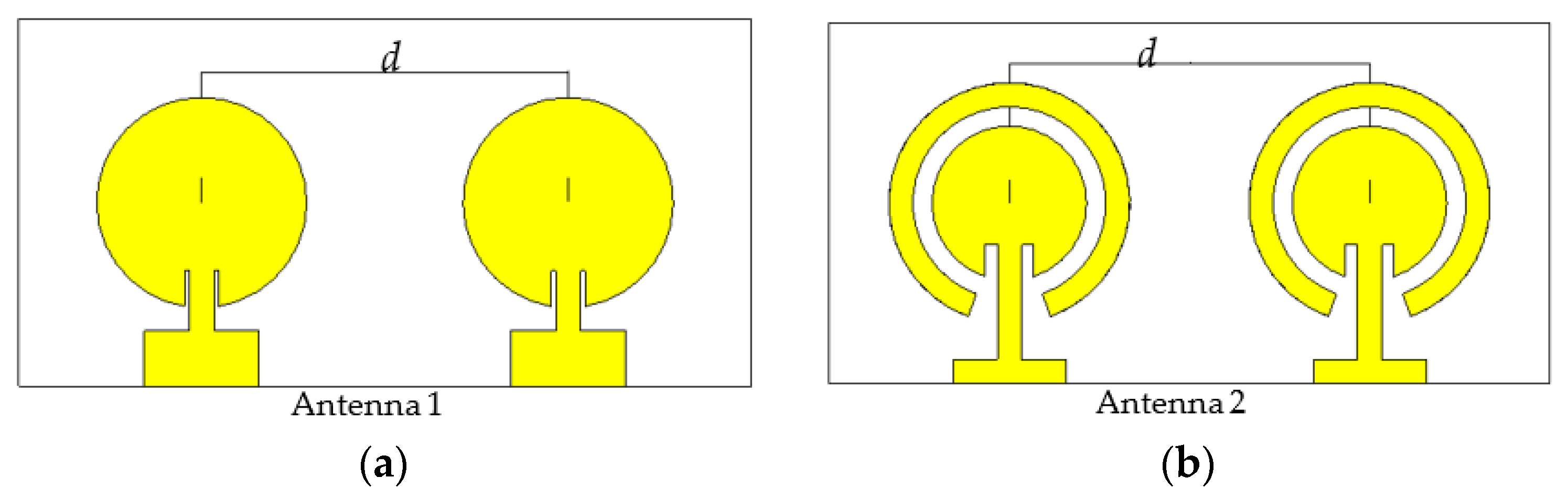
2. Antenna Design and Parasitic Element
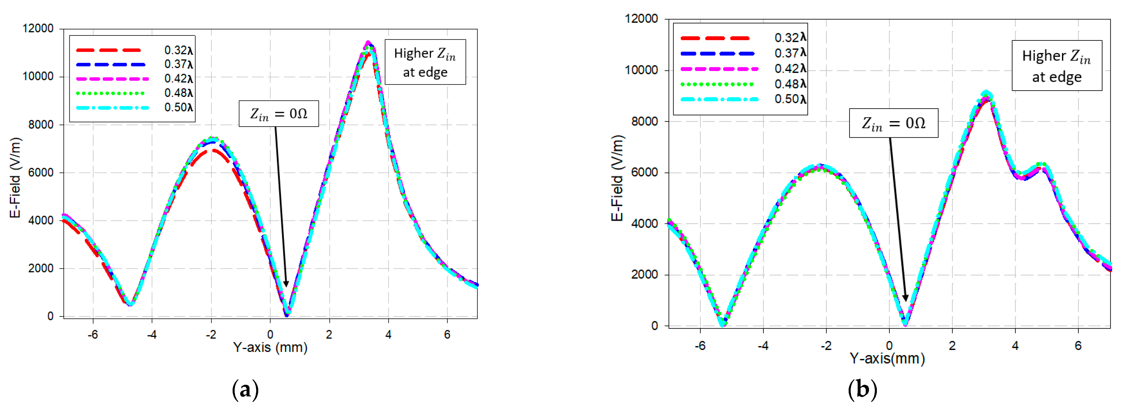
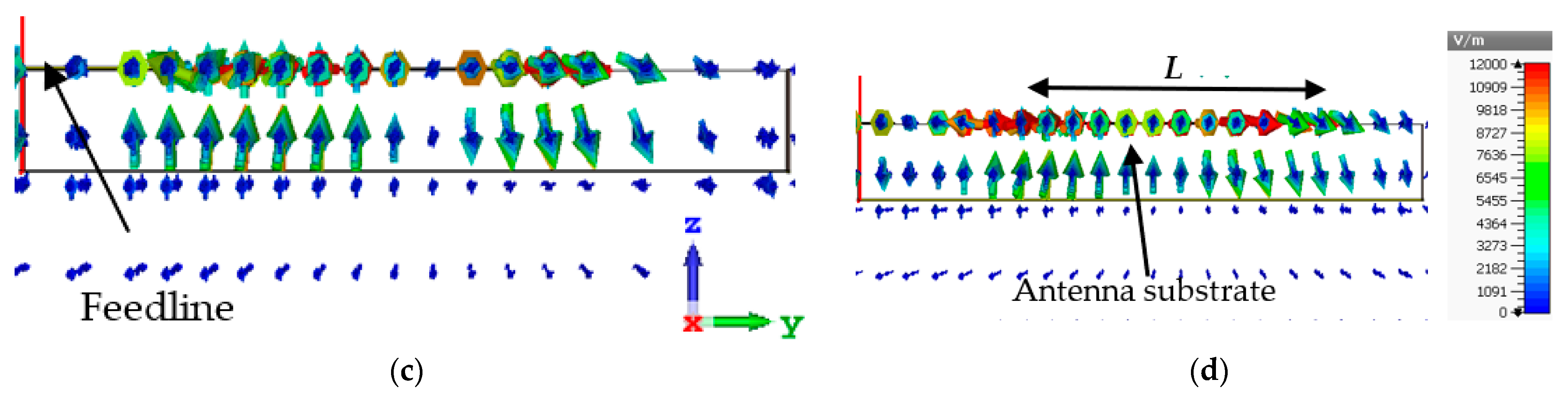
2.1. Observation of Electric Field Intensities along Antenna Edges
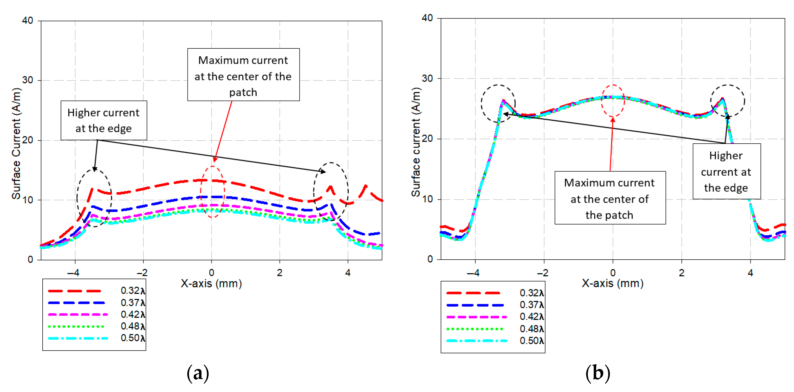
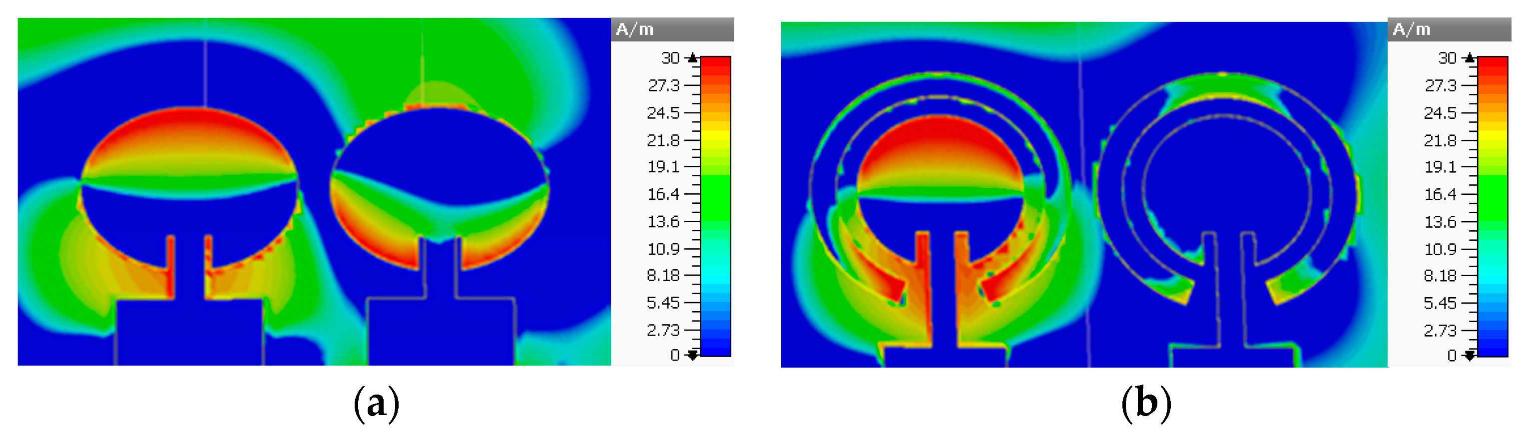
2.2. Observation of Surface Currents
3. Measurement Results and Analysis
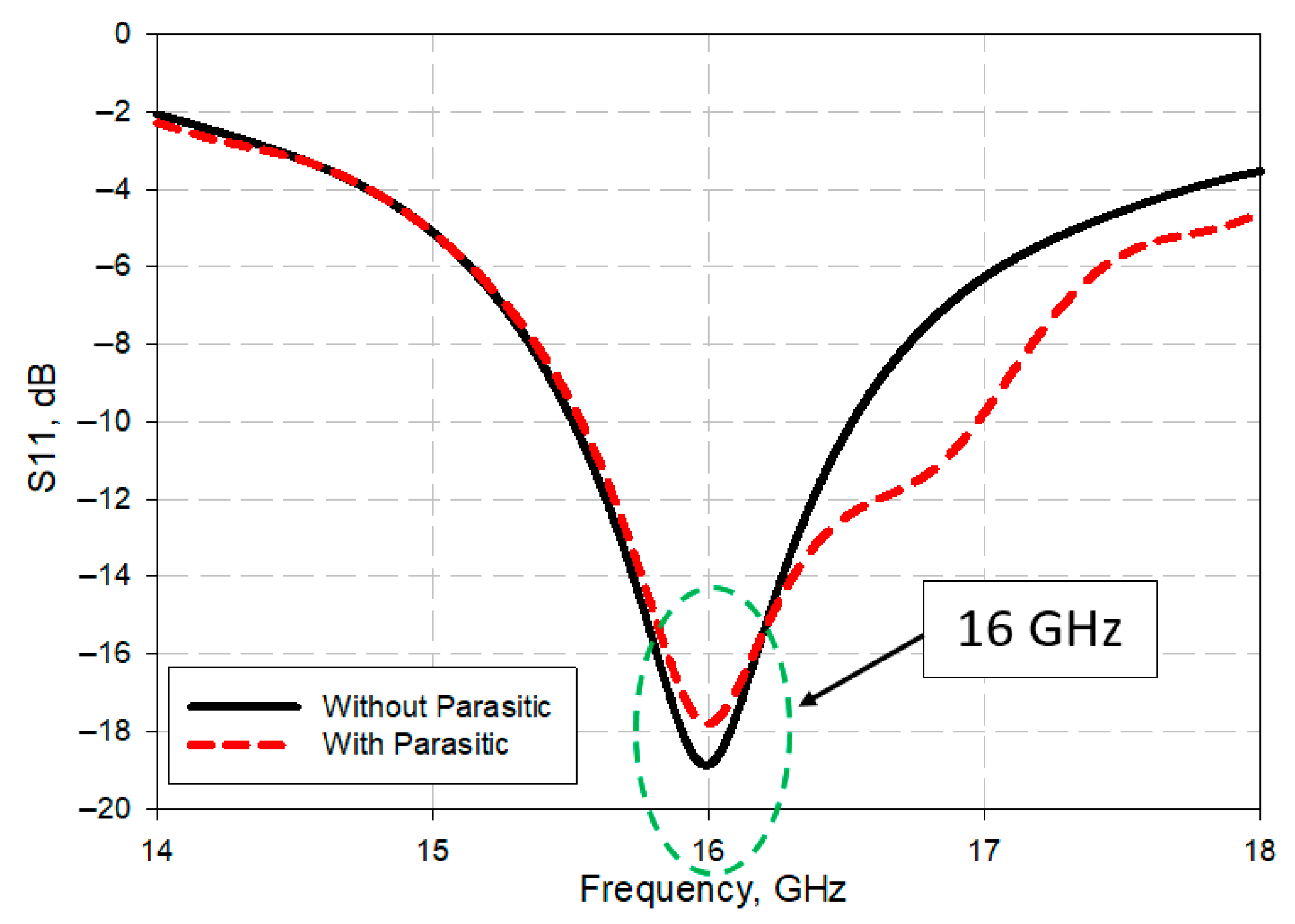
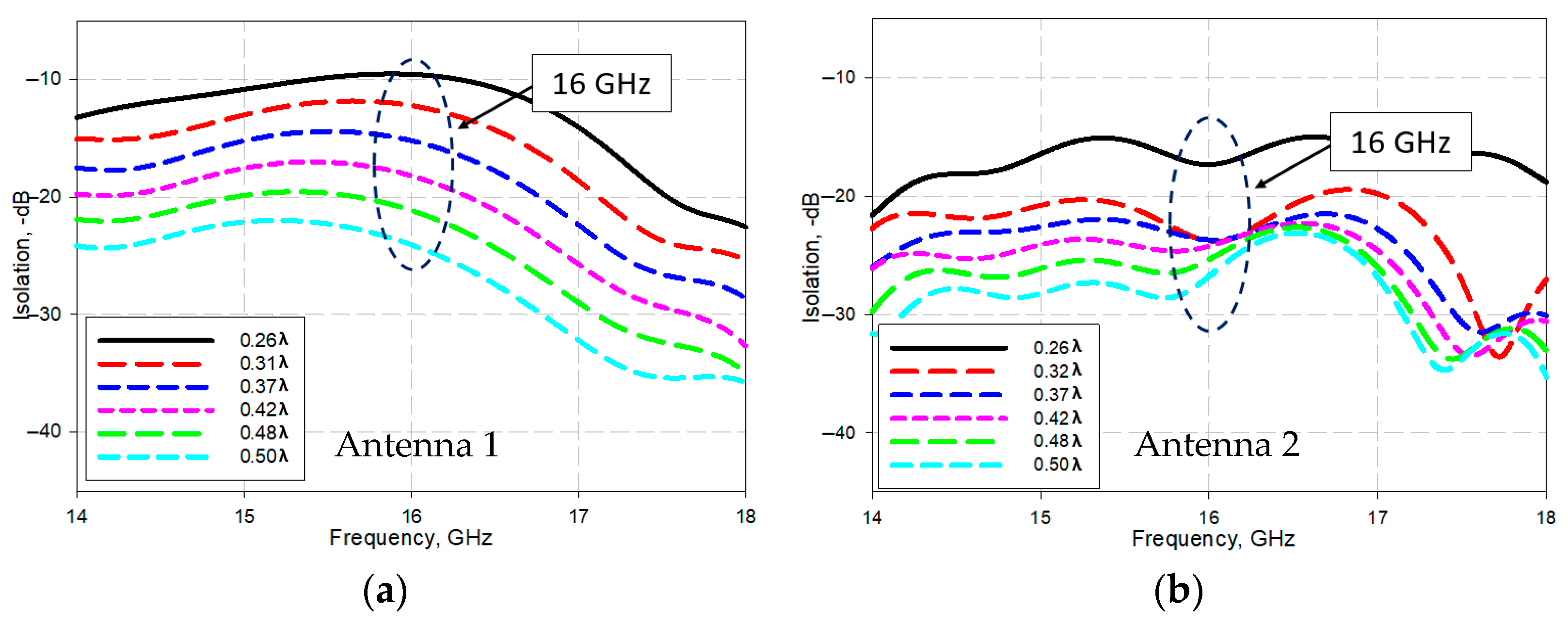
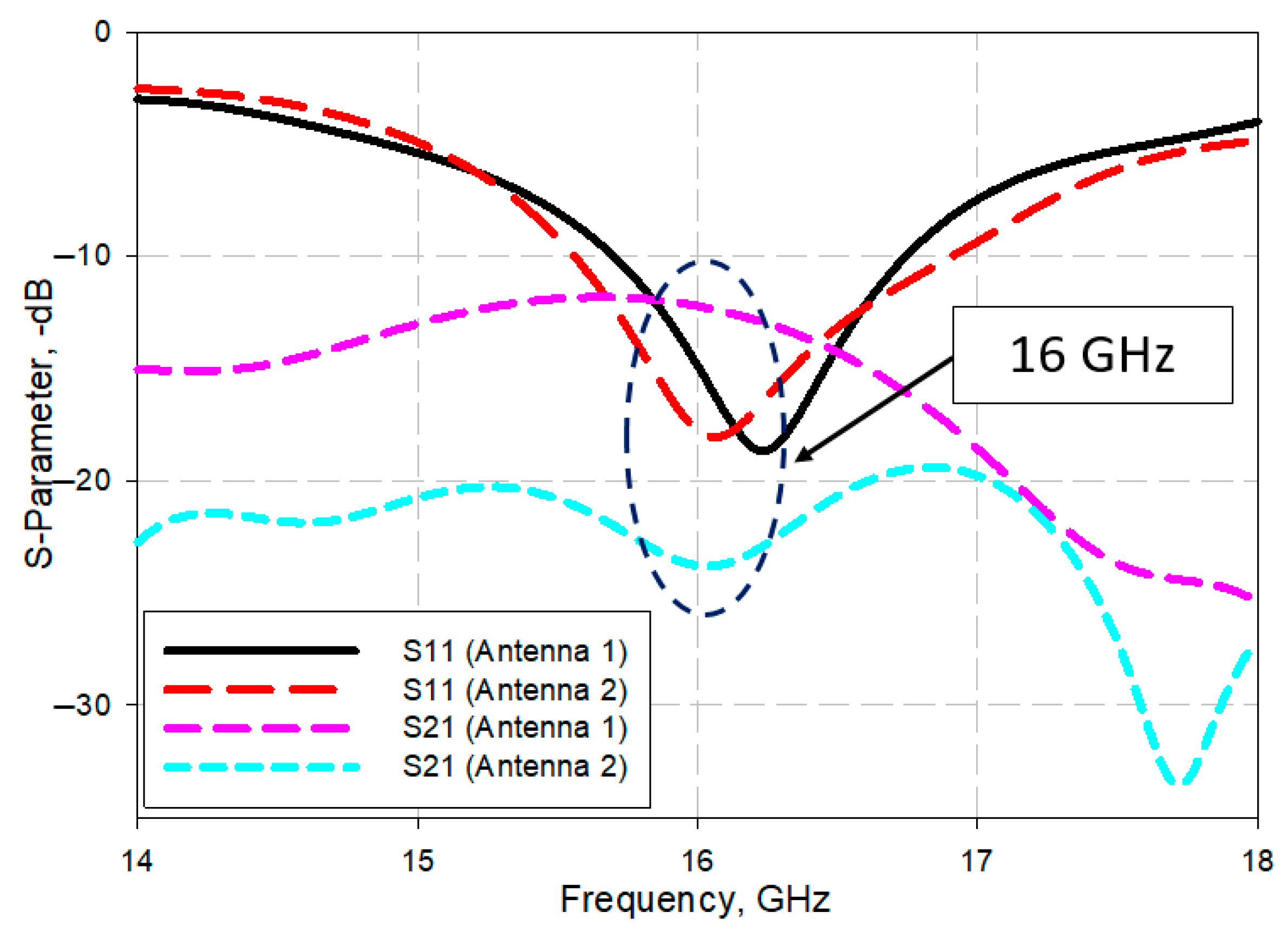
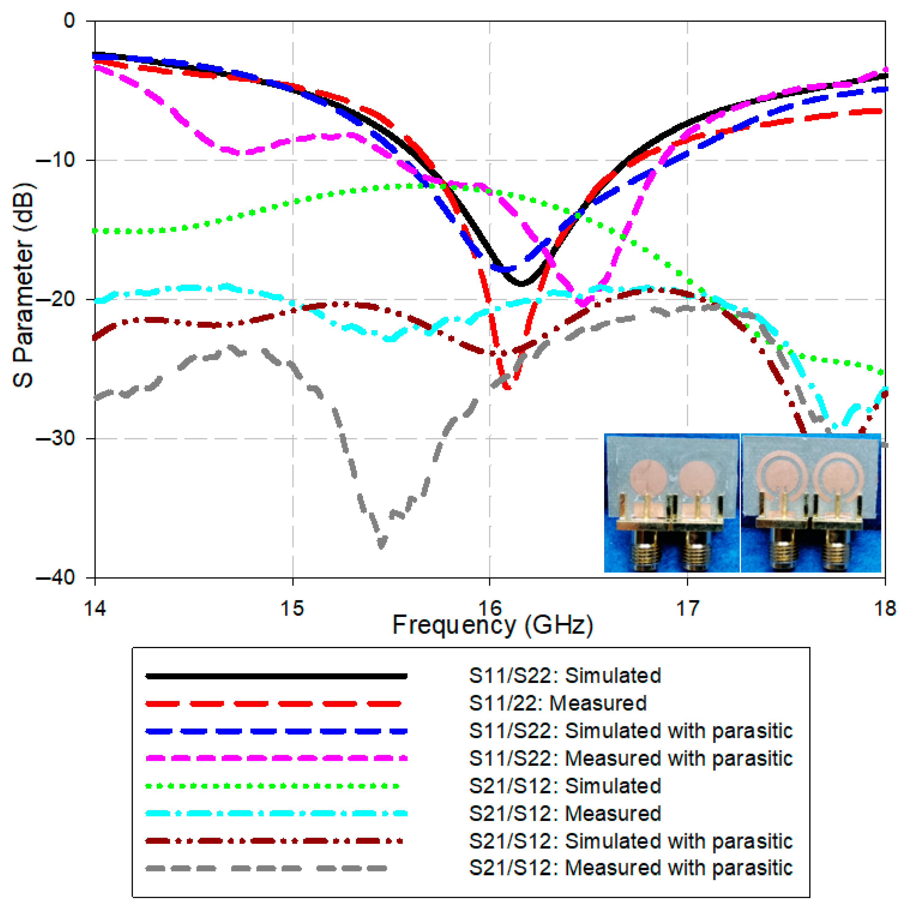
3.1. Return Loss and Isolation
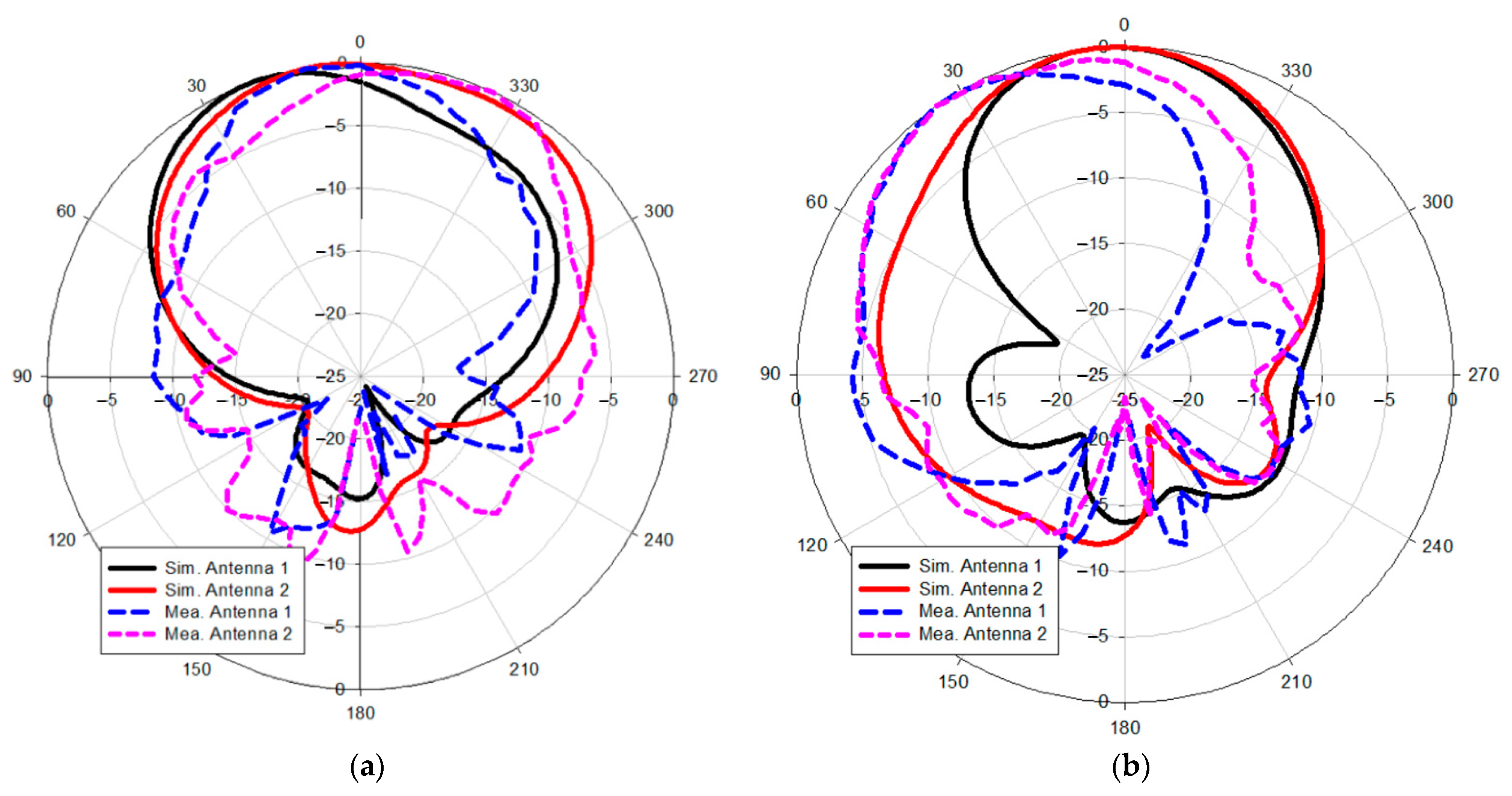
3.2. Radiation Pattern and Antenna Gain
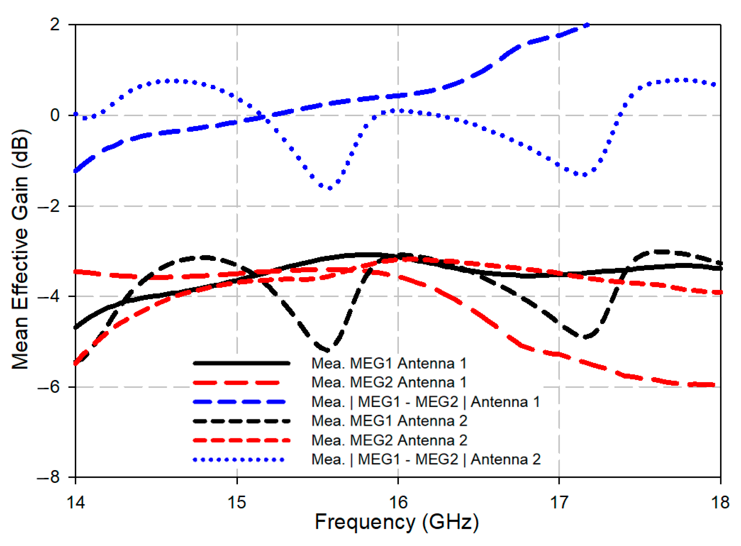
3.3. MIMO Performance Analysis
4. Conclusions
Author Contributions
Funding
Acknowledgments
Conflicts of Interest
References
- Nedil, M. Coupling Reduction between Dipole Antennas. IEEE Antennas Propag. Mag. 2016, 16, 3–4. [Google Scholar]
- Qian, K.; Zhao, L. An Integrated Antenna Interference Cancellation Chip with Frequency Rejection Characteristic for MIMO Systems. IEEE Antennas Wirel. Propag. Lett. 2017, 16, 1285–1288. [Google Scholar] [CrossRef]
- Alibakhshikenari, M. A Comprehensive Survey on “Various Decoupling Mechanisms with Focus on Metamaterial and Metasurface Principles Applicable to SAR and MIMO Antenna Systems”. IEEE Access 2020, 8, 1. [Google Scholar] [CrossRef]
- Parchin, N.O.; Al-yasir, Y.I.A. Eight-Element Dual-Polarized MIMO Slot Antenna System for 5G Smartphone Applications. IEEE Access 2020, 7, 15612–15622. [Google Scholar] [CrossRef]
- Suriya, I.; Anbazhagan, R. Inverted-A based UWB MIMO antenna with triple-band notch and improved isolation for WBAN applications. AEU-Int. J. Electron. Commun. 2019, 99, 25–33. [Google Scholar] [CrossRef]
- Malathi, A.C.J.; Thiripurasundari, D. Review on Isolation Techniques in MIMO Antenna Systems. Indian J. Sci. Technol. 2016, 9, 1–10. [Google Scholar] [CrossRef]
- Hussain, R.; Alreshaid, A.T.; Podilchak, S.K.; Sharawi, M.S. Compact 4G MIMO antenna integrated with a 5G array for current and future mobile handsets. IET Microw. Antennas Propag. 2016, 11, 271–279. [Google Scholar] [CrossRef] [Green Version]
- Cheung, S.W.; Li, Q.; Wu, D.; Zhou, C.; Wang, B. Defected Ground Structure with Two Resonances for Decoupling of Dual-band MIMO Antenna. IEEE Antennas Wirel. Propag. Lett. 2017, 1645–1646. [Google Scholar] [CrossRef]
- Zhu, X.; Yang, X.; Song, Q.; Lui, B. Compact UWB-MIMO antenna with metamaterial FSS decoupling structure. EURASIP J. Wirel. Commun. Netw. 2017, 2017, 115. [Google Scholar] [CrossRef]
- Panda, P.K.; Ghosh, D. Isolation and gain enhancement of patch antennas using EMNZ superstrate. AEU-Int. J. Electron. Commun. 2018, 86, 164–170. [Google Scholar] [CrossRef]
- Pan, B.C.; Tang, W.X.; Qi, M.Q.; Ma, H.F.; Tao, Z.; Cui, T.J. Reduction of the spatially mutual coupling between dual-polarized patch antennas using coupled metamaterial slabs. Sci. Rep. 2016, 6, 30288. [Google Scholar] [CrossRef] [Green Version]
- Chaudharil, A.A. Microstrip MIMO/Diversity Antenna with High Isolation for WLAN Applications. Prog. Electromagn. Res. Symp. 2016, 887–891. [Google Scholar] [CrossRef]
- Lim, S.; Choi, W.C.; Yoon, Y.J.; You, C. An Isolation Technique for Closely Stacked MIMO Antennas. Proc. ISAP 2016, 1, 356–357. [Google Scholar]
- Yon, H.; Rahman, N.H.A.; Aris, M.A.; Jumaat, H. Developed high gain microstrip antenna like microphone structure for 5G application. Int. J. Electr. Comput. Eng. 2020, 10, 3086–3094. [Google Scholar] [CrossRef]
- Yon, H.; Rahman, N.A.; Aris, M.; Jamaluddin, M.; Jumaat, H. Parametric Study on Mutual Coupling Reduction for MIMO Future 5G Antennas. J. Electr. Electron. Syst. Res. 2020, 16, 59–65. [Google Scholar] [CrossRef]
- Yon, H.; Ali, M.T.; Aris, M.A.; Baharom, B.; Nasir, N.A.M. A New Model Microstrip Antenna like Microphone Structure for 5G Application. In Proceedings of the 2018 IEEE International RF and Microwave Conference (RFM), Penang, Malaysia, 17–19 December 2018; pp. 17–20. [Google Scholar]
- Malaysian Communications and Multimedia Commission. Radio Spectrum Allocations in Malaysia; Malaysian Communications and Multimedia Commission: Cyberjaya, Selangor Darul Ehsan, Malaysia, 2017; p. 200.
- Au, T.M.; Luk, K.M. Effect of parasitic element on the charecteristics of microstrip antenna. IEEE Trans. Antennas Propag. 1991, 39, 1247–1251. [Google Scholar] [CrossRef]
- Agrawal, A.; Jain, A. Effect of Directly Coupled Parasitic Patch on Floral Shaped Patch Antenna. Int. J. Eng. Res. Appl. 2012, 2, 954–957. [Google Scholar]
- Garg, R.; Bhartia, P.; Bahl, I.J. Microstrip Antenna Design Handbook; Artech House Publisher: London, UK, 2001. [Google Scholar]
- Anitha, R.; Sarin, V.; Vasudevan, K.; Mohanan, P. Enhanced isolation with defected ground structure in MIMO antenna. Electron. Lett. 2014, 50, 1784–1786. [Google Scholar] [CrossRef]
- Choudhary, A.; Morya, S. A Review Paper on MIMO Antenna Isolation Improving Techniques. J. Int. Shodh Eng. Technol. 2017, 2, 1–5. [Google Scholar]
- Luo, C.; Hong, J.; Zhong, L. Isolation Enhancement of a Very Compact UWB-MIMO Slot Antenna With Two Defected Ground Structures. IEEE Antennas Wirel. Propag. Lett. 2015, 14, 1766–1769. [Google Scholar] [CrossRef]
- Li, G.; Zhai, H.; Ma, Z.; Liang, C.; Yu, R.; Liu, S. Isolation-improved dual-band MIMO antenna array for LTE/WiMAX mobile terminals. IEEE Antennas Wirel. Propag. Lett. 2014, 13, 1128–1131. [Google Scholar]
- Rahman, N.H.A.; Yamada, Y.; Nordin, M.S.A. Analysis on the Effects of the Human Body on the Performance of Electro-Textile Antennas for Wearable Monitoring and Tracking Application. Materials 2019, 12, 1636. [Google Scholar] [CrossRef] [PubMed] [Green Version]
- Matzner, H.; Levy, S. Antenna Gain. Available online: https://www.hit.ac.il/.upload/engineering/antenna_-_exp4gain.pdf (accessed on 28 September 2021).
- Lin, I.K.C.; Jamaluddin, M.H.; Awang, A.; Selvaraju, R.; Dahri, M.H.; Yen, L.C.; Rahim, H.A. A Triple Band Hybrid MIMO Rectangular Dielectric Resonator Antenna for LTE Applications. IEEE Access 2019, 7, 122900–122913. [Google Scholar]
- Manteghi, M.; Rahmat-Samii, Y. Multiport characteristics of a wide-band cavity backed annular patch antenna for multipolarization operations. IEEE Trans. Antennas Propag. 2005, 53, 466–474. [Google Scholar] [CrossRef]
- Sharawi, M.S. Printed MIMO Antenna Engineering; Artech House: London, UK, 2014. [Google Scholar]
- Su, S.-W.; Lee, C.-T.; Chang, F.-S. Printed MIMO-antenna system using neutralization-line technique for wireless USB-dongle applications. IEEE Trans. Antennas Propag. 2012, 60, 456–463. [Google Scholar] [CrossRef]
- Sharawi, M.S. Printed MIMO Antenna Systems: Performance Metrics, Implementations and Challenges. Forum Electromagn. Res. Methods Appl. Technol. 2013, 1, 1–11. [Google Scholar] [CrossRef]
- Wu, Y.; Long, Y. A High Isolation MIMO Antenna without Decoupling Structure for LTE 700 MHz. Hindawi Int. J. Antennas Propag. 2015, 2015, 1–7. [Google Scholar] [CrossRef] [Green Version]
- Blanch, I.C.S.; Romeu, J. Exact representation of antenna system diversity performance from input parameter description. Electron. Lett. 2003, 53, 1689–1699. [Google Scholar]
- Al-Saif, H.; Usman, M.; Chughtai, M.T.; Nasir, J. Compact Ultra-Wide Band MIMO Antenna System for Lower 5G Bands. Wirel. Commun. Mob. Comput. 2018, 2018, 1–6. [Google Scholar] [CrossRef] [Green Version]
- Kildal, P.-S.; Rosengren, K. Electromagnetic analysis of effective and apparent diversity gain of two parallel dipoles. IEEE Antennas Wirel. Propag. Lett. 2003, 2, 9–13. [Google Scholar] [CrossRef]
- Xu, Q.; Huang, Y.; Zhu, X.; Alja’Afreh, S.; Xing, L.; Tian, Z. Diversity Gain Measurement in a Reverberation Chamber Without Extra Antennas. IEEE Antennas Wirel. Propag. Lett. 2015, 14, 1666–1669. [Google Scholar] [CrossRef]
- Sharawi, M.S. Printed multi-band MIMO antenna systems: Techniques and Isolation mechanisms. Eur. Conf. Antennas Propag. 2014, 1, 779–783. [Google Scholar]
- Taga, T. Antennas in Land Mobile Radio. IEEE Trans. Veh. Technol. 1990, 39, 117–131. [Google Scholar] [CrossRef]
- Nielsen, J.Ø.; Pedersen, G.F.; Olesen, K.; Kovacs, I.Z. Computation of mean effective gain from 3D measurements. In Proceedings of the 1999 IEEE 49th Vehicular Technology Conference, Houston, TX, USA, 16–20 May 1999; Volume 1, pp. 787–791. [Google Scholar]
- Zou, L.; Abbott, D.; Fumeaux, C. Omnidirectional cylindrical dielectric resonator antenna with dual polarization. IEEE Antennas Wirel. Propag. Lett. 2012, 11, 515–518. [Google Scholar] [CrossRef] [Green Version]
- Wani, Z.; Abegaonkar, M.P.; Koul, S.K. A 28-GHz antenna for 5G MIMO applications. Prog. Electromagn. Res. Lett. 2018, 78, 73–79. [Google Scholar] [CrossRef] [Green Version]
- Tu, D.T.T.; Thang, N.G.; Ngoc, N.T.; Phuong, N.T.B.; Van Yem, V. 28/38 GHz Dual-Band MIMO Antenna with Low Mutual Coupling using Novel Round Patch EBG Cell for 5G Applications. In Proceedings of the 2017 International Conference on Advanced Technologies for Communications (ATC), Quynhon City, Vietnam, 18–20 October 2017; pp. 64–69. [Google Scholar]
- Alibakhshikenari, M.; Khalily, M.; Virdee, B.S.; See, C.H.; Abd-Alhameed, R.A.; Limiti, E. Mutual Coupling Suppression Between Two Closely Placed Microstrip Patches Using EM-Bandgap Metamaterial Fractal Loading. IEEE Access 2019, 7, 23606–23614. [Google Scholar] [CrossRef]
- Kayabasi, A.; Toktas, A.; Yigit, E.; Sabanci, K. Triangular quad-port multi-polarized UWB MIMO antenna with enhanced isolation using neutralization ring. AEU-Int. J. Electron. Commun. 2018, 85, 47–53. [Google Scholar] [CrossRef]
- Wang, F.; Duan, Z.; Li, Q.; Wei, Y.; Gong, Y. Compact Wideband MIMO Antenna for 5G Communication. In Proceedings of the 2017 IEEE International Symposium on Antennas and Propagation & USNC/URSI National Radio Science Meeting, Boston, MA, USA, 8–13 July 2018; pp. 939–940. [Google Scholar]
- Mathur, R.; Dwari, S. Compact CPW-Fed ultrawideband MIMO antenna using hexagonal ring monopole antenna elements. AEU-Int. J. Electron. Commun. 2018, 93, 1–6. [Google Scholar]


| Parameters | Without Parasitic | With Parasitic |
|---|---|---|
| Frequency (GHz) | 16 | 16 |
| Gain (dBi) | 7.98 | 7.69 |
| Reflection coefficient (dB) | −18.74 | −17.98 |
| Efficiency (%) | 80.09 | 81.07 |
| VSWR | 1.2614 | 1.2892 |
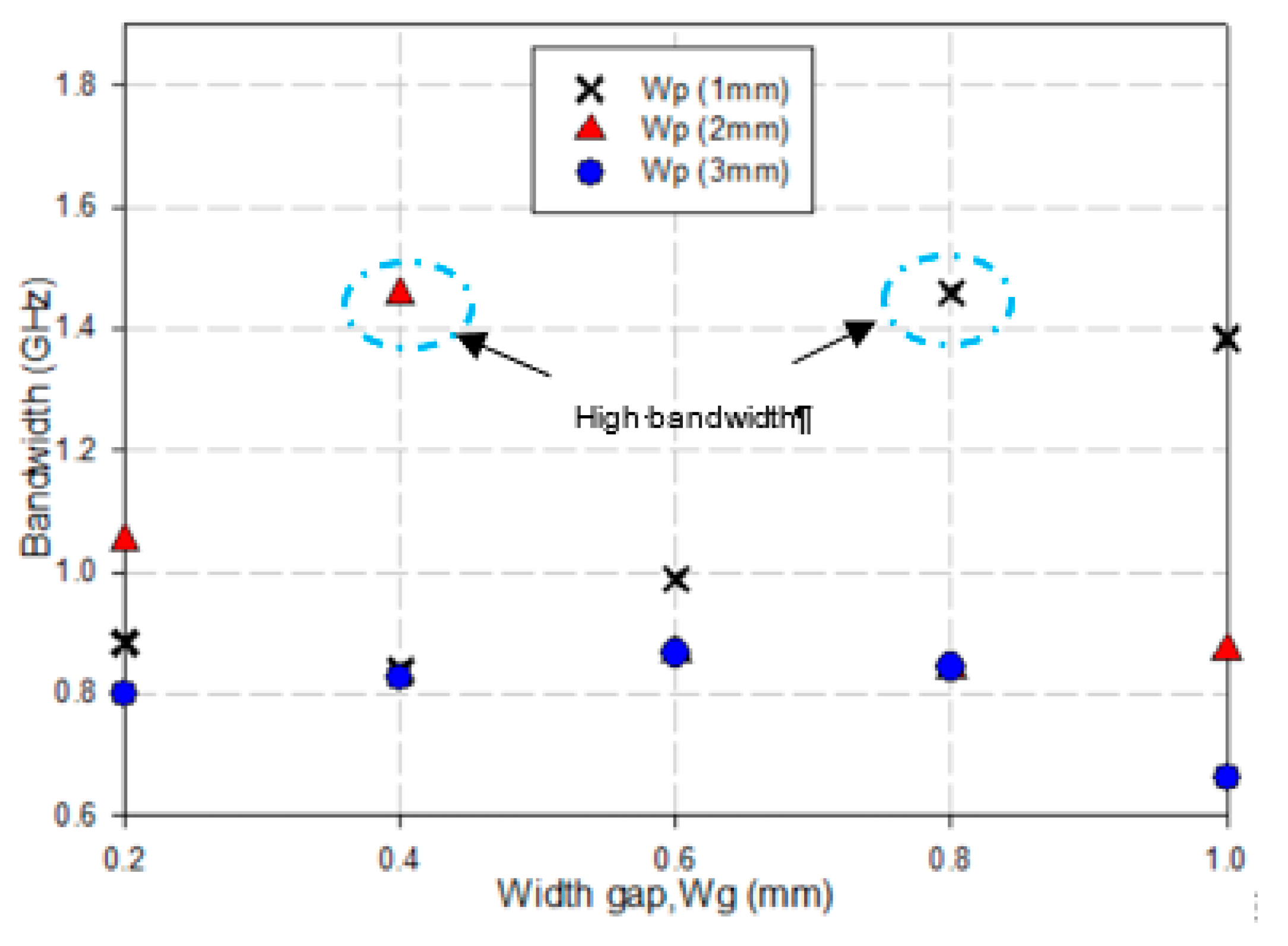
| Bandwidth (MHz) | 913 | 1459 |
| Parameters | Value (mm) |
|---|---|
| Diameter of patch (Dp) | 3.22 |
| Distance between element (d) | 0.32λ |
| Length of feed (Lf) | 2 |
| Length of substrate (Ls) | 15 |
| Material thickness (Hs) | 1.57 |
| Width of parasitic element (Wp) | 1 |
| Width of feed (Wf) | 4.77 |
| Width parasitic (Wp) | 1 |
| Width of substrate (Ws) | 26 |
| Width gap (Wg) | 0.8 |
| Cite | Size (mm²) | Bandwidth (GHz) | Isolation (dB) | TARC (dB) | ECC (dB) | Diversity Gain (dB) | MEG (dB) |
|---|---|---|---|---|---|---|---|
| [41] | 2.89λ × 1.03λ | 26 to 31 | >−21 | - | 0.15 | - | - |
| [42] | 1.77λ × 2.42λ | 28 to 28.5 | >−25 | - | - | - | - |
| [43] | 5.6λ × 2.96λ | 15.6 to 17.1 | >−20 | - | - | - | - |
| [44] | 2.5λ × 2.5λ | 3.1 to 17.3 | >−15 | - | 0.1 | - | - |
| [45] | 1.13λ × 1.13λ | 3 to 30 | >−20 | - | - | - | - |
| [46] | 0.9λ × 0.5λ | 3 to 12 | >−20 | - | 0.2 | - | - |
| Proposed | 0.8λ × 1.33λ | 15.5 to 17 | >−30 | Yes | 0.14 | 9.89 | 0.351 |
Publisher’s Note: MDPI stays neutral with regard to jurisdictional claims in published maps and institutional affiliations. |
© 2021 by the authors. Licensee MDPI, Basel, Switzerland. This article is an open access article distributed under the terms and conditions of the Creative Commons Attribution (CC BY) license (https://creativecommons.org/licenses/by/4.0/).
Share and Cite
Yon, H.; Rahman, N.H.A.; Aris, M.A.; Jamaluddin, M.H.; Kong Cheh Lin, I.; Jumaat, H.; Mohd Redzwan, F.N.; Yamada, Y. Development of C-Shaped Parasitic MIMO Antennas for Mutual Coupling Reduction. Electronics 2021, 10, 2431. https://doi.org/10.3390/electronics10192431
Yon H, Rahman NHA, Aris MA, Jamaluddin MH, Kong Cheh Lin I, Jumaat H, Mohd Redzwan FN, Yamada Y. Development of C-Shaped Parasitic MIMO Antennas for Mutual Coupling Reduction. Electronics. 2021; 10(19):2431. https://doi.org/10.3390/electronics10192431
Chicago/Turabian StyleYon, Hamizan, Nurul Huda Abd Rahman, Mohd Aziz Aris, Mohd Haizal Jamaluddin, Irene Kong Cheh Lin, Hadi Jumaat, Fatimah Nur Mohd Redzwan, and Yoshihide Yamada. 2021. "Development of C-Shaped Parasitic MIMO Antennas for Mutual Coupling Reduction" Electronics 10, no. 19: 2431. https://doi.org/10.3390/electronics10192431
APA StyleYon, H., Rahman, N. H. A., Aris, M. A., Jamaluddin, M. H., Kong Cheh Lin, I., Jumaat, H., Mohd Redzwan, F. N., & Yamada, Y. (2021). Development of C-Shaped Parasitic MIMO Antennas for Mutual Coupling Reduction. Electronics, 10(19), 2431. https://doi.org/10.3390/electronics10192431