Article

Link and System-Level NOMA Simulator: The Reproducibility of Research

1
Electrical and Computer Engineering, COMSATS University Islamabad, Lahore Campus, Lahore 54000, Pakistan
2
Department of IT Convergence Engineering, Kumoh National Institute of Technology, Gumi 39177, Korea
3
Faculty of Science, Engineering and Computing, Kingston University, London KT1 2EE, UK
4
Engineering and Technology, Superior University Lahore, 17 Km Main Raiwind Road Lahore, Lahore 54000, Pakistan
*
Author to whom correspondence should be addressed.
Electronics 2021, 10(19), 2388; https://doi.org/10.3390/electronics10192388
Submission received: 6 August 2021 / Revised: 23 September 2021 / Accepted: 26 September 2021 / Published: 30 September 2021
(This article belongs to the Section Microwave and Wireless Communications)

Abstract

:
This study focuses on the design of a MATLAB platform for non-orthogonal multiple access (NOMA) based systems with link-level and system-level analyses. Among the different potential candidates for 5G, NOMA is gaining considerable attention owing to the many-fold increase in spectral efficiency as compared to orthogonal multiple access (OMA). In this study, a NOMA simulator is presented for two and more than two users in a single cell for link-level analysis; whereas, for system-level analysis, seven cells and 19 cells scenarios were considered. Long-term evolution (LTE) was used as the baseline for the NOMA simulator, while bit error rate (BER), throughput and spectral efficiency are used as performance metrics to analyze the simulator performance. Moreover, we demonstrated the application of the NOMA simulator for different simulation scenarios through examples. In addition, the performance of multi-carrier NOMA (MC-NOMA) was evaluated in the presence of AWGN, impulse noise, and intercell interference. To circumvent channel impairments, channel coding with linear precoding is suggested to improve the BER performance of the system.

1. Introduction

Dependency on mobile wireless communication has increased at enormous rates over the past few decades. The rapid increase in the demand for subscribers has posed challenges in terms of improved data rate, low latency, large coverage, and enhanced reliability [1]. Therefore, to satisfy market demands, the research community is focusing on the proposal of new techniques and approaches for the development of 5G mobile networks. These networks are aimed at a three-fold expansion in the spectral efficiency of future systems as compared to existing networks [1]. Several potential candidates have gained the attention of researchers for future radio access (FRA), where new non-orthogonal multiple access (NOMA) schemes have been examined, such as multi-user shared access (MUSA), which uses a special spreading sequence to overlap and transmit the data through the channel [2,3]. Pattern-division multiple access (PDMA) is another type of multiple access scheme that utilizes encoded patterns to multiplex data at the same time, frequency, and spatial resources [4]. Similarly, sparse code multiple access (SCMA) is a non-orthogonal multiple access scheme that is a code-book-based data mapping technique to enhance the sparsity and shaping gain of each layer, where the message passing algorithm is used for multi-user detection [5]. Furthermore, various state-of-the-art techniques related to NOMA have been presented by researchers to explore and analyze the quality of service and successful SIC operation at the receiver side. The full-duplex NOMA system is presented in [6], where researchers have demonstrated improved throughput and energy efficiency by utilizing the cooperative NOMA technique. Multi-subchannel resource allocation was investigated in [7]; to maintain the low complex structure of NOMA and enhance energy efficiency. The purpose of these techniques is to improve the resource allocation, SIC, and interference management process that provide significant gains in terms of bit error rate (BER), energy efficiency and signal detection probability at the receiving end.
The above-mentioned schemes manifest the basic principle of NOMA to multiplex users in the time, frequency, and spatial domains. This article mainly deals with the power domain NOMA (PD-NOMA), which comprises a superposition coding (SC) algorithm to combine the user’s data at the transmitter side and successive interference cancellation (SIC) at the receiver side to recover the data. As the name indicates, NOMA works in a non-orthogonal fashion, where users are multiplexed in the power domain instead of the time or frequency domain. The significance of user multiplexing in the power domain is resource allocation, where users share the entire time/frequency-domain resource block simultaneously. This approach is different from the conventional orthogonal multiple access (OMA) system, where resources are exclusively allocated to one user, and triggers the scarcity of resources for the other users. Although, NOMA has not been standardized, it has been suggested in the 13th release of 3GPP-LTE (A) as multiuser superposition transmission. To meet the demands of future 5G networks, the NOMA technique confirms the improved performance of the system owing to its ability to work on top of other technologies such as multiple-input–multiple-output (MIMO) and distributed antenna systems [8]. Using NOMA on top of such technologies will provide extra frequency reuse gain to further boost performance. The employment of NOMA in combination with beam-forming technologies in the small-cell environment is an intriguing application scenario as well. However, despite the cost of a complex detection procedure, the benefits provided by NOMA on top of these technologies, including optimal resource allocation, higher data rate, and reduced latency, are substantial.
The research conducted herein is specifically related to the development of a simulator for NOMA-based systems. Various simulator-related articles have been presented in the literature [9,10,11,12] where, 4G-LTE-communication-network-lab presented an end-to-end 4G LTE and IMS Network Simulation-Test-Suite (STS) that includes all components such as NodeB, MME, Serving Gateway, and others to allow comprehensive LTE network testing [13]. Similarly, researchers in [12] presented a 4G Planning Tool that is a multi-agent-based mobile traffic simulator (MTS) built with Google Maps and JavaScript programming languages. However, the aforementioned works mainly focus the LTE or 4G standards and lacks the utilization of NOMA as multiple-access technique to support mass connection for 5G and beyond. As a result, to the best of our knowledge, our work is believed to be the first study provided as a software simulation suite related to NOMA. The main objective of this simulator is developing a platform for researchers to reproduce results related to NOMA. Although reproducibility is not an entirely new idea from the perspective of different studies such as mathematics and nature science, it is a relatively new proposal from the signal processing perspective. It deals with the reproduction of different results generally observed in numerous research articles [14,15,16,17,18]. Reproducing results from other papers is no doubt a challenging task because precise information is not shared in the articles for various reasons, such as lack of access to methodological details, suppressed information due to limitations in allowed pages, and under-reporting of undesirable experimental results. However, if a beginner or a cross-domain expat wants to further work on a published article, the omission of such minor details makes it difficult to generate the same results as published in the considered article. This situation becomes more tedious when the authors are unable to generate their expected simulation results [11,19]. Reproducibility is especially important in areas where experimental research has been conducted [20]. The research community related to signal processing is even trying hard to work on the ideas that lead to negative results. Therefore, promoting the publication of negative results where one can discuss what hypothesis needs to be avoided in a particular domain is crucial; this will help freshers avoid repeating the mistakes carried out by others [21].
Therefore, this article presents a better software suite solution for the NOMA technique, where link-level and system-level environments for reproducible research are demonstrated. The main motivation behind the development of the NOMA simulator is to provide a simulation environment to the researchers, specifically for the generation of results that have already been published in the equivalent research article. This particular simulator follows the baseline of long-term evolution (LTE) as the Vienna LTE simulators presented in [20]. The link-level and system-level simulators for NOMA-based systems lead to the following contributions:
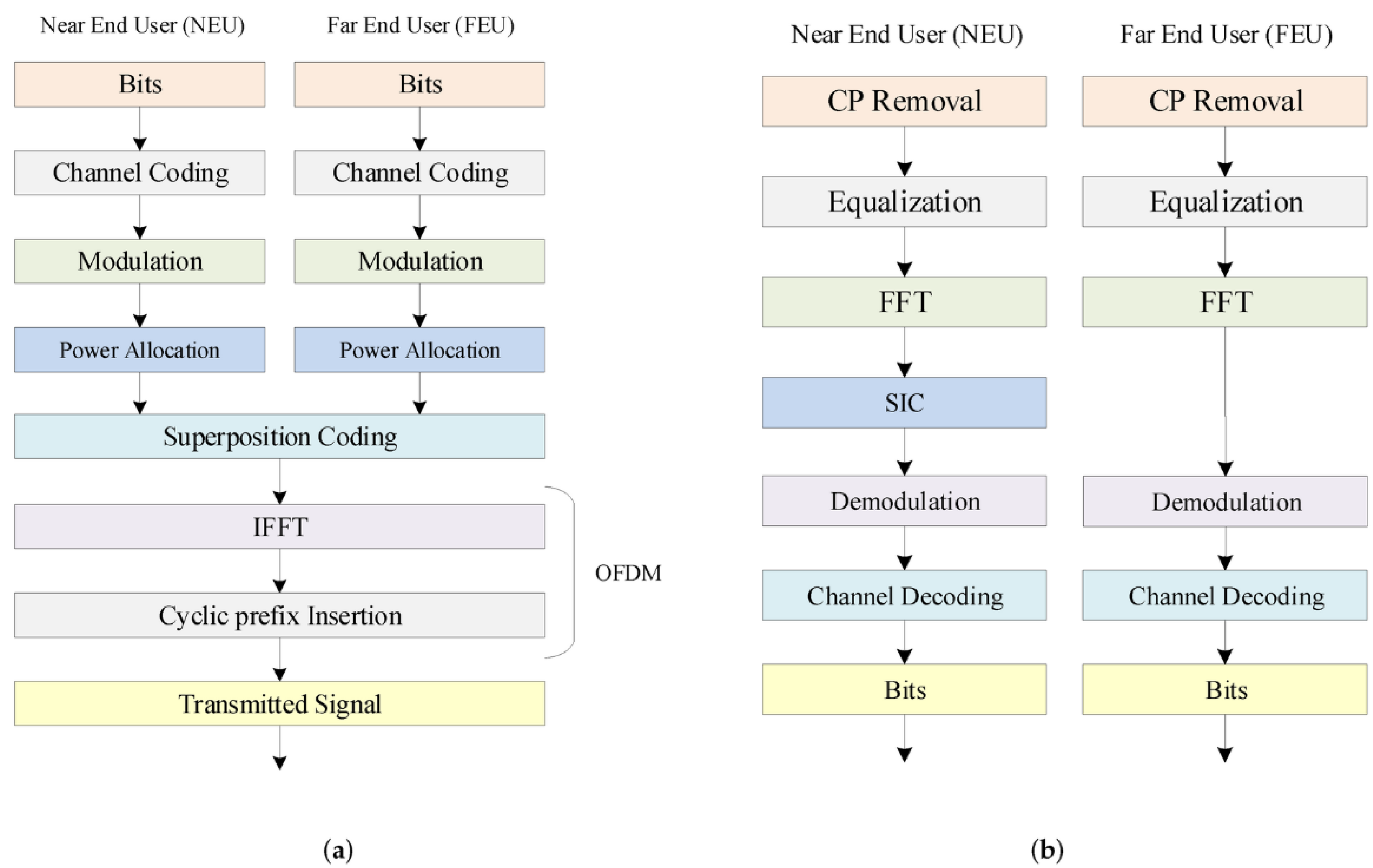
  • It can support both single carrier (SC) and the multi-carrier (MC) downlink NOMA system, which is based on orthogonal frequency division multiplexing (OFDM).
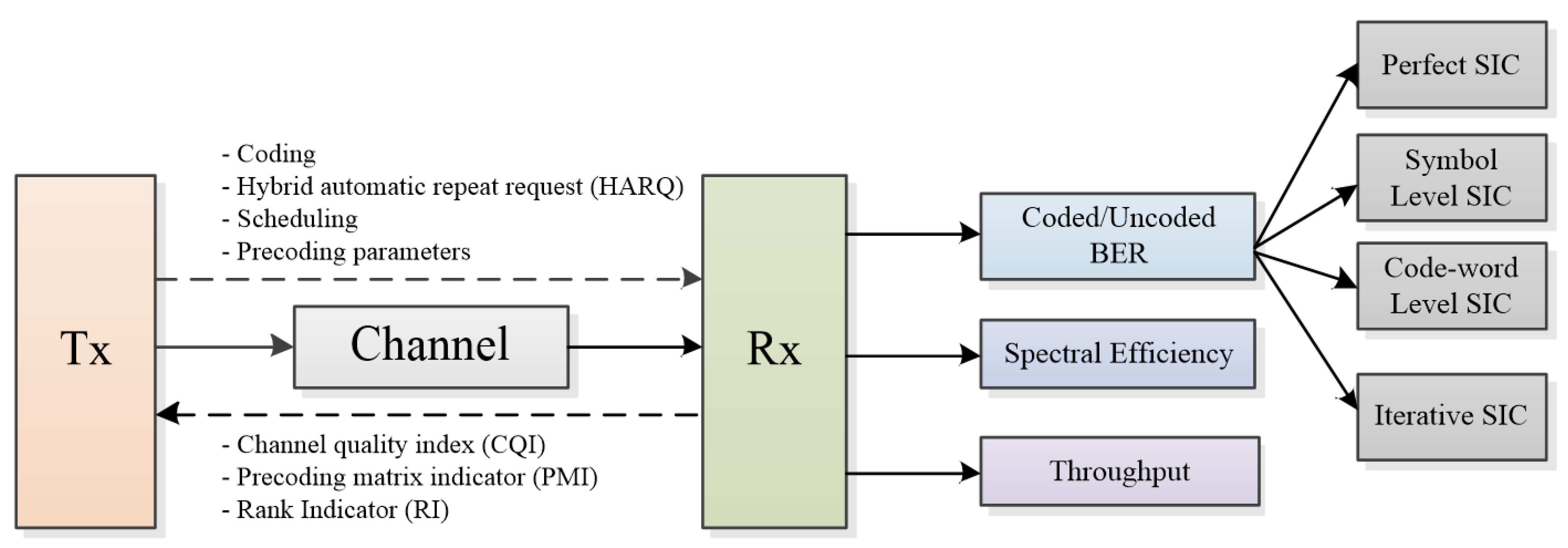
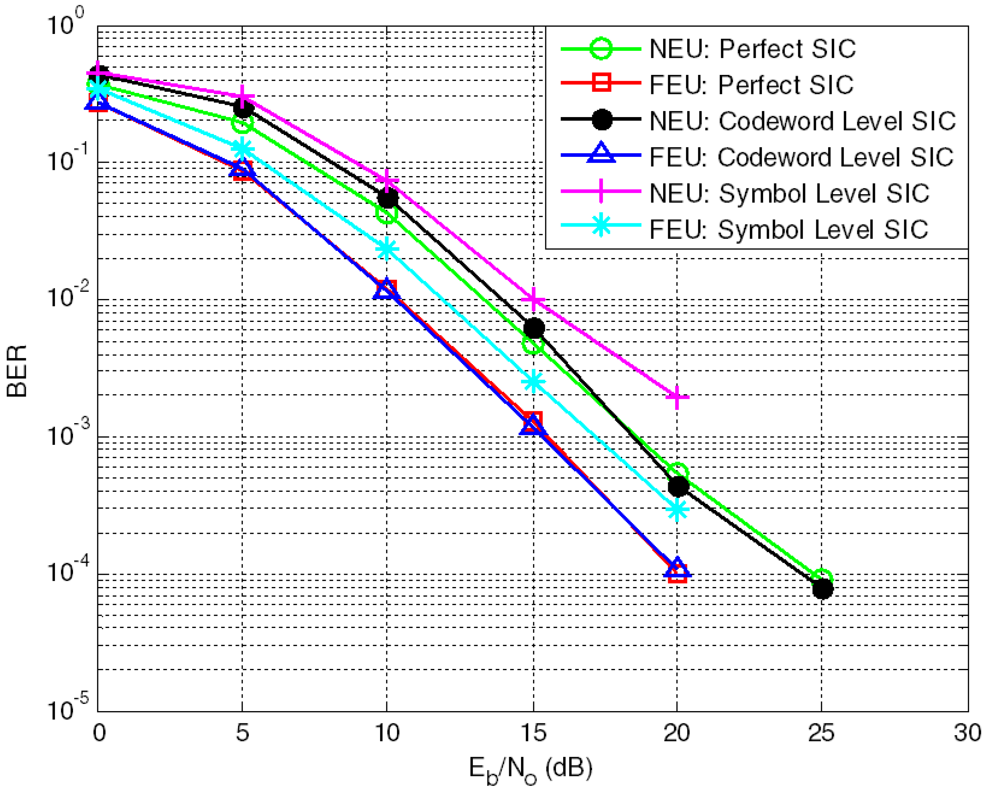
  • Different forms of SIC are considered for downlink scenarios such as perfect SIC, symbol level SIC, code-word level SIC and iterative SIC.
  • Generally, the trend followed by the research community is to focus on spectral efficiency as a performance metric to analyze the performance of any proposed techniques for SC and MC-NOMA based systems. However, the presented simulator provides an environment to evaluate the performance using different metrics in addition to the spectral efficiency, e.g., uncoded bit error rate (BER), coded BER and throughput.
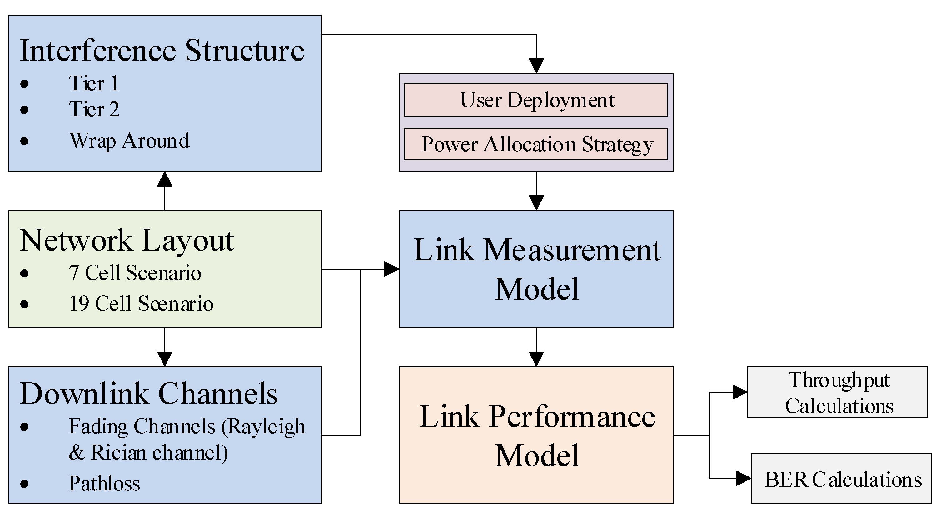
  • For system-level analysis, 7-cell and 19-cell scenarios are considered together with the wrap-around concept. Normally, NOMA-related publications only analyze two users; however, we also examine the effects of more than two users in a cell.
  • Intercell interference is also considered for multicell scenarios.
The novelty of this research work is assured by the fact that the NOMA simulator is the first of its type to connect different features of SC and MC-NOMA under one platform, where some of these contributions have already been presented in the very recent literature or have not been considered previously. The NOMA simulator is still not an open source because much work is in progress to upgrade, where the following versions comprise various factors such as mobility and massive MIMO setups. Furthermore, this upgradation focuses on different power allocation schemes, channel models, interference cancellation techniques, and channel coding methods other than convolutional coding. To the best of the authors’ knowledge, our simulator is the first work to be presented in the context of NOMA link-level and system-level analyses. This work also reinforces the efficient performance of MC-NOMA for both Gaussian and non-Gaussian channels together with intercell interference. The efficacy of the multi-user detection (MUD) approach for SIC to separate multiplexed user information is critical for NOMA-based systems. A small detection error might result in erroneous detection of all users’ data, irrespective of the high channel gain. Therefore, the additive white Gaussian noise (AWGN) base ambient noise and impulse noise can lead to deteriorated data recovery. Hence, channel coding is applied in the form of convolutional coding on MC-NOMA to avoid impulse noise, which is a key feature of non-Gaussian channels; thus, it provides a more realistic scenario in this regard. In addition, linear precoding (LP) is suggested to improve the performance of uncoded and coded MC-NOMA by introducing diversity in the system along with a reduction in the peak-to-average power ratio. It is believed that this is the first work wherein the superiority of coded MC-NOMA over uncoded MC-NOMA with LP is highlighted in the presence of AWGN, impulse noise, and intercell interference.
The remainder of this article is organized as follows: Section 2 describes the detailed structure of the NOMA link-level simulator, and Section 3 presents the system-level simulator. The Structure of MC-NOMA is given in Section 4, followed by the validation of the presented simulator in Section 5. Coded MC-NOMA in the presence of non-Gaussian channels along with the description of the system model and BER analysis of uncoded and coded MC-NOMA with LP is also presented in Section 6. Finally, the concluding statements are presented in Section 7.

2. The NOMA Link-Level Simulator

2.1. Structure of the NOMA Link-Level Simulator

The main structure of the MC-NOMA link-level simulator is explained in this section; however, for comparison purposes, a broad description of SC-NOMA has been briefly addressed alongside MC-NOMA. MC-NOMA uses orthogonal frequency-division multiplexing (OFDM) as a multi-carrier modulation technology that permits the simultaneous distribution of a single subcarrier to many users; however, SC-NOMA does not use OFDM processing. The structure of the downlink MC-NOMA simulator comprises three parts, i.e., transmitter, channel and receiver as shown in Figure 1, and its details have been provided in the following subsections. Error-free propagation for signaling is assumed for simplicity. The reason for this assumption is supported by the fact that signaling channels only face errors if the data channels are already facing severe conditions as mentioned in [10]. Signaling information usually comprises a precoding matrix indicator (PMI), channel quality indicator (CQI), coding, and rank indicator. The uplink transmission, which works mainly on the CQI, is not considered in the initial stage of the simulator. However, it will be added to the next version of the simulator.

2.2. Transmitter

A detailed description of the transmitter for the downlink link-level NOMA simulator is presented in Figure 2a. Unlike time-division multiple access and frequency-division multiple access, the power-domain NOMA multiplexes multiple users in the power domain. Conventional multiple access systems, as standardized for 4G systems, are based on OFDMA, where resources are exclusively allocated to users [22]. No two users can share the same resources simultaneously, which reduces the overall capacity of the system for high data rate communication. Therefore, multiplexing users in a non-orthogonal fashion in the form of NOMA is one of the many potential solutions to increase the system capacity for FRA. In NOMA, users are free to utilize the entire bandwidth based on the difference in their power levels. The flexibility of subcarrier reuse within the same cell, as well as its combination with other technologies, has attracted the interest of the research community with regard to NOMA standardization.
Three important processes performed at the transmitter side that make NOMA different from OMA-based systems are as follows,
  • User pairing;
  • Power allocation;
  • Superposition coding.
NOMA-based systems exploit the difference in channel conditions to pair users. Users close to the base station, i.e., near-end users (NEUs), are assumed to have better channel conditions; thus, low power is assigned for successful communication. On the contrary, users at a distance far away from the base station, i.e., the far-end users (FEUs), experience bad channel conditions, and consequently, high power is assigned to them. The greater the channel gain difference between users, the higher the sum-rate capacity to be achieved. Power allocation to different users based on their channel conditions is one of the many critical factors in NOMA-based systems. Although different power allocation techniques have been proposed in the literature; fractional transmit power allocation (FTPA) is considered in most research articles owing to its simplicity [23,24,25]. Another important process to be performed at the transmitter is SC. It is used to multiplex users at different power levels. Thus, a combination of NEU and FEU signal x ( t ) after SC and power allocation is given as [19];
x ( t ) = P 1 x 1 ( t ) + P 2 x 2 ( t )
where x 1 and x 2 represent the data, and P 1 and P 2 denote the power allocated to NEUs and FEUs, respectively. For the MC-NOMA-based system, the superimposed signal must pass through further processing blocks before its final transmission through the channel. One of these significant processes is the mapping of a super-coded signal on the sub-carriers present in the system. This mapping is performed using the inverse fast Fourier transform (IFFT). Subsequently, a cyclic prefix (CP) was inserted to reduce the effect of inter-symbol interference. CP is redundant information and comprises the last samples of the symbol, appended at the start of the symbol. The signal is now ready to transmit and propagate through the multipath channel.

2.3. Channel Models

The proposed NOMA link-level simulator supports the block-fading channel. In the block-fading channel, the channel response is constant for a specific duration of time. This duration is usually equal to the transmission duration for one sub-frame. Therefore, for one sub-frame, the channel conditions are assumed to remain constant. Such channels are relatively easy to handle compared to fast fading channels, where the channel changes its response even for each symbol in one sub-frame. At this stage, the different channel models considered for the simulator are listed below:
  • Additive white Gaussian channel (AWGN);
  • Flat Rayleigh fading;
  • Flat Rician fading.
AWGN is the simplest channel model that does not consider any type of fading and only deals with the linear addition of background white noise. The amplitude of AWGN follows a Gaussian distribution. To study the fading effects on the NOMA signal, Rayleigh, and Rician fading models were considered. The Rayleigh model is reasonable for scattered or reflected paths. However, it does not consider the line of sight (LOS), which is not the case with the Rician fading model where LOS is also taken along with non-LOS. As the presented simulator is the first version of the NOMA simulator, the channel models are limited to these models only. However, for the next upgraded version, ITU Pedestrian B, ITU Vehicular A and Winner models were incorporated.

2.4. Receiver Design

Figure 2b shows the receiver implementation of the MC-NOMA-based system with SIC. The first step to be performed at the receiver for OFDM-NOMA is CP removal. After this equalization is executed to undo the channel effects. The next step to be carried out on the equalized data is a fast Fourier transform (FFT), which converts the time-domain signal into a frequency-domain one. As NOMA is based on multiplexing of users’ data in the power domain at the transmitter side via SC, multiuser detection (MUD) is required at the receiver side to de-multiplex the data of multiple users. SIC has been widely adopted as an MUD technique for NOMA-based systems in the literature [26,27,28,29]. FEU with large power treats the NEU as noise and detects its signal with a high probability of success. On the contrary, NEU considers FEU as interference and thus, performs MUD in the form of SIC. The receiver design of the proposed NOMA simulator is also based on SIC. Different variants of SIC are considered in the proposed downlink NOMA simulator, which is discussed below.

2.4.1. Perfect SIC

Perfect or ideal SIC works on the assumption that the NEU has perfect knowledge of the FEU data, and the interference is perfectly canceled at the NEU. Perfect SIC gives the maximum upper bound of the performance. The detection of NEU in terms of perfect SIC can be expressed as [30],
x 1 ^ = y 1 P 2 x 2 P 1
where y 1 and x 1 ^ denote the received and estimated decoded signals at the NEU, respectively. P 1 and P 2 are powers allocated to the NEU and FEU, respectively. x 2 is a perfectly decoded signal of the FEU whose knowledge is available at the NEU. Signal detection involves compulsory demodulation and an optional channel decoding process, provided that channel coding is applied at the transmitter side.

2.4.2. Symbol-Level SIC

Symbol-level SIC does not involve any type of channel coding. First, the FEU was detected without channel decoding. FEU can be detected as [31];
x 2 ^ = y 2 P 2
where . shows the demodulation process in absence of channel decoding. NEU is assumed to have complete knowledge of the FEU, so the SIC process is performed as follows;
y ˜ 1 = y 1 P 2 x 2 ^
where, y ˜ 1 is the estimated received signal of the NEU after the SIC process. This signal is further demodulated to retrieve the data transmitted for the NEU, given as
x 1 ^ = β 1 P 1

2.4.3. Code-Word-Level SIC

The only difference between symbol-level SIC and code-word-level SIC is channel encoding and decoding at the transmitter and receiver sides, respectively. Code-word-level SIC involves channel coding after the modulation process before SC, whereas at the receiver side, channel decoding is performed before the demodulation process. Therefore, channel encoding/decoding results in a drastic reduction in the probability of error at the expense of an increase in system complexity. The perfect SIC provides the upper bound limit as a reference to compare the other extracted results from each new idea presented by the researchers. Therefore, the complexity of the perfect SIC is always greater than both the code-word-level and symbol-level SIC because the receiver knows the channel statistics to fully subtract from the received signal.

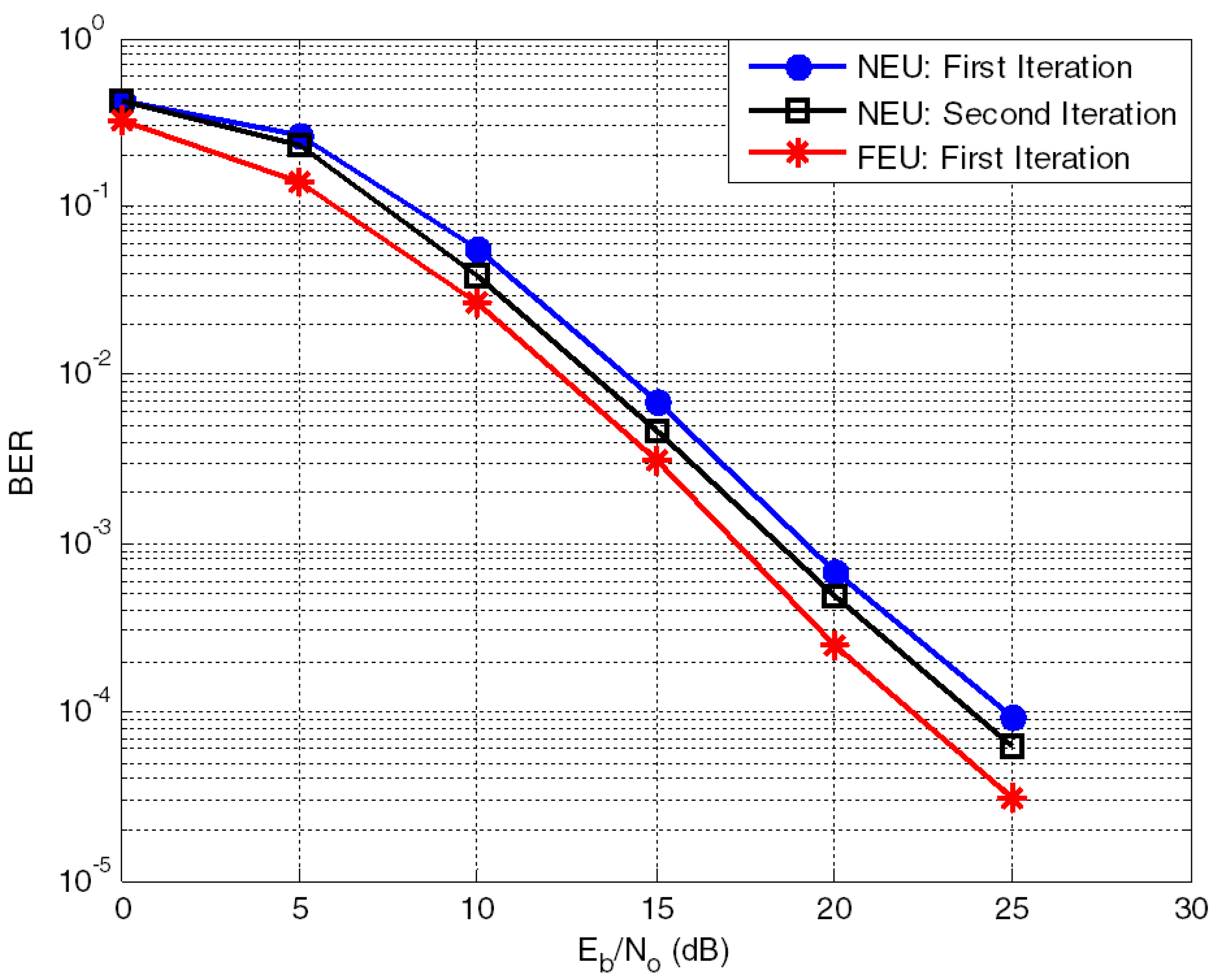
2.4.4. Iterative SIC

As the name suggests, iterative SIC is based on multiple iterations of symbol detection to reduce interference among users. By exploiting the prior information about interference for estimation, the next iteration improves the performance of the receiver at the cost of processing delay. Thus, the complexity of the iterative SIC is directly proportional to the number of iterations. However, the drawback of iterative SIC is that the performance of the current iteration is dependent on the information coming from the previous iteration; therefore, any inaccuracy may result in the form of an error and can propagate throughout the detection process.

2.4.5. Features and Considered Scenarios

The NOMA link-level simulator was based on MATLAB simulations. The NOMA system works on the principle of user pairing with different channel gains; therefore, a minimum of two users are required in any simulation scenario. Owing to the restriction of a minimum of two users, a single-input–single-output system is not possible in NOMA systems. Thus, multiple users in a single cell are required in all the simulated scenarios. Although most research related to NOMA is limited to two-user pairing [32,33], more than two users in NOMA systems and their power allocation is still under investigation by various research groups [1,34]. The proposed NOMA link-level simulator also works on the pairing of two users only until now, but it can be extended to multiple users in the next release of this simulator.

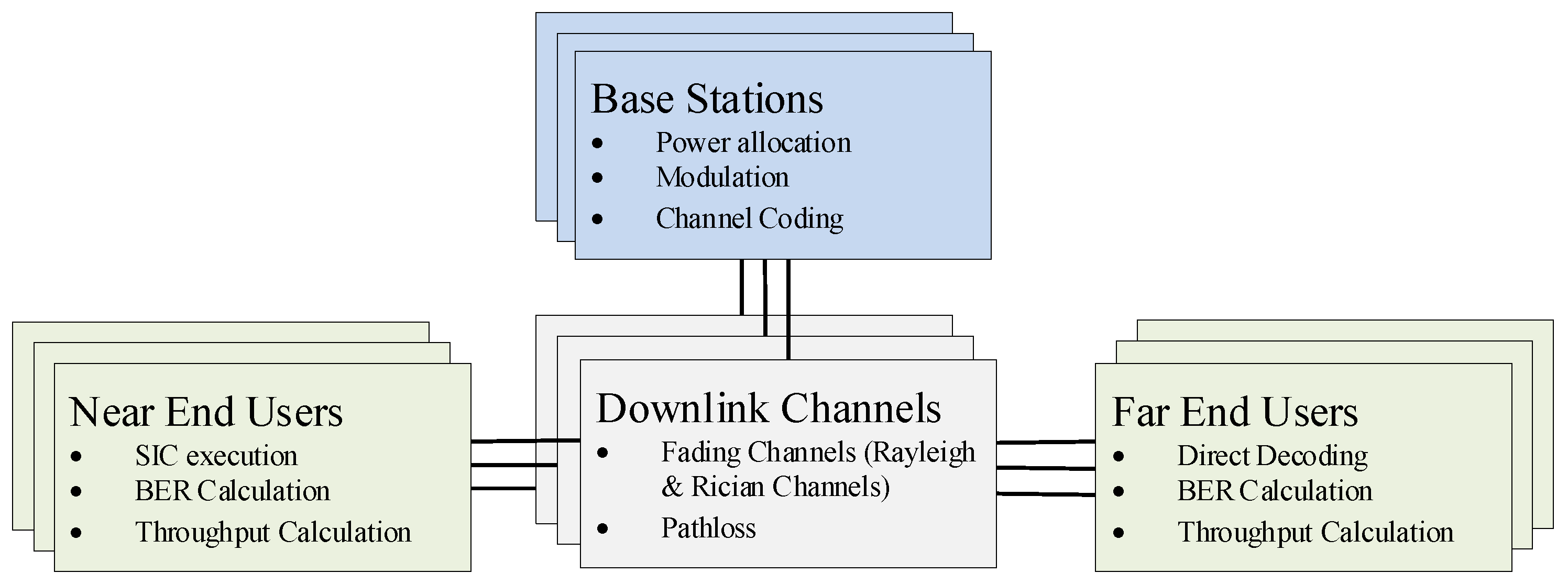
3. The NOMA System-Level Simulator

This section provides a detailed account of the MC-NOMA system-level simulator. The overall structure of the system-level simulator is discussed and its complexity is analyzed in this section.

3.1. Introduction to the NOMA System-Level Simulator

The performance of an entire network was analyzed in system-level simulations. In conventional cellular networks, such a scenario comprises multiple cells with their respective base stations (BSs) that cover a defined area wherein many users are located. Simulations at the physical layer level enable the investigation of adaptive modulation coding (AMC) for NOMA and modeling of channel coding; however, estimating or measuring the impact of cellular planning, scheduling, or interference on a large scale with a larger number of BSs with mass connectivity is difficult. A practical way of performing system-level simulations is to abstract the physical layer using simplified models while maintaining high accuracy at low complexity. This is due to the vast amount of computational power required for performing system-level simulations of radio links between the BSs and their connected users.

3.2. Structure of the NOMA System-Level Simulator

The researchers in [10], presented the structure of their simulator in three major blocks; The transmitter, channel model, and the receiver. The channel model connects the transmitter and receiver blocks and is used to transmit downlink data, while signaling and uplink feedback are considered to be error-free. Similarly, our system-level structure of NOMA simulator consists of three major building blocks; interference structure, downlink channels and measurement models. The link measurement model measures the link quality and performs link adaptation and resource allocation for each user in a group, where resource allocation is accomplished by considering the difference in channel gains between the users paired together. Based on the measurements from the link measurement model, the link performance model predicts the BER of the link, based on the received signal-to-interference noise ratio (SINR) and the selected modulation and coding at the transmitter, as presented in [20]. Figure 3 illustrates the interaction between the link measurement model and link performance model in the form of a block diagram.
The implementation of the presented simulator follows the structure shown in Figure 4. Transmission sites were created to generate the network topology. Each transmission site comprises of one BS, which is responsible for assigning resources, precoding matrices, power allocation, and a suitable modulation and coding scheme to each user connected to the BS. The resources, modulation and coding schemes are assigned to each user based on the channel gain of each user in a group. For simplicity, we considered two users in each group, that is a pair of users with one user having a high channel gain and the other user having a low channel gain. For performing SIC, the users with a stronger channel gain follow the same interference cancellation techniques as explained in the earlier sections. The scenarios considered in our system-level simulator are explained in the following section.

3.3. Features of the System-Level Simulator

We considered three scenarios to assess the features and potential of the proposed system-level NOMA simulator that includes the 7-cell scenario, 19-cell scenario, and 19-cell scenario with wrap around. These three scenarios are explained briefly, where users are randomly positioned in each cell for every system-level simulation. In our proposed NOMA system-level simulator, we consider a two-tier interference model, that is a user experiences interference from the 1st tier and the 2nd tier of cells.

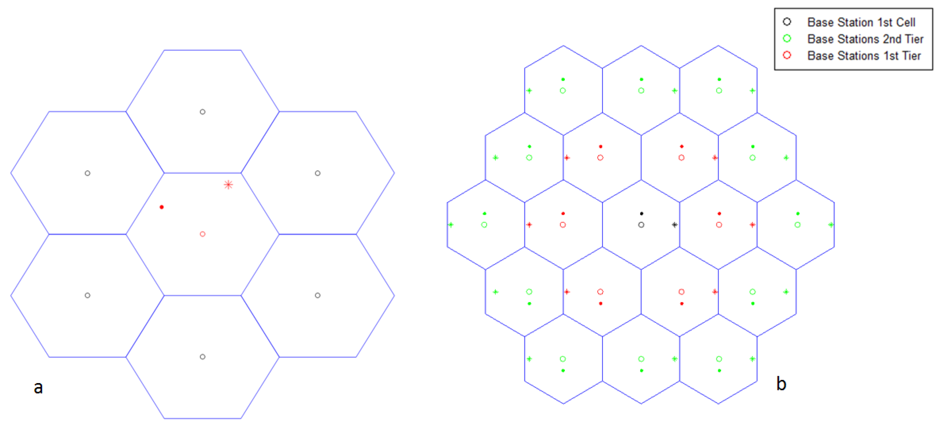
3.3.1. Seven-Cell Scenario

This scenario is illustrated in Figure 5a where seven cells share the boundary(s). Six cells surround the center cell, each of which follows a hexagonal cell structure. Each cell comprised of one BS and two users paired together. These two users are paired together based on the channel gain difference and their corresponding resources are assigned to them accordingly. Each user in a cell experiences interference from its neighboring cell’s BSs, and this interference model is considered for each cell. The link performance model in this scenario considers the interference experienced by a user from its six neighboring cells and the consequent BER is calculated.

3.3.2. Nineteen-Cell Scenario

This scenario is illustrated in Figure 5b, wherein there are 19 cells in total that share a boundary(s). Each cell comprised two paired users connected to a single BS. Each user in a particular cell experiences interference from all of its 18 neighboring cells, and the link measurement model calculates the BER accordingly.

3.3.3. Nineteen-Cell Scenario with Wrap around Effect

The wrap-around effect was used to construct a 19-cell scenario. In a 19-cell situation, border cells do not share all of their hexagonal boundaries with their neighbors. This indicates that border cells are not subjected to the same amount of interference as the inner cells. As a result, to simulate the identical interference condition as the users in the central cell, two layers of cells are considered around the boundary cells. As a result, when the link performance model calculates the BER for users in the boundary cells, the results are equivalent to those for users in the center cell. Ref. [30] explains the 19-cell situation with the wrap-around effect in detail.

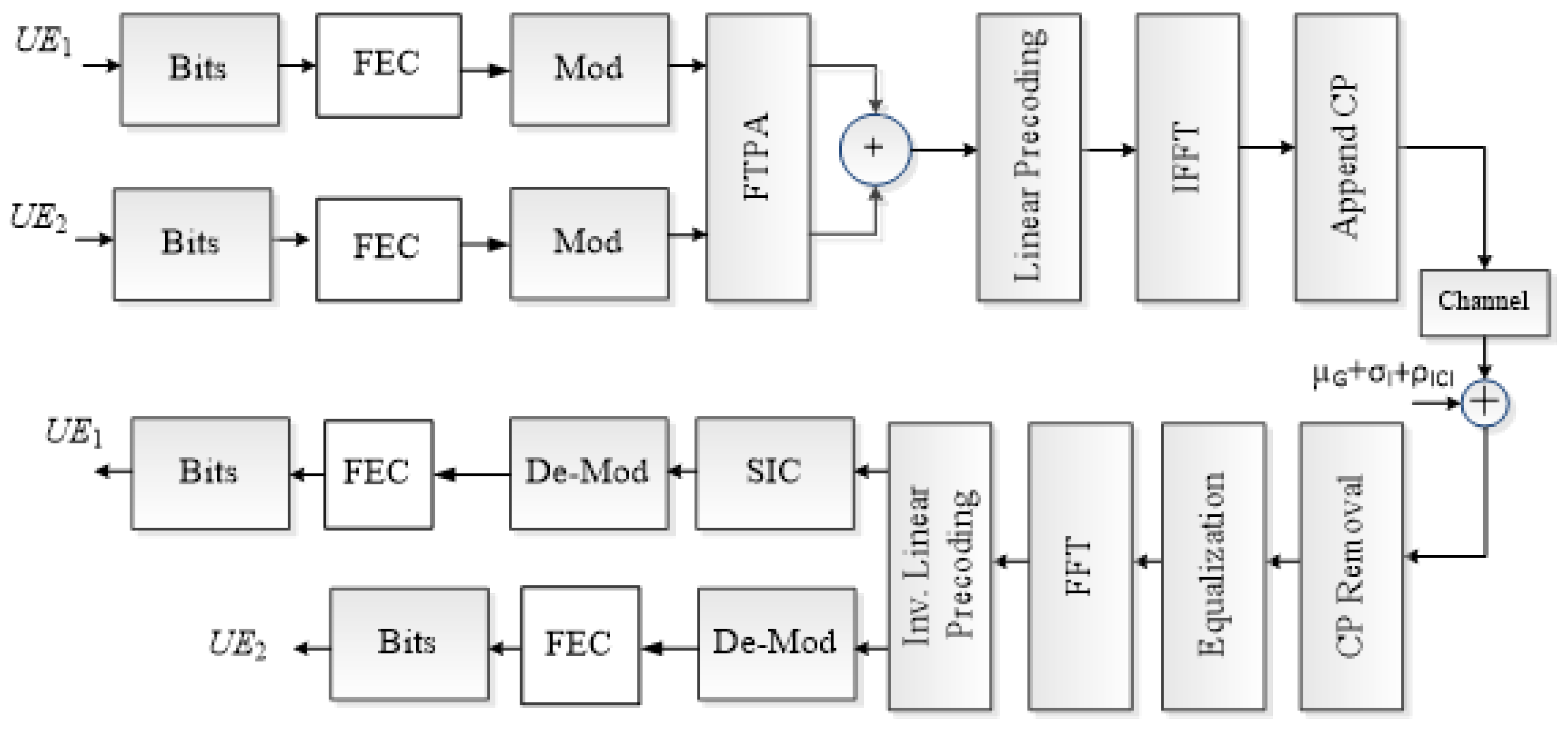
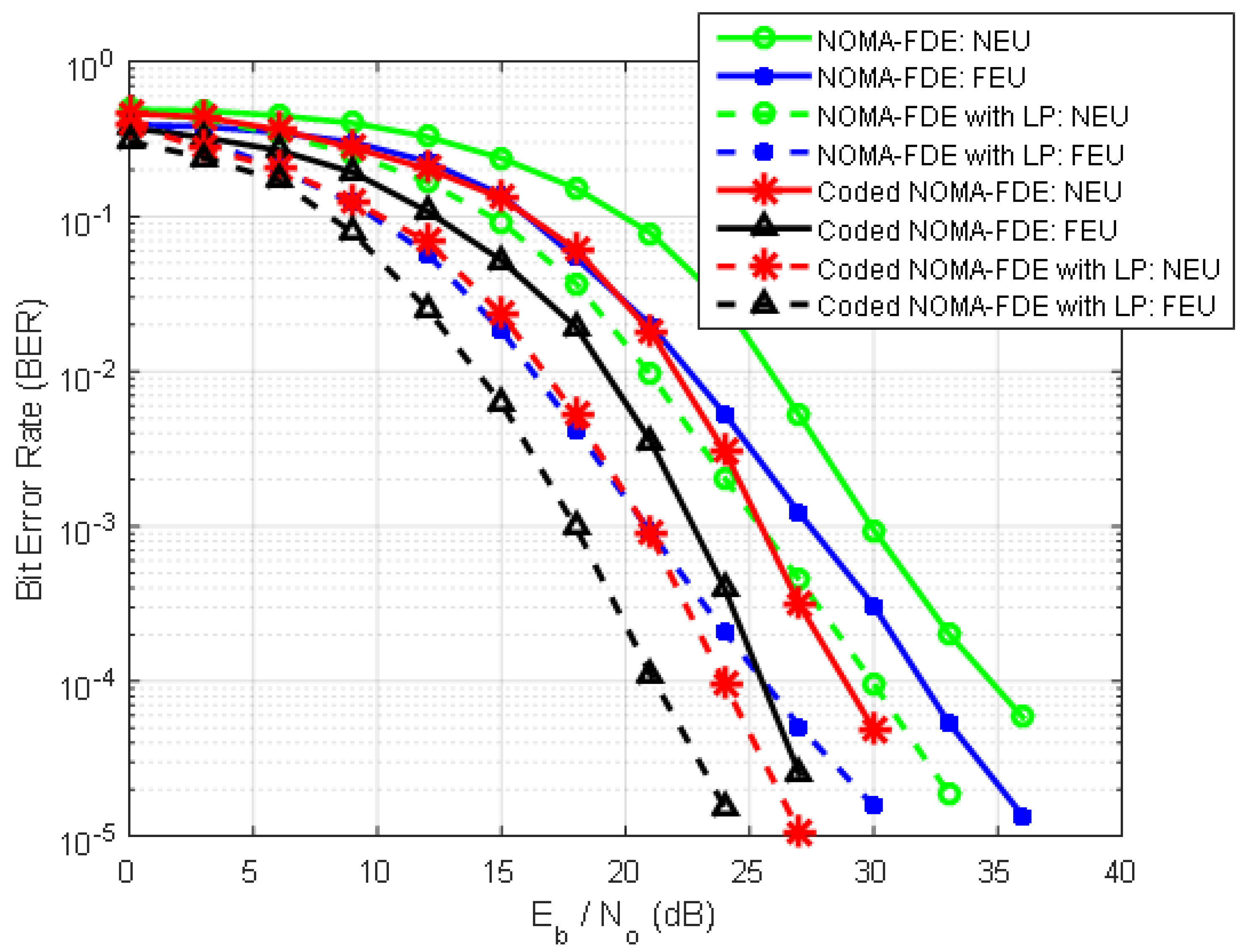
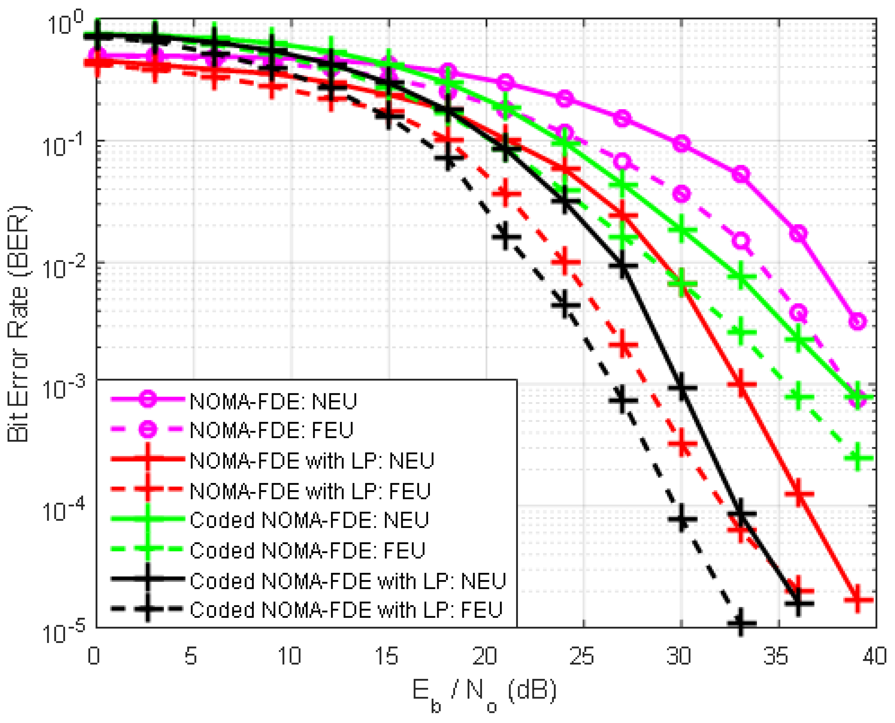
4. Coded MC-NOMA in the Presence of Non-Gaussian Channels

Structure of MC-NOMA

In this section, the proposed MC-NOMA model is based on channel coding and LP, as shown in Figure 6, is discussed. Information bits from both the NEU and FEU are passed through the channel coding block to introduce redundancy for error correction. Convolution coding as forward error correction (FEC) is considered in the proposed system owing to its easy implementation and better performance in noisy channels [35,36]. The encoder output is modulated and then power allocation is applied depending on the channel gains. The multiplexed signal x(t) from both NEU and FEU after SC is directed to a linear precoding block, which is implemented through the Walsh Hadamard Transform (WHT) owing to its simplicity [36]. WHT spreads information either in the entire system or half of the system and thus improves the BER performance in the frequency-selective channel. The superimposed signal is multiplied with the WHT kernel W H to obtain the precoded signal X p such that X p = X W H where X is the matrix representation of x ( t ) and W H = 1 H + W H 1 + W H 1 + W H 1 W H 1 . LP breaks the autocorrelation among symbols, thus resulting in a significant improvement in the selectivity of the channels. The IFFT is applied to the incoming precoded stream to convert the frequency-domain symbols into the time-domain one. CP is also appended after an inverse transformation to circumvent inter-symbol interference. The transmitted signal is then passed through the Rayleigh fading channel, which is corrupted by both AWGN and impulse noise to provide a more realistic simulation scenario. Impulse noise can be modeled through Middleton noise model A, the explanation of which can be obtained in [37,38,39]. Moreover, inter-cell interference is considered a limiting factor in obtaining lower BER. Thus, the received signal r ( t ) at each U E l ( l = 1 , 2 , 3 , , k ) can be expressed as,
n l = h l x + μ G + σ I + ρ I C I
where h l represents the channel coefficients, and μ G denotes AWGN with zero mean and variance ϕ G 2 . σ I denotes impulse noise, whereas intercell interference is represented by ρ I C I . At the receiver, all processing steps were performed in the reverse order. The CP is removed, and FDE is applied to undo the channel effects. In the following step, FFT is applied to convert the signal from the time domain to the frequency domain and then provided to the inverse WHT to obtain the signal. SIC is applied at this stage to separate multiplexed signals. Demodulation and channel decoding processes are performed to extract the transmitted bits for both users.
As our study comprises NOMA as multiple access for two users to present the potential it holds for 5G wireless networks and more than two users, the research is at the infancy stage; thus extending the proposed work for multiple numbers of users is not possible. User pairing based on channel gains and power distribution among different users is a key issue, and several studies are underway to solve this restriction.

5. Verification of the NOMA Simulator

This section deals with the abilities of the NOMA simulator by illustrating some of the simulated results produced as part of our recent research. The performance metrics presented in this section are the BER, throughput, and spectral efficiency. Simulations were carried out according to the parameters listed in Table 1. All simulated results are produced considering 16 quadrature amplitude modulation (QAM) and quadrature phase-shift keying (QPSK) for NEU and FEU, respectively, in the presence of AWGN with a Rayleigh fading channel. The given simulated results are mostly related to link-level analysis; however, the system-level simulator results will be discussed in the upgraded version of this simulator.

5.1. Exemplary Simulated Results

5.1.1. Channel Coding

Channel coding was used to detect and correct errors in the transmitted data. Redundancy is added to the transmitted signal and then at the receiver side, which are used by the receiver to recover distorted information. The proposed NOMA link-level simulator employs convolutional code for channel coding. These codes have been standardized in LTE; therefore, for our simulator, we also considered them with different coding rates. The performance of uncoded and coded NOMA-based systems was evaluated in terms of BER. Figure 7 shows the performance comparison of uncoded NOMA and coded NOMA in the presence of perfect SIC with different code rates, k for both NEUs and FEUs. For a BER of 10 3 , E b / N o required for uncoded NOMA and coded NOMA with k = 1 2 for NEU is 25 dB and 22.5 dB, respectively. This is because the near user experiences interference at the SIC level, and the absence of redundancy increases the interference by the high-power user. The far user simply subtracts the near user signal as noise from the combined received signal because the power level of the near user signal is at the noise level at the far user’s distance. Similarly, for the FEU, E b / N o required for the uncoded and coded system with k = 1 2 is 20 dB and 17 dB, respectively, for a BER of 10 3 . It shows a 3-dB gain in the case of the FEU as compared to the NEU, where the achieved gain is 2.5 dB. As k is changed from 1 2 to 1 4 , the coded system performs better when E b / N o is equal to 21.5 dB and 16.5 dB for NEU and FEU, respectively, at a BER of 10 3 . The performance of coded NOMA is better than that of uncoded NOMA in terms of the BER. This supports the fact that increased redundancy in coded NOMA enhances the performance, but at the cost of increased computational complexity compared to uncoded NOMA.

5.1.2. Bit Error Rate

To evaluate the receiver performance, the BER was investigated with different SIC variants as interference cancellation techniques. The BER performance of perfect, symbol-level and code-word-level SIC for NEU and FEU with different allocated powers is presented. Adaptive modulation is applied by considering 16-QAM for the NEU and QPSK for the FEU. FTPA is used for power allocation with two different sets, that is, P 1 , P 2 = 0.1 , 0.9 and P 1 , P 2 = 0.2 , 0.8 . The BER performance of different receivers with P 1 , P 2 = 0.1 , 0.9 is shown in Figure 8. For a BER of 10 3 , E b / N o required for NEUs with perfect SIC, the code-word-level SIC and symbol-level SIC are 13.5 dB, 14 dB and 15 dB, respectively. The code-word-level SIC achieves almost the same performance as perfect SIC with a gain of 1 dB as compared to symbol-level SIC. The same goes for FEU, where code-word level SIC achieves a performance gain of 2.5 dB. However, this performance gain comes at the cost of computational complexity in the form of channel coding and decoding.
Figure 9 also shows the performance of SIC receivers with different power allocations of P 1 , P 2 = 0.2 , 0.8 . For NEU, perfect and code-word-level SIC achieves the same level of performance with a requirement of E b / N o equal to 16 dB and 16.5 dB for a BER of 10 2 , respectively. However, the performance of symbol-level SIC degrades, which shows its incapability to handle errors as compared to other receivers. Furthermore, Figure 8 and Figure 9 show that the difference in user power allocation coefficient effects the BER performance. If the power of the NEU is increased, the BER improves of the NEU; however, in comparison with the combined BER, the FEU takes the effect of less power and shows a slightly higher BER. Another simulated result related to SIC receiver designs for a NOMA system is associated with iterative SIC. An increase in the number of iterations promises better BER performance with increased complexity.
Figure 10 shows that the SIC is performed at the user with the best channel gain; hence, the iterative process improves the NEU performance. For a BER of 10 3 , E b / N o required for NEU with iterative SIC for the first and second iterations is 18.5 dB and 19.5 dB, respectively. Therefore, a performance gain of 1 dB was achieved in the second iteration. Thus, it validates the early assertion that as the number of iterations is increasing, the BER of the receiver improves; however, the price for this improvement is paid in the form of increased computational complexity.

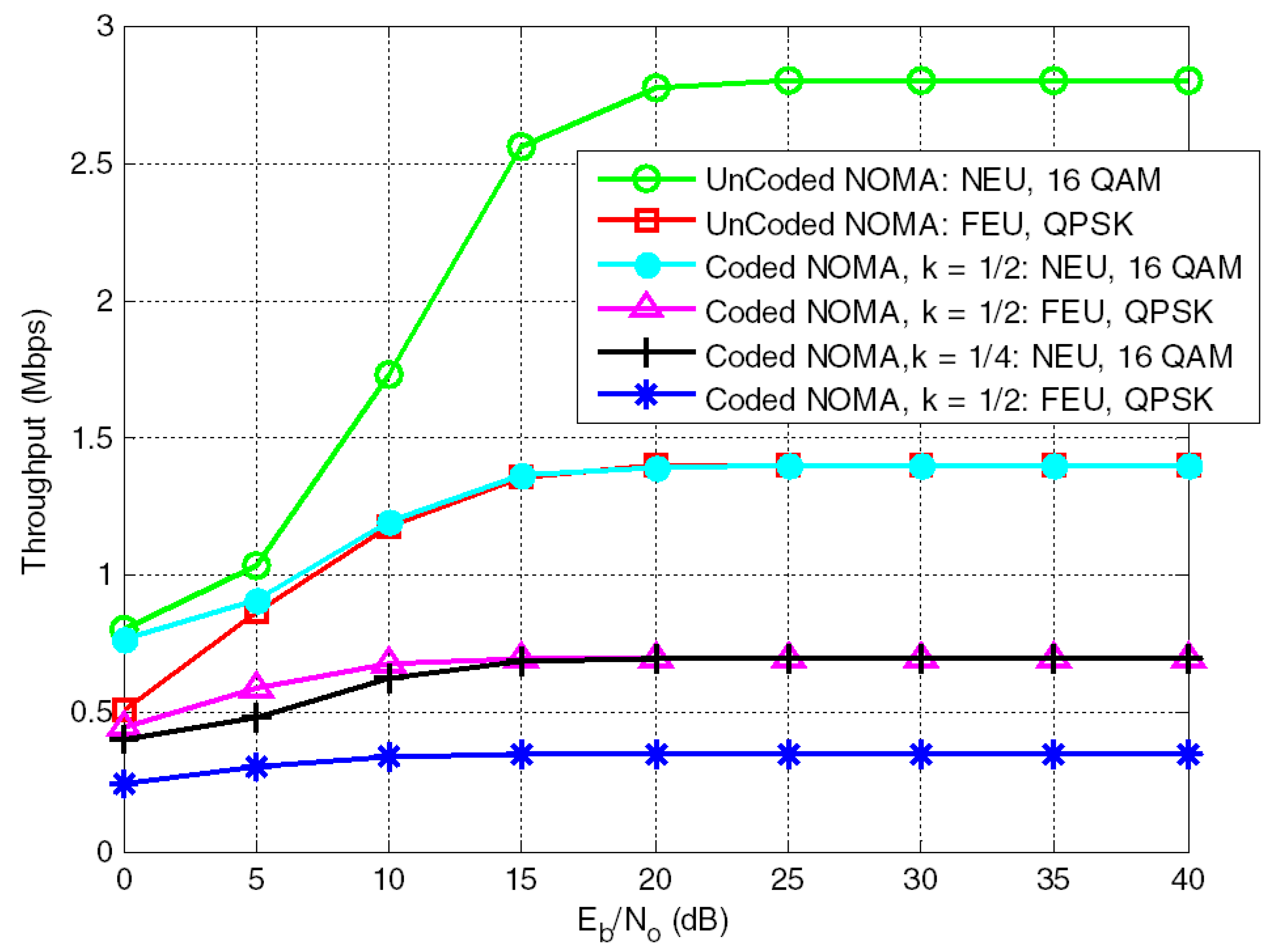
5.1.3. Throughput Analysis

The throughput of a system is a measure that determines the successful transmission over a communication channel with channel impairments. NOMA is believed to improve throughput compared to OFDMA [40,41,42]. However, the throughput of NOMA depends on the pairing of users and the power allocation for each UE along with the modulation and coding scheme. For link-level analysis, the throughput ϵ of the system can be expressed as [38]
ϵ = ( 1 P E R ) × n b / p k T p k ( s )
where PER denotes the packet error rate, n b p k is the number of bits per packet, and T p k is the duration of a single packet. Figure 11 demonstrates the throughput performance of NEU and FEU with perfect SIC in the Rayleigh fading channel in the presence of AWGN. Convolutional coding was also applied at different coding rates. Although with channel coding, the system can detect and correct more errors, which improves the BER performance, but at the same time, redundant bits lower the throughput of the individual user.

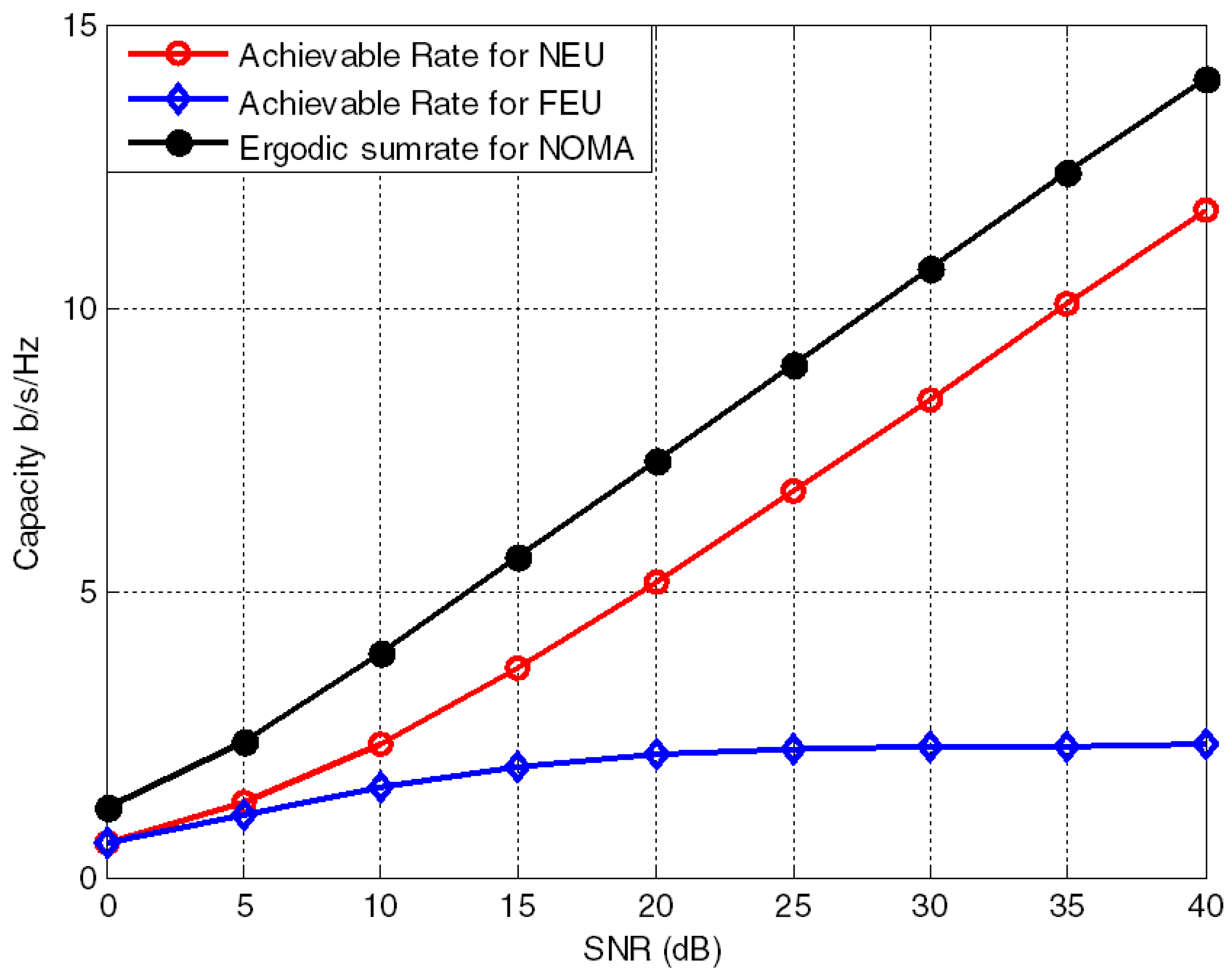
5.1.4. Ergodic Sum Rate

NOMA is believed to improve the spectral efficiency of FRA by up to three folds [30]. Typically, the research related to NOMA is considers two users in a pair, but this article provides additional analysis for more than two users. However, if we consider more than two users in a pair, say three, the intermediate user will perform SIC for the high-power (far) user’s signal while simply subtracting the near user signal as noise. Hence, the achievable data rate for the three users is given as [34,39]
R N E U = B log 2 1 + P N E U h N E U 2 η 1
R I E U = B log 2 1 + P I E U h I E U 2 P N E U h I E U 2 + η 2
R F E U = B log 2 1 + P F E U h F E U 2 P N E U h F E U 2 + P I E U h F E U 2 + η 3
where R N E U , R I E U and R F E U are the data rates of the NEU, IEU, and FEU, respectively. B is the total system bandwidth of the channel whereas η 1 , η 2 , and η 3 represent the AWGN noise. The power coefficient in the denominator show the interference from users with a higher channel gain. As B is the same for all users because the entire bandwidth is available, B can be ignored in the equations. Therefore, the sum rate of the NOMA system with two users is given as
R s u m 2 = log 2 1 + P N E U h N E U 2 η 1 + log 2 1 + P F E U h F E U 2 P N E U h F E U 2 + η 2
where, the sum rate of the NOMA system for the three users is given as
R s u m 3 = log 2 1 + P N E U h N E U 2 η 1 + log 2 1 + P I E U h I E U 2 P N E U h I E U 2 + η 2 + log 2 1 + P F E U h F E U 2 P N E U h F E U 2 + P I E U h F E U 2 + η 2
The ergodic sum-rate capacity of the NOMA system is shown in Figure 12 and Figure 13.

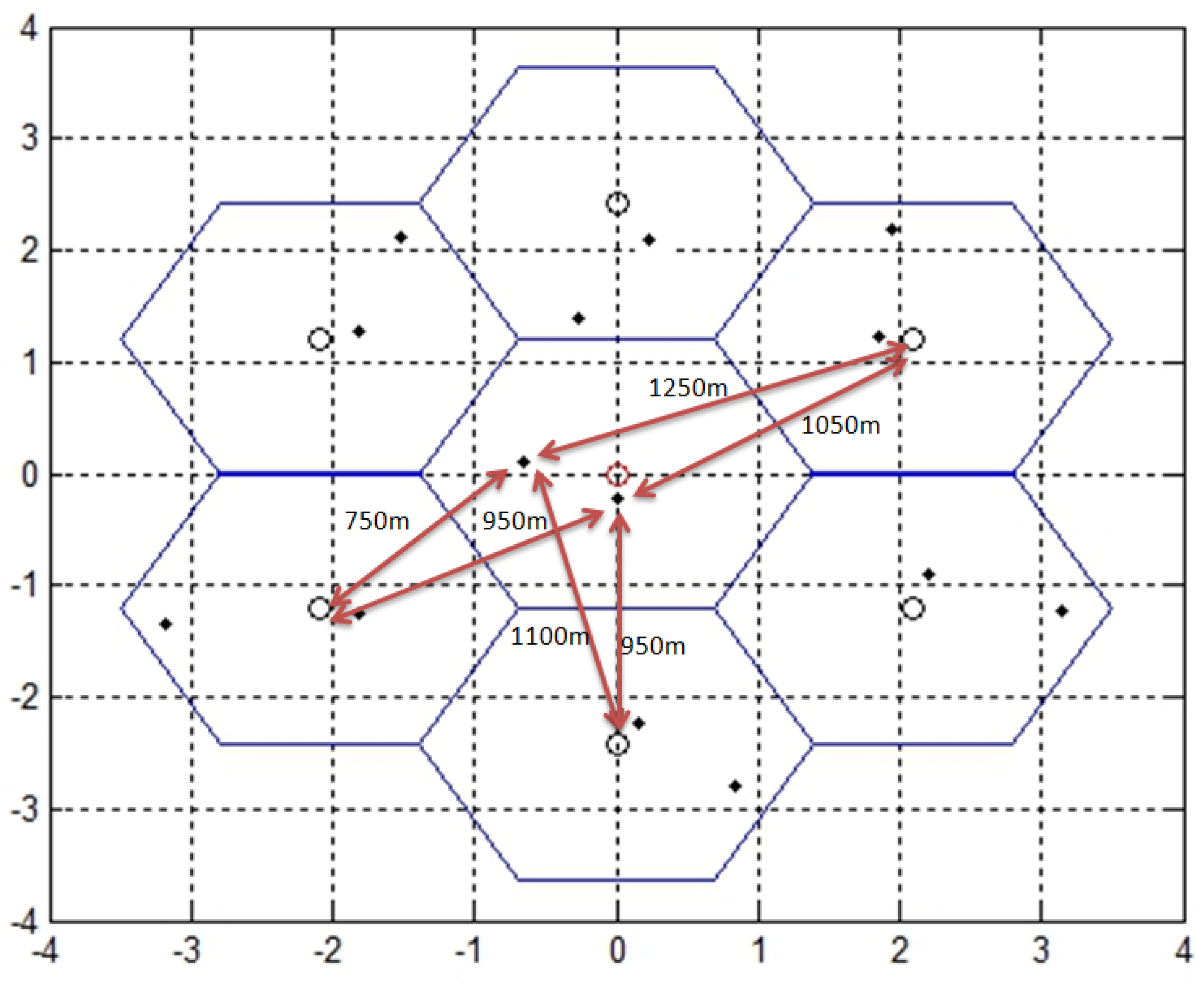
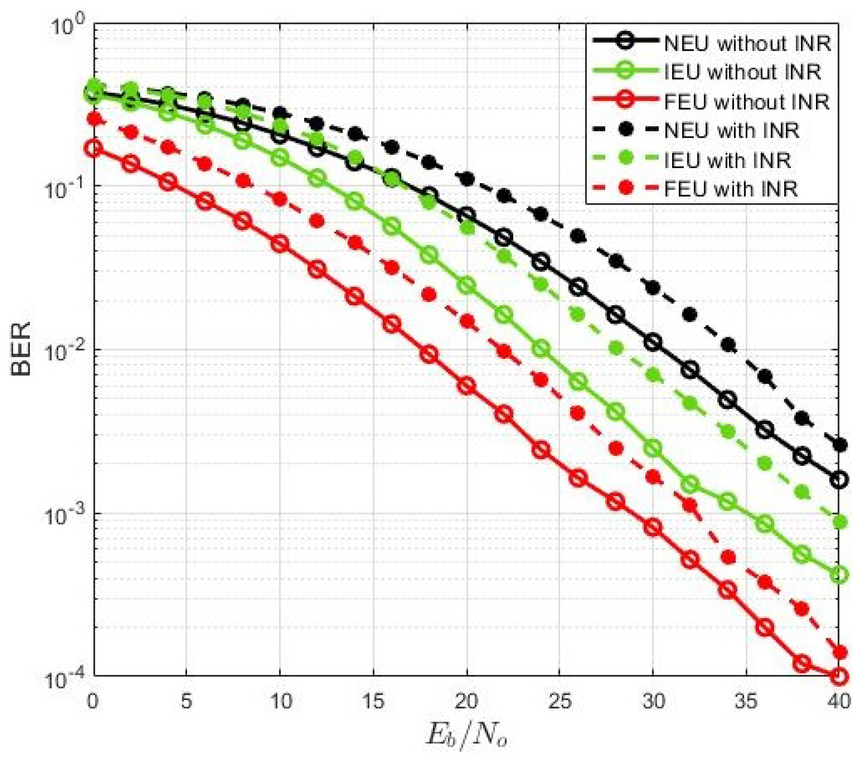
5.1.5. Inter-Cell Interference

Intercell interference is the interference between different cells. It is considered an important challenge that users face in multi-cell scenarios. For our system-level simulations, we considered 7-cell and 19-cell scenarios with the wrap-around effect; therefore, concerning the center cell, interference comes from other neighboring cells either in the first or second tier. The strategy adopted to calculate the intercell interference is based on the distance. As a result, in our simulations, the distance between the adjacent BS and the users connected to the cell center BS was used to assess interference. The relation between the average received power and distance from the BS of neighboring cells to the center cell can be expressed as
P r d γ
where Y is the path loss exponent whose value is taken as 3.5 for the urban cellular area. Intercell interference affects both NEU and FEU. However, FEU is close to the boundary of the cell and at a small distance from the neighboring BSs, it receives more interference than the NEU, which is closer to the center BS and further away from the neighboring BSs. However, P r is the path loss exponent, which depends on the transmission environment, and d corresponds to the distance between the users and the BS. Thus, by calculating the distances between the BS and the users, the received power acting a source of interference from other cells can be calculated. This concept is illustrated in Figure 14. A small circle in each hexagon represents the location of BS in each cell, whereas the black dots depict the location of users in each cell. Each BS transmits power, which acts as a source of inter-cell interference for the users in the neighboring cells. The system parameters for this particular scenario, represented in Figure 14, are given in Table 2 and Table 3. The BER performance of the system in the presence of inter-cell interference for 7-cell scenarios with two and three users is presented in Figure 15 and Figure 16, respectively. In Figure 15, it can be seen that in the presence of inter-cell interference, BER is getting worse for both NEU and FEU with E b / N o decreases by 2 dB and 2.5 dB for a BER of 10 3 . Similarly, Figure 16 shows that the presence of inter-cell interference affecting the BER for all users with E b / N o lowering by 2.1 dB, 2.4 dB and 2.2 dB for a BER of 10 3 . The level of interference can be calculated using Equation (14). Thus, the overall sum-rate of MC-NOMA is affected by interference and is given as:
R s u m = log 2 1 + P N E U h N E U 2 η 1 + I n + log 2 1 + P F E U h F E U 2 P N E U h F E U 2 + η 2 + I n
R s u m 3 = log 2 1 + P N E U h N E U 2 η 1 + I n + log 2 1 + P I E U h I E U 2 P N E U h I E U 2 + η 2 + I n + log 2 1 + P F E U h F E U 2 P N E U h F E U 2 + P I E U h F E U 2 + η 2 + I n
where, I n is the intercell interference.

6. Validation of the MC-NOMA Simulator

Validation of the simulator and proposed algorithms is an important issue. Different methods have been adopted in the literature to validate the correctness of the proposed software suit. As with [10], the authors compared their findings with the 3GPP minimum performance requirements. However, this technique cannot be applied to our scenario. This is because research on NOMA-based systems is still at an early stage and has not yet been standardized. Thus, we cannot compare the performance of our simulator with that of the standard. Therefore, we have adopted a strategy of comparing our results with the corresponding published papers from other authors and from our laboratory to check the authenticity of our proposed simulator. The research in [26] verifies our NOMA simulator that the code-word-level SIC is better than symbol-level SIC. The enhanced performance of code-word-level SIC is caused by channel decoding being performed during signal detection. Consequently, the impact of the error propagation can be greatly minimized. However, detection will take longer, and channel decoding and re-encoding add computing complexity.

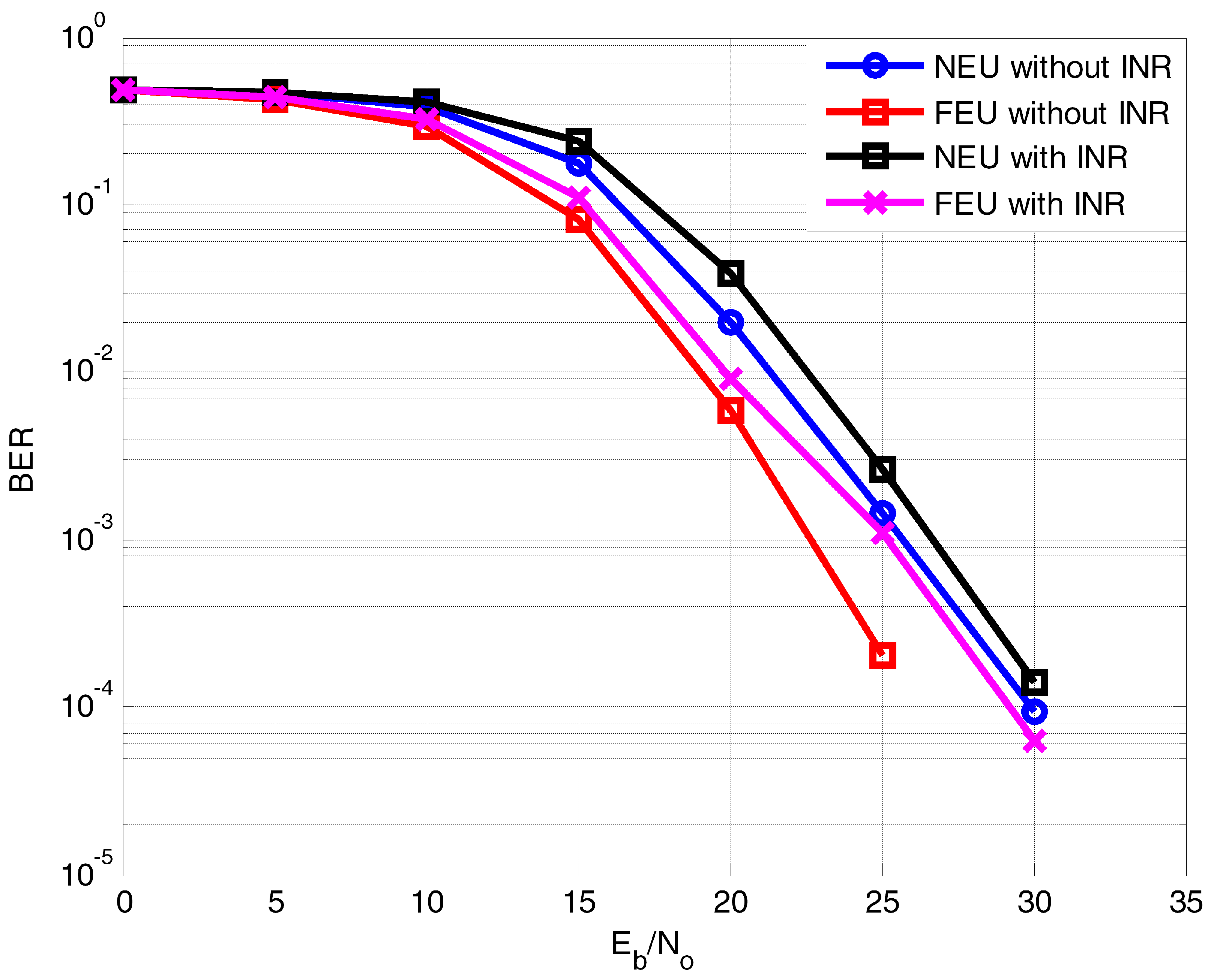
BER Analysis of Coded MC-NOMA

In this section, the BER performance is compared for uncoded MC-NOMA and coded MC-NOMA in the presence of AWGN, impulse noise, and ICI. In the literature [36], the authors claimed that the performance of SIC can be improved by applying channel coding and LP. The proposed system model was also evaluated by varying the noise and interference cell intensities. In Figure 17, the BER comparison of conventional MC-NOMA systems with the coded MC-NOMA system is presented in the presence of a Gaussian channel. The performance of uncoded MC-NOMA and the proposed coded MC-NOMA with its linearly precoded variant was evaluated in the presence of AWGN for both NEU and FEU. Figure 17 shows that for a BER of 10 3 , E b / N o required for MC-NOMA with FDE-SIC is 30 dB for NEU. However, with LP, MC-NOMA with FDE-SIC, the required E b / N o is 25.5 dB; which results in a gain of 4.5 dB. In another comparison for NEU, coded NOMA with FDE also achieved a gain of 4.5 dB over uncoded NOMA for a BER of 10 3 . However, when precoding is applied on coded MC-NOMA with FDE for NEU, the required E b / N o reaches 21 dB; resulting in a gain of 5 dB over coded NOMA-FDE. This better performance of coded NOMA is due to the energy spreading due to WHT.
The performance of uncoded and coded MC-NOMA with and without LP was evaluated in the presence of both AWGN and impulse noise, as shown in Figure 18. Analyzing the performance of the proposed transceiver in the presence of impulse noise is important because in its presence, SIC performance becomes critical as it deteriorates the BER performance for indoor/outdoor mobile communication [37]. For the comparison presented in Figure 18, low-density impulse noise with impulse-noise-index A = 0.1 is introduced. NEU achieves, E b / N o equal to 38.5 dB, 33 dB, and 30 dB for coded MC-NOMA, uncoded MC-NOMA with LP, and coded MC-NOMA with LP, respectively, at a BER of 10 3 , whereas uncoded MC-NOMA is not able to reach at 10 3 . Thus, the proposed coded MC-NOMA with LP obtains a gain of 3 dB and 8.5 dB over uncoded MC-NOMA with LP and coded MC-NOMA without LP. The application of WHT in terms of LP improves the robustness of the system, whereas channel coding also enhances the error correction ability of the system and thus; results in better BER performance.
Moreover, the ideal SIC and code-word-level SIC have almost equal performances. This validates our early assertion regarding the receiver design, as presented in Section 2, where we have also reasoned the same conclusion about the effectiveness of SIC receivers. Similarly, the throughput of the NOMA simulator can be compared with [38], which justifies the improved performance of SIC using the LP method that spreads the information conveyed by symbols into either half of the system or the entire system through the use of various transformations. This also supports the validity of the NOMA simulator. Several papers related to NOMA from our laboratory have been published in recent years [1,23,36,38,40]. Our proposed package can reproduce the majority of the figures in published papers to prove the validity of our simulator.

7. Conclusions

In this paper, we presented the link-level and system-level simulators for SC and MC-NOMA which are believed to be promising candidates for 5G. This is the initial version of the simulator series for NOMA-based systems. The performance of the simulator was evaluated in terms of BER, throughput, spectral efficiency and receiver design. The results provided by our simulator are valid and fully aligned with the results reported in the literature. Future work includes MIMO-based scenarios and MUD techniques other than SIC. In addition, mobility will be added to improve the efficiency of the simulator. Moreover, coded MC-NOMA transceiver design with LP was analyzed in the presence of AWGN, impulse noise, and intercell interference based on the BER performance. Moreover, it is shown that MC-NOMA performs better with the FEC and LP against channel impairments.

Author Contributions

Conceptualization, A.K., M.A.U. and M.R.U.; methodology, A.K.; software, A.K.; validation, A.K., M.A.U., M.R.U., M.A. and S.-Y.S.; resources, S.-Y.S.; writing—original draft preparation, A.K., M.A.U., M.R.U.; writing—review and editing, M.A.; supervision, S.-Y.S.; project administration, S.-Y.S.; funding acquisition, S.-Y.S. All authors have read and agreed to the published version of the manuscript.

Funding

This work was supported by the National Research Foundation of Korea (NRF) grant funded by the Korea government. (MSIT) (No.2019R1A2C1089542).

Conflicts of Interest

The authors declare no conflict of interest. The funder had no role in the design of the study; collection, analyses, or interpretation of data; in the writing of the manuscript, or in the decision to publish the results.

Abbreviations

The following abbreviations are used in this manuscript:
AMCAdaptive Modulation Coding
AWGNAdditive White Gaussian Noise
BSBase Station
BERBit Error Rate
CQIChannel quality indicator
CPCyclic Prefix
FEUFar Equipment User
FDMAFrequency division multiple access
FRAFuture radio access
INRInterference Noise
IEUIntermediate Equipment User
MUDMultiuser detection
MCMulti carrier
MPAmessage passing algorithm
NOMANon-orthogonal multiple access
NEUNear Equipment User
PMIPre-coding matrix indicator
PERPacket Error Rate
QPSKQuadrature phase-shift keying
QAMQuadrature amplitude modulation
SCSuperposition coding
SINRSignal-to-interference noise ratio
SICSuccessive Interference Cancellation
TDMATime division multiple access
UEUser equipment
WHTWalsh Hadamard Transform

References

  1. Khan, A.; Shin, S.Y. Wavelet OFDM-Based Non-Orthogonal Multiple Access Downlink Transceiver for Future Radio Access. IETE Tech. Rev. 2016, 35, 17–27. [Google Scholar] [CrossRef]
  2. Benjebbour, A.; Saito, K.; Li, A.; Kishiyama, Y.; Nakamura, T. Non-orthogonal multiple access (NOMA): Concept, performance evaluation and experimental trials. In Proceedings of the International Conference on Wireless Networks and Mobile Communications (WINCOM), Marrakech, Morocco, 20–23 October 2015; pp. 1–6. [Google Scholar]
  3. Eid, E.M.; Fouda, M.M.; Eldien, A.S.T.; Tantawy, M.M. Performance analysis of MUSA with different spreading codes using ordered SIC methods. In Proceedings of the 2017 12th International Conference on Computer Engineering and Systems (ICCES), Cairo, Egypt, 19–20 December 2017; pp. 101–106. [Google Scholar]
  4. Li, S.; Sun, C.; Jin, X. Research on PDMA Access Technology for 5G Communication. In Proceedings of the 2020 IEEE 20th International Conference on Communication Technology (ICCT), Nanning, China, 28–31 October 2020; pp. 519–523. [Google Scholar]
  5. Kurniawan, D.; Arifianto, M.S.; Kurniawan, A. Low Complexity MIMO-SCMA Detector. In Proceedings of the 2019 IEEE 5th International Conference on Wireless and Telematics (ICWT), Palembang, Indonesia, 27–28 July 2019; pp. 1–5. [Google Scholar]
  6. Wei, Z.; Zhu, X.; Sun, S.; Wang, J.; Hanzo, L. Energy-Efficient Full-Duplex Cooperative Nonorthogonal Multiple Access. IEEE Trans. Veh. Technol. 2018, 67, 10123–10128. [Google Scholar] [CrossRef] [Green Version]
  7. Zeng, H.; Zhu, X.; Jiang, Y.; Wei, Z.; Wang, T. A Green Coordinated Multi-Cell NOMA System With Fuzzy Logic Based Multi-Criterion User Mode Selection and Resource Allocation. IEEE J. Sel. Top. Signal Process. 2019, 13, 480–495. [Google Scholar] [CrossRef]
  8. Haci, H. Non-Orthogonal Multiple Access (NOMA) with Asynchronous Interference Cancellation. Ph.D. Thesis, University of Kent, Canterbury, UK, 2015. [Google Scholar]
  9. Buckheit, J.B.; Donoho, D.L. WaveLab and Reproducible Research. In Handbook of Wavelets and Statistics; Antoniadis, A., Oppenheim, G., Eds.; Springer: New York, NY, USA, 1995; Volume 103, pp. 1–55. [Google Scholar]
  10. Mehlführer, C.; Ikuno, J.C.; Šimko, M.; Schwarz, S.; Wrulich, M.; Rupp, M. The Vienna LTE simulators-Enabling reproducibility in wireless communications research. EURASIP J. Adv. Signal Process. 2011, 2011, 1–14. [Google Scholar] [CrossRef] [Green Version]
  11. Zochmann, E.; Schwarz, S.; Pratschner, S.; Nagel, L.; Lerch, M.; Rupp, M. Exploring the physical layer frontiers of cellular uplink: The Vienna LTE-A Uplink Simulator. EURASIP J. Wirel. Commun. Netw. 2016, 2016, 1–18. [Google Scholar] [CrossRef] [Green Version]
  12. Figueira, J.A.; Sebastião, P.; Cercas, F.; David, N. Modelling and Simulation for Real Scenarios of 4G Mobile Communications Using Google Maps. In Proceedings of the 2013 UKSim 15th International Conference on Computer Modelling and Simulation, Cambridge, UK, 10–12 April 2013; pp. 385–389. [Google Scholar]
  13. Available online: https://www.gl.com/telecom-test-solutions/4G-LTE-communication-network-lab.html (accessed on 8 September 2021).
  14. Ryu, W.J.; Shin, S.Y. Performance evaluation of a power allocation algorithm based on dynamic blocklength estimation for URLLC in the multicarrier downlink NOMA systems. Turk. J. Electr. Eng. Comput. Sci. 2021, 29, 310–320. [Google Scholar] [CrossRef]
  15. Hendraningrat, D.K.; Narottama, B.; Shin, S.Y. Non-orthogonal multiple access in downlink coordinated multipoint transmissions. Phys. Commun. 2020, 39, 101017. [Google Scholar] [CrossRef]
  16. Atmanspacher, H.; Lambert, L.B.; Folkers, G.; Schubiger, P.A. Relevance relations for the concept of reproducibility. J. R. Soc. Interface 2014, 11, 20131030. [Google Scholar] [CrossRef]
  17. Barni, M.; Perez-Gonzalez, F. Pushing science into signal processing. IEEE Signal Process. Mag. 2005, 22, 119–120. [Google Scholar] [CrossRef]
  18. Santiago, R.C.; Szydelko, M.; Kliks, A.; Foukalas, F.; Haddad, Y.; Nolan, K.E.; Kelly, M.Y.; Masonta, M.T.; Balasingham, I. 5G: The Convergence of Wireless Communications. Wirel. Pers. Commun. 2015, 83, 1617–1642. [Google Scholar] [CrossRef] [Green Version]
  19. Su, X.; Yu, H.; Kim, W.; Choi, C.; Choi, D. Interference cancellation for non-orthogonal multiple access used in future wireless mobile networks. Eurasip J. Wirel. Commun. Netw. 2016, 2016, 231. [Google Scholar] [CrossRef]
  20. Rupp, M.; Schwarz, S.; Taranetz, M. The Vienna LTE-Advanced Simulators: Up and Downlink, Link and System Level Simulation; Springer: Singapore, 2016. [Google Scholar]
  21. Vandewalle, P.; Kovačević, J.; Vetterli, M. Reproducible research in signal processing. IEEE Signal Process. Mag. 2009, 26, 37–47. [Google Scholar] [CrossRef] [Green Version]
  22. Khan, A.; Shin, S.Y. Linear Precoding Techniques for OFDM-Based NOMA over Frequency-Selective Fading Channels. IETE J. Res. 2017, 63, 536–551. [Google Scholar] [CrossRef]
  23. Usman, M.R.; Khan, A.; Usman, M.A.; Shin, S.Y. Performance Analysis of Perfect and Imperfect SIC for Downlink Non Orthogonal Multiple Access (NOMA). In Proceedings of the Korean Institute of Communications and Information Sciences, Denpasar, Indonesia, 6–8 October 2016; pp. 176–177. [Google Scholar]
  24. Al-Abbasi, Z.Q.; So, D.K.C. User-pairing based non-orthogonal multiple access (NOMA) system. In Proceedings of the IEEE 83rd Vehicular Technology Conference, Nanjing, China, 15–18 May 2016; pp. 1–5. [Google Scholar]
  25. Saito, Y.; Kishiyama, Y.; Benjebbour, A.; Nakamura, T.; Li, A.; Higuchi, K. Non-orthogonal multiple access (NOMA) for cellular future radio access. In Proceedings of the IEEE 77th Vehicular Technology Conference, Dresden, Germany, 2–5 June 2013; pp. 1–5. [Google Scholar]
  26. Abhay, M. Non-Orthogonal Multiple Access; Seminar Report; Government Engineering College: Thrissur, India, 2017. [Google Scholar] [CrossRef]
  27. Zheng, M.A.; Zhang, Z.Q.; Ding, Z.G.; Fan, P.Z.; Li, H.C. Key techniques for 5G wireless communications: Network architecture, physical layer, and MAC layer perspectives. Sci. China Inf. Soc. 2015, 58, 1–20. [Google Scholar]
  28. Yang, L.; Benjebboiu, A.; Chen, X.; Li, A.; Jiang, H. Considerations on downlink non-orthogonal multiple access (NOMA) combined with closed-loop SU-MIMO. In Proceedings of the 8th International Conference on Signal Processing and Communication Systems, Gold Coast, QLD, Australia, 15–17 December 2014; pp. 1–5. [Google Scholar]
  29. Yan, C.; Harada, A.; Benjebbour, A.; Lan, Y.; Li, A.; Jiang, H. Receiver Design for Downlink Non-Orthogonal Multiple Access (NOMA). In Proceedings of the IEEE 81st Vehicular Technology Conference, Glasgow, UK, 11–14 May 2015; pp. 1–6. [Google Scholar]
  30. Ding, Z.; Yang, Z.; Fan, P.; Poor, H.V. On the performance of non-orthogonal multiple access in 5G systems with randomly deployed users. IEEE Signal Process. Lett. 2014, 21, 1501–1505. [Google Scholar] [CrossRef] [Green Version]
  31. Zhan, Z.; Pang, Z.; Dzung, D.; Xiao, M. Channel Coding for High Performance Wireless Control in Critical Applications: Survey and Analysis. IEEE Access 2018, 6, 29648–29664. [Google Scholar] [CrossRef]
  32. Ding, Z.; Fan, P.; Poor, H.V. Impact of user pairing on 5G non-orthogonal multiple-access downlink transmissions. IEEE Trans. Veh. Technol. 2016, 65, 6010–6023. [Google Scholar] [CrossRef]
  33. Liu, F.; Mahonen, P.; Petrova, M. Proportional fairness- based user pairing and power allocation for non-orthogonal multiple access. In Proceedings of the IEEE 26th Annual International Symposium on Personal, Indoor and Mobile Radio Communications, Hong Kong, China, 30 August–2 September 2015; pp. 1127–1131. [Google Scholar]
  34. Ahmad, M.; Baig, S.; Asif, H.M.; Raahemifar, K. Mitigation of Imperfect Successive Interference Cancellation and Wavelet-Based Nonorthogonal Multiple Access in the 5G Multiuser Downlink Network. Wirel. Commun. Mob. Comput. 2021, 2021, 1–11. [Google Scholar] [CrossRef] [Green Version]
  35. IEEE802. 20 Evaluation Criteria Document. Available online: http://ieee802.org/20/Contribs/C802.20-03-94.pdf (accessed on 6 August 2021).
  36. Usman, M.R.; Usman, M.A.; Shin, S.Y.; Satrya, G.B.; Naqvi, R.A.; Martini, M.G.; Politis, C. Walsh–Hadamard Transform Based Non-Orthogonal Multiple Access (NOMA) and Interference Rejection Combining in Next-Generation HetNets. Mathematics 2021, 9, 348. [Google Scholar] [CrossRef]
  37. Osseiran, A.; Monserrat, J.F.; Marsch, P. 5G Mobile and Wireless Communications Technology; Cambridge University Press: Cambridge, UK, 2016. [Google Scholar]
  38. Khan, A.; Shin, S.Y. Linear precoded wavelet OFDM-based PLC system with overlap FDE for impulse noise mitigation. Int. J. Commun. Syst. 2017, 2017, e3349. [Google Scholar] [CrossRef]
  39. Wang, X.; Poor, H.V. Robust multi-user detection in non-Gaussian channels. IEEE Trans. Signal Process. 1999, 47, 289–305. [Google Scholar] [CrossRef]
  40. Usman, M.R.; Khan, A.; Usman, M.A.; Jang, Y.S.; Shin, S.Y. On the performance of perfect and imperfect SIC in downlink non orthogonal multiple access (NOMA). In Proceedings of the IEEE International Conference on Smart Green Technology in Electrical and Information Systems, Denpasar, Indonesia, 6–8 October 2016; pp. 102–106. [Google Scholar]
  41. Ouyang, X.; Jin, J.; Jin, G.; Li, P. Low complexity discrete hartley transform precoded OFDM system over frequency-selective fading channel. ETRI J. 2015, 37, 32–42. [Google Scholar] [CrossRef]
  42. Qu, L.; He, J.; Assi, C. Understanding the Benefits of Successive Interference Cancellation in Multi-Rate Multi-Hop Wireless Networks. IEEE Trans. Commun. 2014, 62, 2465–2477. [Google Scholar] [CrossRef]
Figure 1. NOMA link-level simulator overall structure.
Electronics 10 02388 g001
Figure 2. NOMA downlink link-level simulator (a) transmitter side; (b) receiver side.
Electronics 10 02388 g002
Figure 3. Block diagram of NOMA system-level Simulator.
Electronics 10 02388 g003
Figure 4. Structure for implementation of a link to system-level Simulator.
Electronics 10 02388 g004
Figure 5. Considered scenarios: (a) 7-cell scenario; and (b) 19-cell scenario.
Electronics 10 02388 g005
Figure 6. Proposed system model for coded MC-NOMA with linear precoding.
Electronics 10 02388 g006
Figure 7. BER comparison of uncoded and coded NOMA for NEU and FEU with perfect SIC in the presence of AWGN and Rayleigh fading channel.
Electronics 10 02388 g007
Figure 8. BER performance comparison of different receivers for NEU and FEU with P 1 , P 2 = 0.1 , 0.9 .
Electronics 10 02388 g008
Figure 9. BER performance comparison of different receivers for NEU and FEU with P 1 , P 2 = 0.2 , 0.8 .
Electronics 10 02388 g009
Figure 10. BER performance comparison of different receivers for NEU and FEU with P 1 , P 2 = 0.3 , 0.7 .
Electronics 10 02388 g010
Figure 11. Throughput performance of un-coded and coded NOMA with perfect SIC in the presence of AWGN and Rayleigh fading channel.
Electronics 10 02388 g011
Figure 12. Capacity performance of the NOMA system.
Electronics 10 02388 g012
Figure 13. Capacity performance of the NOMA system for more than 2 EU (3 EU).
Electronics 10 02388 g013
Figure 14. Seven-cell scenario with intercell interference.
Electronics 10 02388 g014
Figure 15. BER performance comparison of perfect SIC for NEU and FEU in the presence of intercell interference.
Electronics 10 02388 g015
Figure 16. BER performance comparison of perfect SIC for more than 2 users in the presence of intercell interference.
Electronics 10 02388 g016
Figure 17. BER comparison of un-coded MC-NOMA and coded MC-NOMA with and without WHT in the presence of AWGN only.
Electronics 10 02388 g017
Figure 18. BER comparison of un-coded MC-NOMA and coded MC-NOMA with and without WHT in the presence of AWGN and impulse noise.
Electronics 10 02388 g018
Table 1. Link-level and system-level parameters for exemplary results.
ParametersValueParametersValues
Cells 7 , 19 Thermal noise 174 dBm/Hz
Antenna Config. 1Tx, 2RxIntercell interferenceOne-tier, two-tier
Cell Radius500 mChannel EqualizationFDE-MMSE
Intersite distance1 kmModulation schemeBPSK, QPSK, 16QAM
Interuser interferenceNonePower Allocation P 1 = (0.1–0.3), P 2 = (0.9–0.7)
NoiseAWGNInterference CancellationPerfect, Iterative
UEs/cell 2 , 3 Synchronizationideal
Multiplexed UEs/Cell 2 , 3 Channel EstimationIdeal
Carrier frequency2 GHzCyclic Prefix20%
System BW20 MHzUE Noise9 dB
Table 2. System parameters for 7-cell scenario.
ParameterValue
Intercell Interference (ICI), Inter user Interference (IUI)None (Initially)
Intersite distance1 km
Inter user distance400 m, 300 m, 200 m
Cell Radius500 m
Distance between BS and FEU450 m, 400 m, 350 m
Distance between BS and NEU50 m, 100 m, 150 m
Table 3. System Parameters for 7-cell Scenario.
Cell No.Distance between Users from Their
Corresponding BS in Each Cell
Distance between Neighboring
Cell Users and Center Cell BS
1FEU: 450 m, NEU: 50 mNEU: 1050 m, FEU: 950 m
2FEU: 400 m, NEU: 100 mNEU: 1000 m, FEU: 700 m
3FEU: 350 m, NEU: 150 mNEU: 950 m, FEU: 750 m
4FEU: 450 m, NEU: 50 mNEU: 950 m, FEU: 1100 m
5FEU: 400 m, NEU: 100 mNEU: 950 m, FEU: 1300 m
6FEU: 350 m, NEU: 50 mNEU: 1050 m, FEU: 1250 m
Publisher’s Note: MDPI stays neutral with regard to jurisdictional claims in published maps and institutional affiliations.

