1. Introduction
The magnetic materials are essential for the magnetic energy storage of various applications such as power converters and wireless power transfer systems. As low operating frequency applications (50 Hz/60 Hz), silicon steel sheet materials are widely used for the utility transformers or pole transformers in various industries [
1]. On the other hands, most electric devices are designed based on the high-frequency magnetic materials, operating at several tens of
kHz high operating frequency, for compact size of the magnetic components [
2,
3]. In general, high-frequency ferrite cores are highly preferred due to high-frequency characteristics, low core loss, and easy manufacturing [
3]. Recently, amorphous cores, which are formed by multi layers of laminated cores, are also the alternative solutions for 60 Hz–100
kHz of operating frequency applications [
4]. Such amorphous cores have a high saturated magnetic field
Bsat (≈1.5 T) and can reduce the eddy loss due to ultra-thin-laminated Fe-based plates [
1,
4]. In order to miniaturize the magnetic materials, Nanocrystalline alloy, which is usually composed of Fe, Si, B with the other chemical combinations, can be utilized over 1
kHz–100
kHz of operating frequency applications [
5]. Such magnetic materials mentioned above have their own merits and demerits for various applications. Thus, by referring to inherent magnetic characteristics of the magnetic materials, the most appropriate magnetic materials should be selected, according to the operating frequency of its applications.
In order to design the magnetic components applied to industrial applications, the major characteristics of the magnetic materials, e.g., saturated magnetic flux density, initial permeability, Curie temperature, power loss [
mW/cm
3], etc., should be analyzed. As one of the important factors, the permeability is the baseline design parameter to determine the size of the magnetic components and analyze the core loss [
1,
2,
3,
4,
5,
6,
7]. Although the major characteristics of the selected magnetic cores were already described in datasheets, the complex permeability characteristics w.r.t. the operating frequency need to be further investigated, if the permeability is not revealed in detail. Especially, imaginary permeability, which implies the core loss, is not usually described in datasheets; hence, investigating the imaginary permeability becomes important for estimating the core loss and managing the heat dissipation of the magnetic core. As the typical methods to investigate the complex permeability, high resolution based LCR meters for
kHz ranges [
7], microwave generators for MHz-GHz [
8], vector network analyzers (VNA) for GHz ranges [
9,
10,
11], and millimeter-wave spectrometers for GHz ranges [
12] could be utilized to derive the complex permeability as well as inductance and resistance. Although several special measurement methods to investigate the complex permeability have been presented for various purposes, e.g., ultra-wideband permeability measurements [
8], transmission bridge method [
9], and using rod samples inside a rectangular waveguide [
10], they are limited to be used for millimeter-wave frequency ranges. Because such measurement devices cannot provide appropriate AC test current levels [
7,
8,
9,
10,
11,
12,
13], the measurement results of the complex permeability may not be accurate for the specified frequency ranges; hence, they are not suitable for the general magnetic components applied in power applications due to extremely low AC test currents in magnetic components. Furthermore, the previous literatures mentioned above require complicated experimental environments, which make the power engineers difficult to investigate the major characteristics of the magnetic materials. For this reason, an appropriate AC power supply based complex permeability measurement is required so that appropriate AC test current is applied to the magnetic components [
14].
In this paper, a simple but useful calculation methodology to find the complex permeability is proposed. The complex permeability is composed of real permeability for the size of the magnetic core and imaginary permeability for the core loss. By virtue of the proposed calculation methodology of complex permeability, the real permeability μr′ and imaginary permeability μr″ can be specified w.r.t. the operating frequency. To evaluate a comparative analysis of different magnetic materials, a ferrite core, an amorphous core, and a nanocrystalline core have been selected and verified by experiments. By virtue of the proposed calculation methodology for the complex permeability, the major characteristics of the magnetic materials for the design of the magnetic components can be found for a wide operating frequency range.
2. Proposed Calculation Methodology of the Complex Permeability
According to the datasheet of the PM11 ferrite core used in this paper, the real permeability is well described w.r.t different
fs. However, the imaginary permeability, which is related to the core loss resistance, is not described below
fs = 250
kHz from the PM11 datasheet [
15]. For this reason, in order to exactly find the value of imaginary permeability of PM11 for
fs < 250
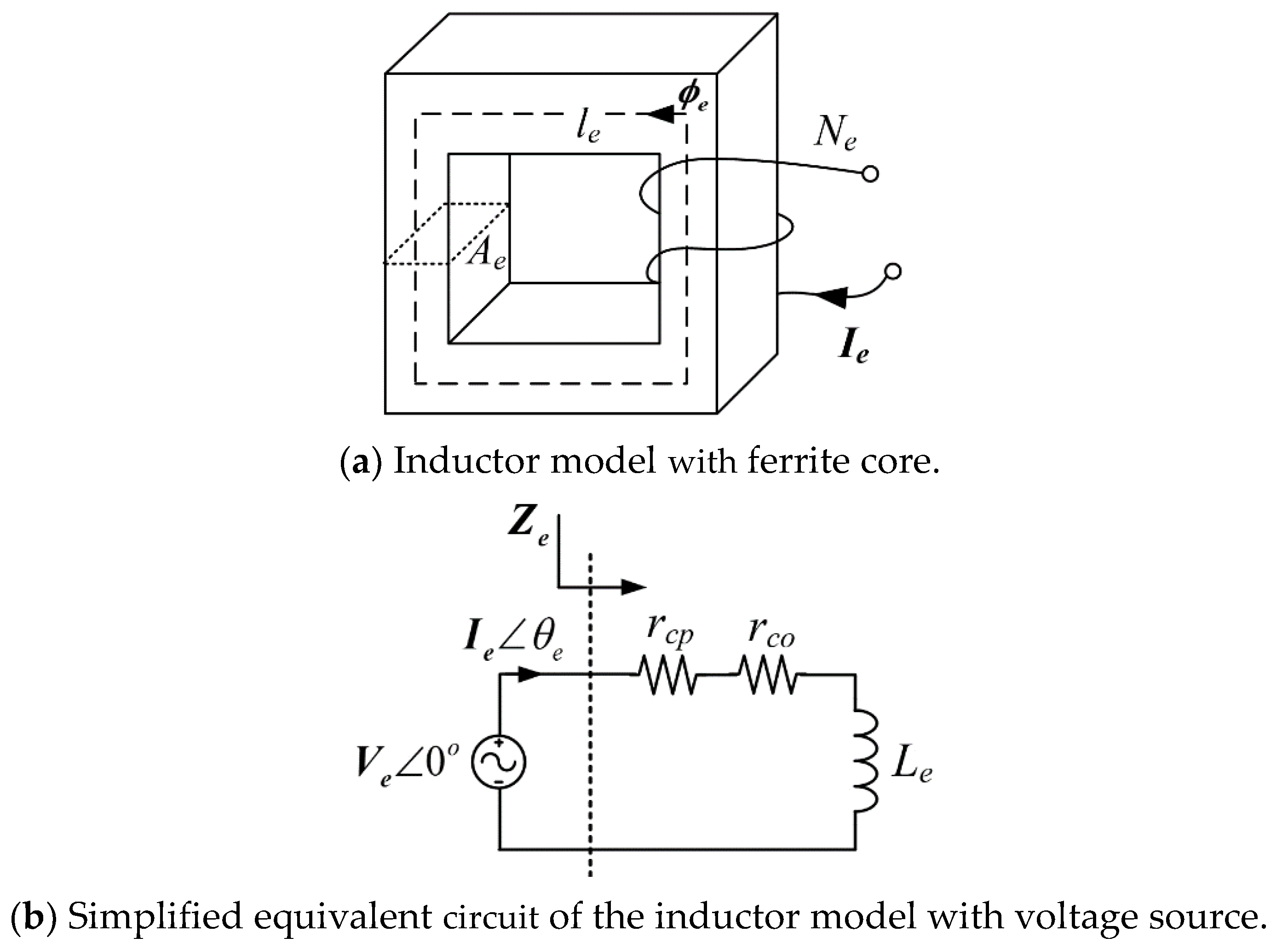
kHz, a simple inductor model with a ferrite core has been built, as shown in
Figure 1a. A simplified equivalent circuit of
Figure 1a is shown in
Figure 1b, where the voltage source is connected to the inductor model in series to evaluate the characteristics of the inductor model. For simplicity of analysis, all the magnetic field is assumed to be in the magnetic core in this paper. In
Figure 1b, the complex impedance of the inductor model
Ze can be defined as follows:
where
fs is the operating frequency, and
ωs is the angular switching frequency. Bold characters mean a complex value.
Ze and
Le are the complex values for the impedance and inductance, and
rcp is the copper loss-term resistance including the skin effect and eddy effect determined by frequency. From (1b), the complex inductance
Le includes core loss resistance
rco because
rco depends on the magnetic characteristics [
6].
To calculate the inductance in terms of the physical dimensions of the inductor model in
Figure 1a, the complex inductance
Le can be expressed by the complex permeability as follows:
where
Ae and
le are effective magnetic area and effective magnetic path length, respectively.
From (1) and (2), the real and imaginary permeability can be found as follows:
From (3), the real permeability is proportional to the inductance Le and the imaginary permeability is proportional to the core loss resistance rco.
A function generator to provide a high-frequency voltage source
Ve is used, as shown in
Figure 1b. Depending on the electrical and magnetic characteristics of the inductor model, test current
Ie and phase difference between the voltage and current
θe are different as follows:
where such
Ie and
θe can be measured by an oscilloscope, and
rcp can be found by measuring only the copper wire resistance without the ferrite core.
Based on the measured results of
Ve,
Ie and
θe, the values of
Le and
rcp can be obtained as follows:
Based on the calculated results in (5), the real and imaginary permeability can be calculated from (3). Contrary to the conventional complicated methods [
8,
9,
10,
11,
12], the suggested (1)–(5) are so simple and intuitive; thus, the real and imaginary permeability can be easily and immediately found by simple test prototypes in
Figure 1.
3. Experimental Verification
In order to identify the real and imaginary permeability of the magnetic cores and to evaluate the comparative analysis for different magnetic cores, test prototypes for the inductor have been built, as shown in
Figure 2. Physical parameters of
Ae,
le, and
Ne in
Figure 1 were arbitrarily selected based on a piece of magnetic core, commercially available in markets:
Ae is magnetic flux area,
le is the length of effective magnetic path, and
Ne is the number of winding turns. The physical parameters are summarized in
Table 1. A PM11 magnetic material from TODAISU has been selected for Mn-Zn-type ferrite core [
15]. The AMLB-8320 amorphous core from AMOGREENTECH, which is formed by layers of laminated 40-µm-thin amorphous-metal-film, has been selected for the amorphous core, as shown in
Figure 2b. A VITROPERM 500F core from VACUUMSCHMELZE has been selected for the Nanocrystalline core, as shown in
Figure 2c [
16]. Considering the applicable operating frequency of kHz ~ several MHz for three major magnetic materials, e.g., ferrite core, Amorphous core, and Nanocrystalline core in this paper, 1 kHz to 1 MHz frequency range has been specified.
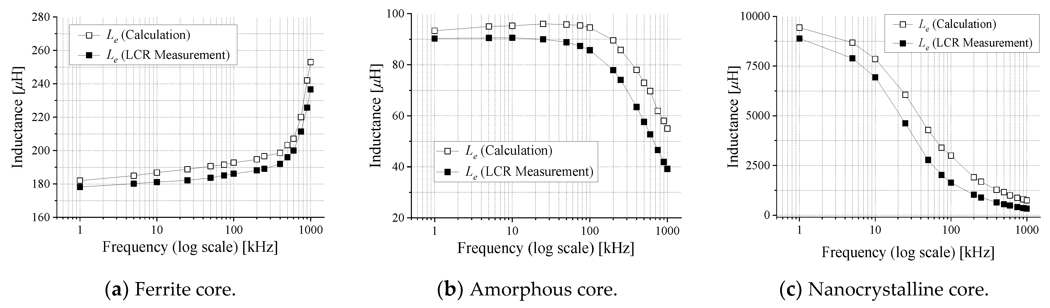
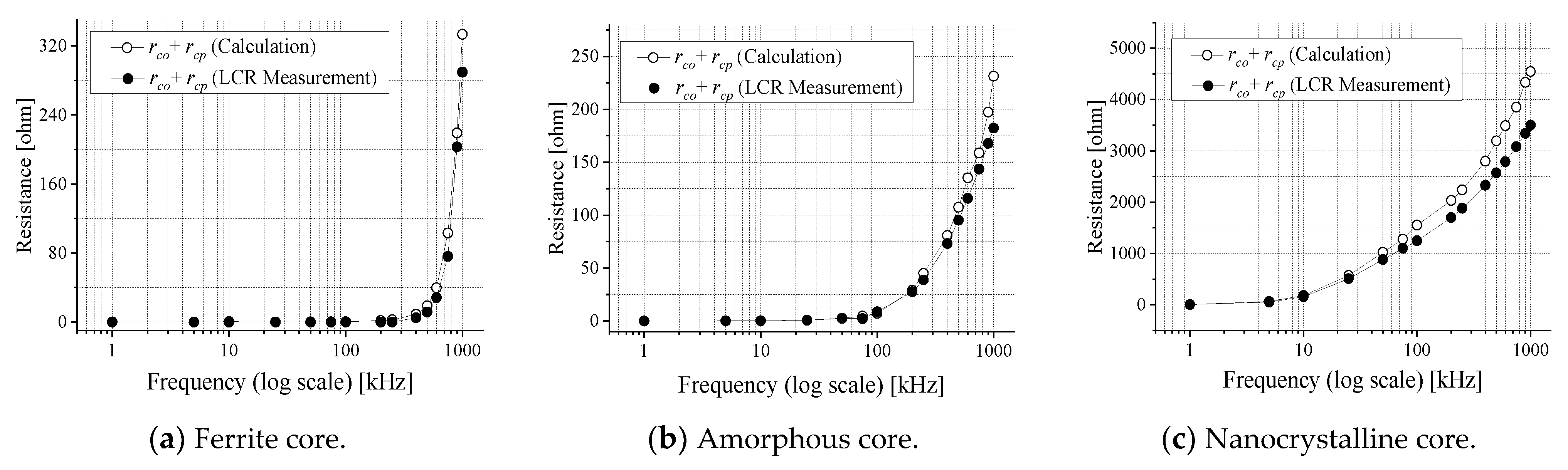
Based on the measurement results of
Ve,
Ie, and
θe in (4) by a function generator (KEYSIGHT 33522A) and an oscilloscope (Lecroy 104Xi-A oscilloscope), the inductance and resistance in (5) w.r.t. operating frequency can be calculated, as shown in
Figure 3 and
Figure 4, where LCR measurement results have been obtained by a KEYSIGHT network analyzer E5071C. In case of LCR measurement used in this paper, uncertainty below a 10 MHz frequency range is highly less than 0.1(dB) [
17,
18]. A little discrepancy between calculation and LCR measurement, i.e., lower than 8%, comes from leakage magnetic flux, which is leaking out to the air, not circulating through the test prototypes of the magnetic materials in
Figure 2. Because the proposed idea to calculate the inductance and resistance in (1)–(5) is assumed to be ideal inductor having no leakage magnetic flux, this inherent leakage magnetic component is not reflected to the calculated results of
Figure 3 and
Figure 4. Unfortunately, this leakage component cannot be analytically modeled due to the unpredictable radiation of the magnetic field and the non-linear property of the ferrite core [
3]. This leakage magnetic flux could be minimized if a manufactured piece of the magnetic core in
Figure 2 is small enough so that the generated magnetic flux from the test currents is all passing through the magnetic cores, not leaking to the air. Because the manufactured pieces of the magnetic cores in
Figure 2 are the commercialized products in markets, and the size of magnetic pieces are already fixed, this small discrepancy is inevitable in this case. Nevertheless, the confirmation of the tendency for the permeability w.r.t. operating frequency is highly similar, and the relative comparison w.r.t. operating frequency can be obtained by the proposed idea. The real permeability of the ferrite core increases w.r.t. frequency, whereas that of the amorphous core and nanocrystalline core decreases. The imaginary permeability always increases for three core cases due to the increment of the core loss, which is usually proportional to the operating frequency.
From the results of
Figure 3 and
Figure 4, the real and imaginary permeability can be found, as shown in
Figure 5. In case of the PM11 ferrite core, the calculated results of the real and imaginary permeability w.r.t. frequency are shown in
Figure 5a. The values of real and imaginary permeability for
fs > 250
kHz, which were already described in the datasheet [
15], are matched well with the calculation and measurement results. According to the datasheet [
15], unfortunately, the information for the imaginary permeability has not been revealed for the
fs < 250
kHz range. From the matching tendency between datasheet and calculation results, it can be said that the values of real and imaginary permeability for
fs < 250
kHz is reliable. Although the magnetic characteristic of the amorphous core is not revealed, the real and imaginary permeability can be found by the proposed methodology, as shown in
Figure 5b. In case of the nanocrystalline core, the calculation results are also in good agreement with the datasheet that has described only the tendency of the permeability w.r.t. the operating frequency [
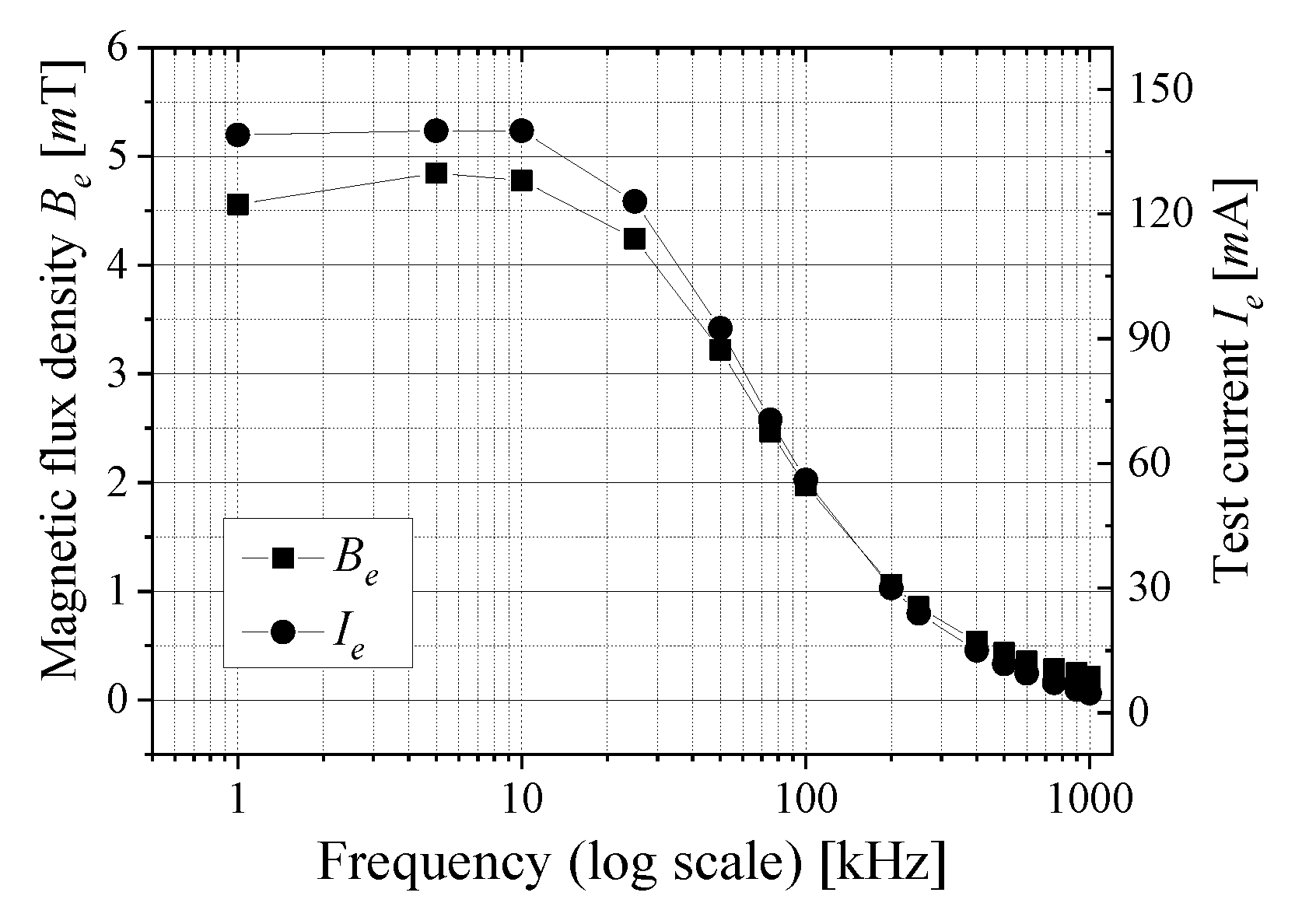
16]; hence, the numerical values for the permeability can be specified. The test current level
Ie and the calculated magnetic flux density inside the ferrite core
Be w.r.t. the operating frequency is shown in
Figure 6. The magnetic field inside the magnetic cores
Be can be calculated from (2), and the cases of amorphous core and nanocrystalline core are omitted due to the same tendency of
Figure 6. It is noteworthy that the test currents and magnetic flux density can be increased until
Be <
Bsat ≈ 0.3 T by the other AC power supply devices, so that the exact complex permeability can be obtained under rated operating condition, although the function generator, which can provide a convenient frequency modulation function, has been used in this paper.
All the calculated results w.r.t. the different operating frequency are summarized in
Table 2. Magnetic loss tangent
tan δμ is defined as
μ″/
μ′, which represents the magnetic core loss and can be usefully utilized for a finite-element-method (FEM) simulation analysis [
3]. Magnetic loss tangent δ
μ in
Table 2 is essential to specify the core loss resistance modeling from the 3D FEM simulation analysis [
2,
3]. Based on the core loss resistance obtained by magnetic loss tangent δ
μ, the static core loss resistance can be obtained to analyze the core loss of the magnetic components for power converters and wireless power transfer systems. According to the results of
tan δμ in
Table 2, the ferrite core is superior to the amorphous core and nanocrystalline core for coil loss term. The complex permeability of the amorphous core is relatively lower than the others. The nanocrystalline core has very high real permeability, i.e., the core can be highly minimized. However, the imaginary permeability is also very high, i.e., the nanocrystalline core is of inferior core efficiency, although the magnetic component can be minimized by the nanocrystalline core. From the measured results in
Table 2, the core loss of amorphous core may be almost 2.7 times larger than that of ferrite core at
fs = 10
kHz under the same physical and operating conditions. If the operating frequency increases, the loss gap significantly increases. Therefore, in terms of the low core loss and high-frequency characteristics, the ferrite core is recommended. On the other hand, the nanocrystalline core is recommended for compact magnetic core. According to the magnetic results obtained by the proposed calculation methodology, the optimal magnetic core can be appropriately selected at the specified operating frequency condition.


