Article

FPGA Implementation of the Range-Doppler Algorithm for Real-Time Synthetic Aperture Radar Imaging

1
School of Electronics and Information Engineering, Korea Aerospace University, Goyang-si 10540, Korea
2
Department of Smart Drone Convergence, Korea Aerospace University, Goyang-si 10540, Korea
*
Author to whom correspondence should be addressed.
Electronics 2021, 10(17), 2133; https://doi.org/10.3390/electronics10172133
Submission received: 8 July 2021 / Revised: 12 August 2021 / Accepted: 24 August 2021 / Published: 2 September 2021
(This article belongs to the Special Issue System-on-Chip (SoC) Design and Its Applications)

Abstract

:
In this paper, we propose a range-Doppler algorithm (RDA)-based synthetic aperture radar (SAR) processor for real-time SAR imaging and present FPGA-based implementation results. The processing steps for the RDA include range compression, range cell migration correction (RCMC), and azimuth compression. A matched filtering unit (MFU) and an RCMC processing unit (RPU) are required for real-time processing. Therefore, the proposed RDA-based SAR processor contains an MFU that uses the mixed-radix multi-path delay commutator (MRMDC) FFT and an RPU. The MFU reduces the memory requirements by applying a decimation-in-frequency (DIF) FFT and decimation-in-time (DIT) IFFT. The RPU provides a variable tap size and variable interpolation kernel. In addition, the MFU and RPU are designed to enable parallel processing of four 32-bit which are transferred via a 128-bit AXI bus. The proposed RDA-based SAR processor was designed using Verilog-HDL and implemented in a Xilinx UltraScale+ MPSoC FPGA device. After comparing the execution time taken by the proposed SAR processor with that taken by an ARM cortex-A53 microprocessor, we observed a 85-fold speedup for a 2048 × 2048 pixel image. A performance evaluation based on related studies indicated that the proposed processor achieved an execution time that was approximately 6.5 times less than those of previous FPGA implementations of RDA processors.

1. Introduction

A synthetic aperture radar (SAR) is an active sensor system that operates in the microwave band. The primary strength of the SAR is that it can provide high-quality images independently of light and weather conditions [1,2,3,4]. Traditional SAR systems have been limited to being mounted on large platforms, such as satellites and aircraft, because of their high power consumption and the processing requirements of large datasets. However, recent advances in CMOS process technologies and signal processing have enabled the development of compact and lightweight SAR systems, and research on SAR systems mounted on small platforms, such as unmanned aerial vehicles (UAVs), is increasing [5,6,7,8,9,10,11,12,13,14,15].
SAR data processing is computationally intensive, and hardware accelerators, such as graphics processing units (GPUs) and field programmable gate arrays (FPGAs), are required for real-time processing [16,17,18,19,20,21,22,23,24,25,26]. Although GPUs have high processing capabilities, their large power consumption makes them unsuitable for small platforms. FPGAs have made significant progress in terms of high throughput, on-chip storage resources, arithmetic logic resources, and low power consumption [27,28]. Therefore, an FPGA-based SAR system is appropriate for a small platform with limited power. Several SAR imaging algorithms have been implemented, including the range-Doppler algorithm (RDA) [17,18,19], back-projection algorithm (BPA) [20,21,22], and polar format algorithm (PFA) [23,24,25,26]. Although these algorithms are effective, RDA is the most popular one because it is simple, offers easy motion compensation, and provides a flexible tradeoff between accuracy and the number of computations [29]. RDA contains three primary stages: range compression, range cell migration correction (RCMC), and azimuth compression [30,31,32]. Range compression and azimuth compression are also known as range-matched filtering and azimuth-matched filtering, respectively, and they are both performed via multiplication in the frequency domain. Efficient transformation of signals to and from the frequency domain is achieved using the fast Fourier transform (FFT). Meanwhile, RCMC is realized via sinc interpolation [33,34]. Therefore, the FFT and interpolation processors are the two key components in the implementation of an RDA.
In the RDA, the azimuth resolution depends on the FFT length [35]. FFT processors for the RDA typically support a fixed length, making it challenging to apply this algorithm in various SAR applications. Therefore, a variable-length FFT processor is required [36]. Many FFT algorithms are available, including radix-2, radix-4, radix-8, radix- 2 2 , radix- 2 3 , and mixed-radix. The mixed-radix algorithm can reduce the number of non-trivial multiplications better than the radix-2 or radix-4 algorithms can. Trivial multiplication can be simply implemented by using shifters and adders, and therefore, its complexity is much lower than that of non-trivial multiplication. Therefore, the mixed-radix algorithm can be implemented with lower complexity than the radix-2 or radix-4 algorithms can [37]. In addition, it can support more flexible FFT lengths than the radix-4 or radix-8 algorithms, and is has double the throughput of the radix- 2 3 algorithm. It is also suitable as an area-efficient variable-length FFT processor [38,39].
FFT hardware architectures can be roughly classified as single-butterfly, pipeline, and parallel architectures. In particular, the pipeline architecture offers an appropriate tradeoff between hardware complexity and throughput. Pipeline architectures are classified as single-path delay feedback (SDF) and multi-path delay commutator (MDC) architectures. The SDF architecture operates at a lower throughput than the MDC architecture because of its single path [40]. In a real-time SAR system, an FFT processor should provide high throughput rates. Therefore, the MDC architecture is more appropriate than the SDF architecture in such systems [41,42].
The tap size of the interpolation processor in the RDA depends on the quality of the RCMC. Although a longer tap provides higher accuracy, the computational complexity increases with the tap size. Analogously, a short tap size implies low computational complexity but low accuracy. Because the required accuracy and computational complexity vary between SAR applications, the tap size should ideally be variable so that the interpolation processor is suitable for various SAR applications. Interpolation processors generally use several types of windows, such as the Kaiser, Hamming, and Hanning windows, to reduce the sidelobes of the sinc kernel. Because different windowed sinc kernels offer different tradeoffs between sidelobes and resolution, an appropriate windowed sinc kernel must be selected for each SAR application [35]. In addition, interpolation operations must be accelerated through parallel processing because of their high computational complexity.
Many studies have been conducted to implement RDA using FPGAs. Araujo et al. used an Altera Cyclone E IV FPGA to implement the RDA with a mixed-radix SDF FFT processor, and RCMC was implemented using a data-shifting method. This FPGA acquired a 2048 × 2048 pixel image in 20.31 s at a speed of 130 MHz [17]. Hou et al. used a Xilinx Virtex-6 FPGA to implement the RDA with a radix-2 single-butterfly FFT processor. It acquired a 2048 × 4096 pixel image in 12.03 s at a speed of 200 MHz [18]. In addition, Hossain et al. used a Xilinx Virtex-6 FPGA to implement the RDA with a radix-2 SDF FFT processor. It acquired a 2048 × 900 pixel image in 2.08 s at a speed of 200 MHz [19].
In this study, we propose an RDA-based SAR processor containing a matched filtering unit (MFU) using a mixed-radix multi-path delay commutator (MRMDC) FFT processor and an RCMC processing unit (RPU). The MRMDC FFT processor supports variable length and offers a high throughput and low area. The MFU reduces the memory requirements by applying the decimation-in-frequency (DIF) FFT and decimation-in-time (DIT) IFFT so that the FFT processor’s output data are entered into the IFFT processor without reordering. The RPU provides a 2/4/6/8/10/12/14/16 variable tap size, variable interpolation kernel suitable for various SAR applications, and parallel architecture. In summary, the main contribution of this study is the proposal of a high-speed and area-efficient hardware structure for designing an RDA-based SAR processor and the presentation of its implementation and experimental results.
The remainder of this paper is organized as follows. Section 2 reviews the RDA. Section 3 describes the hardware architecture of the proposed RDA-based SAR processor. Section 4 presents and discusses the implementation and verification results, and also compares the speed performance of the proposed processor with results from previous studies. Section 5 concludes the paper.

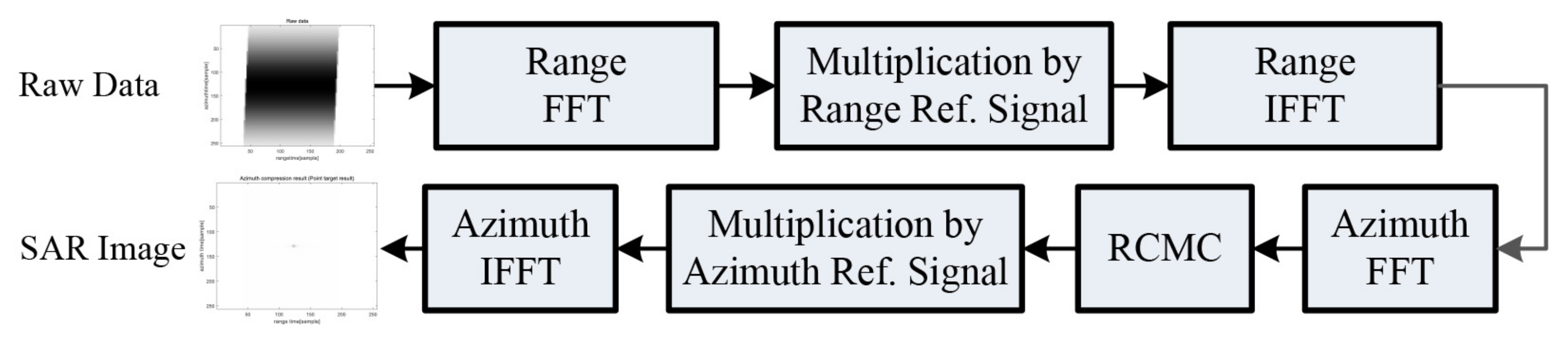
2. Range-Doppler Algorithm

A procedure of the RDA is shown in Figure 1. The RDA comprises three processing steps: range-matched filtering, RCMC, and azimuth-matched filtering. Range-matched filtering is performed on raw data, which are multiplied by the range reference signal after the range FFT. The range IFFT is then performed. The RDA obtains low-quality SAR images owing to relative motion between the radar and target. Therefore, to obtain high-quality SAR images, signals from the same scatter should be arranged in one range cell. This operation is called RCMC. Before proceeding with RCMC, however, the azimuth FFT must be performed. Finally, SAR image generation is complete once azimuth-matched filtering is performed via multiplication by the azimuth reference signal in the azimuth frequency domain, followed by the azimuth IFFT.
The transmission signal of a pulse-Doppler radar is assumed to be a linear frequency modulation (FM) chirp signal with an FM rate of K r . The received signal is demodulated into a baseband and can be described as
s 0 τ , η = A 0 w r τ R ( η ) w a η η c e x p j 2 π f 0 R ( η ) + j π K r τ R ( η ) 2
where A 0 is the amplitude of the signal, R ( η ) is equivalent to 2 R ( η ) / c , c is the velocity of light, τ is the range time, η is the azimuth time, η c is the beam center crossing time, w r ( τ ) is the range envelope (a rectangular function), w a ( η ) is the azimuth envelope (a sinc-squared function), f 0 is the radar center frequency, K r is the range chirp FM rate, and R ( η ) is the instantaneous slant range. The discrete-time expression of Equation (1) is given by
s 0 n , k = A 0 w r n R ( k ) w a k k c e x p j 2 π f 0 R ( k ) + j π K r n R ( k ) 2
where n is the range time index ( τ = n T s ) and T s is the sampling interval. k is the azimuth time index ( η = k T p ) and T p is the pulse-repetition time. Let S 0 ( f n , k ) be the range Fourier transform of s 0 ( n , k ) from Equation (2) and let G ( f n ) be the frequency-domain range reference signal. The output of the range-matched filter can be described as
s r c n , k = I F F T n S 0 f n , k G f n = A 0 p r n R ( k ) w a k k c e x p j π R ( k ) λ
where p r is the range envelope (a sinc function), λ is the wavelength, I F F T n is the range IFFT, and 2 R ( k ) / c is the target range migration incorporated via the azimuth time. The range-matched filtered signal requires the azimuth FFT for RCMC and azimuth-matched filtering. In low-squint cases, the range equation can be approximated using Equation (4).
R k = R 0 2 + V r 2 k 2 R 0 + V r 2 k 2 2 R 0
where R 0 is the slant range of the closest approach, and V r is the platform velocity. By substituting R ( k ) in the phase component of Equation (3) for the range-matched filtered signal, Equation (5) can be obtained as
s r c n , k A 0 p r n 2 R ( k ) c w a k k c e x p j 4 π f 0 R 0 c e x p j π 2 V r 2 λ R 0 k 2
Because the phase in Equation (5) is a function of k 2 , the signal has linear FM characteristics in the azimuth direction, and the azimuth FM rate can be expressed as
K a 2 V r 2 λ R 0
By substituting Equation (6) into Equation (5), the signal after the azimuth FFT can be rewritten as
S 1 n , f k = A 0 p r n 2 R r d ( f k ) c W a f k f k c e x p j 4 π f 0 R 0 c e x p j π f k 2 K a
where W a ( f k ) is the frequency-domain version of the azimuth beam pattern w a ( k ) . The first phase term carries the inherent phase information of the target and is not important in an intensity image. The second phase term represents the azimuth modulation. The range cell migration (RCM) in the range time and azimuth frequency domain R r d ( f k ) can be expressed as
R r d f k R 0 + V r 2 2 R 0 f k K a 2 = R 0 + λ 2 R 0 f k 2 8 V r 2
RCMC is performed via sinc interpolation in the range direction. The sinc kernel is weighted by a tapering window, such as the Kaiser, Hamming, or Hanning windows. The second term in Equation (8) represents the amount of RCM to be corrected, expressed as
Δ R f k = λ 2 R 0 f k 2 8 V r 2
The signal after the RCMC operation can be expressed as
S 2 n , f k = A 0 p r n 2 R 0 c W a f k f k c e x p j 4 π f 0 R 0 c e x p j π f k 2 K a
The range envelope p r is independent of f k , indicating that the RCM has been corrected. In addition, the energy is arranged at n = 2 R 0 / c , which is the range of the closest approach. To perform multiplication by the azimuth reference signal, the signal after RCMC, i.e., S 2 ( n , f k ) in Equation (10), is multiplied by the frequency-domain azimuth reference signal H a z ( f k ) . The azimuth reference signal can be expressed as
H a z f k = e x p j π f k 2 K a
The frequency-domain azimuth reference signal can be obtained as a complex conjugate of the second phase term of Equation (10), where K a is a function of R 0 . The resulting signal after azimuth reference multiplication can be expressed as
S 3 n , f k = S 2 n , f k H a z ( f k ) = A 0 p r n 2 R 0 c W a f k f k c e x p j 4 π f 0 R 0 c
Finally, the RDA values are obtained by performing an azimuth IFFT on Equation (12), expressed as
s a c n , k = I F F T k S 3 n , f k = A 0 p r n 2 R 0 c p a k e x p j 4 π R 0 λ + j 2 π f k c k
where p a is a sinc-like azimuth envelope. In Equation (13), the range envelope and azimuth envelope indicate that the target is now positioned at n = 2 R 0 / c and k = 0 .

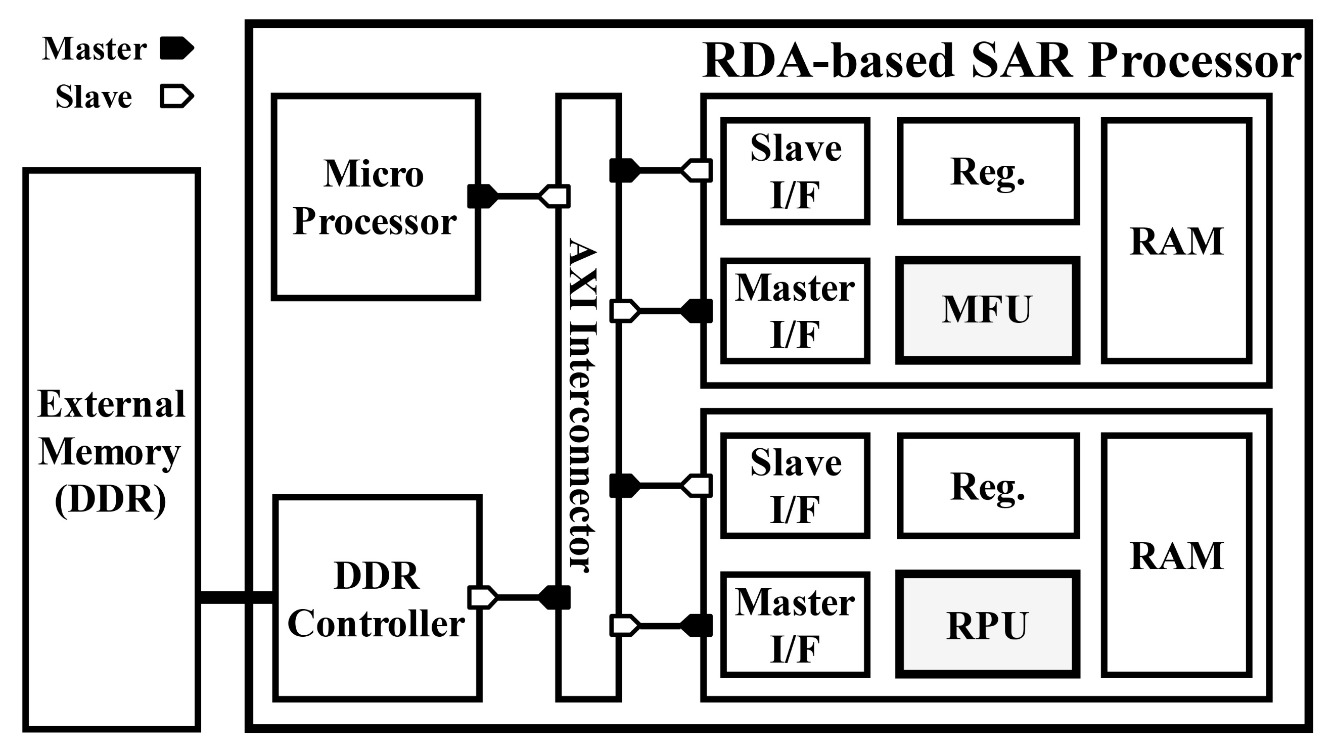
3. Proposed Hardware Architecture

Figure 2 shows the hardware architecture of the proposed RDA-based SAR processor, which contains an MFU in order to perform the range-matched filtering, azimuth-matched filtering, and azimuth FFT, as well as an RPU to correct the RCM. The MFU and RPU comprise master and slave interfaces for communicating with the double-data-rate (DDR) memory controller and microprocessor, respectively, a register for changing the operation mode of each unit, and a cache RAM for temporarily storing input/output data. In our design, the master interfaces are connected to the DDR memory controller via a 128-bit AXI bus. Thus, we can transmit four 32-bit data per clock cycle. Therefore, the MFU and RPU can efficiently perform parallel operations on the four 32-bit data. To achieve this, the FFT included in the MFU was designed with an MRMDC architecture, and the RPU was designed with an architecture comprising four interpolation modules.

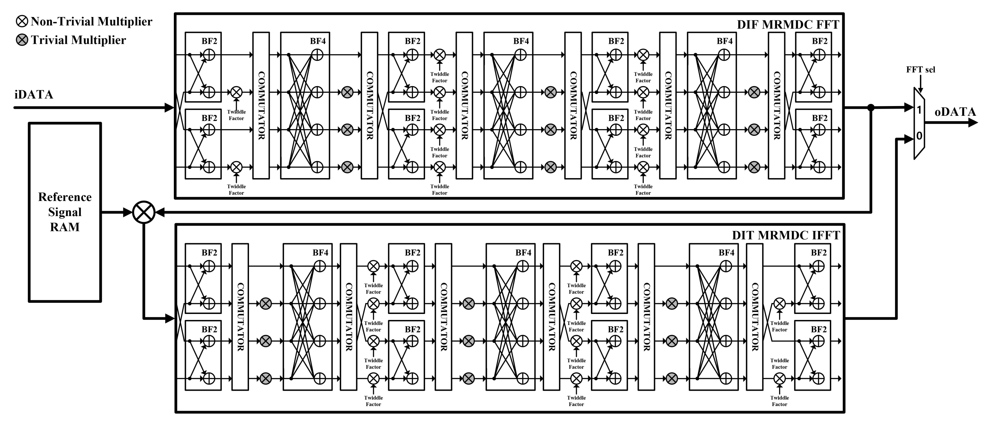
3.1. Matched Filtering Unit (MFU)

The proposed MFU consisted of a DIF MRMDC FFT module, DIT MRMDC IFFT module, and reference signal RAM, as shown in Figure 3. The reference signal RAM stored reference signals in the frequency domain for range- and azimuth-matched filtering. The DIF MRMDC FFT and DIT MRMDC IFFT modules employed a mixed-radix FFT algorithm to support flexible FFT lengths and to reduce the number of non-trivial multipliers, thereby facilitating a low-area implementation. The FFT modules employed the MDC architecture to enable high-throughput processing of four 32-bit data per clock cycle. In particular, the FFT and IFFT modules applied the DIF and DIT algorithms, respectively, so that the FFT module output could be used as an input to the IFFT module without reordering. This reduced the memory requirements and reordering time by eliminating the need for a reordering buffer. In addition, the MFU was designed to enable the azimuth FFT operation before RCMC by allowing it to output to the DIF MRMDC FFT module according to the slave register setting. In such cases, FFT reordering was performed while writing to the cache RAM.

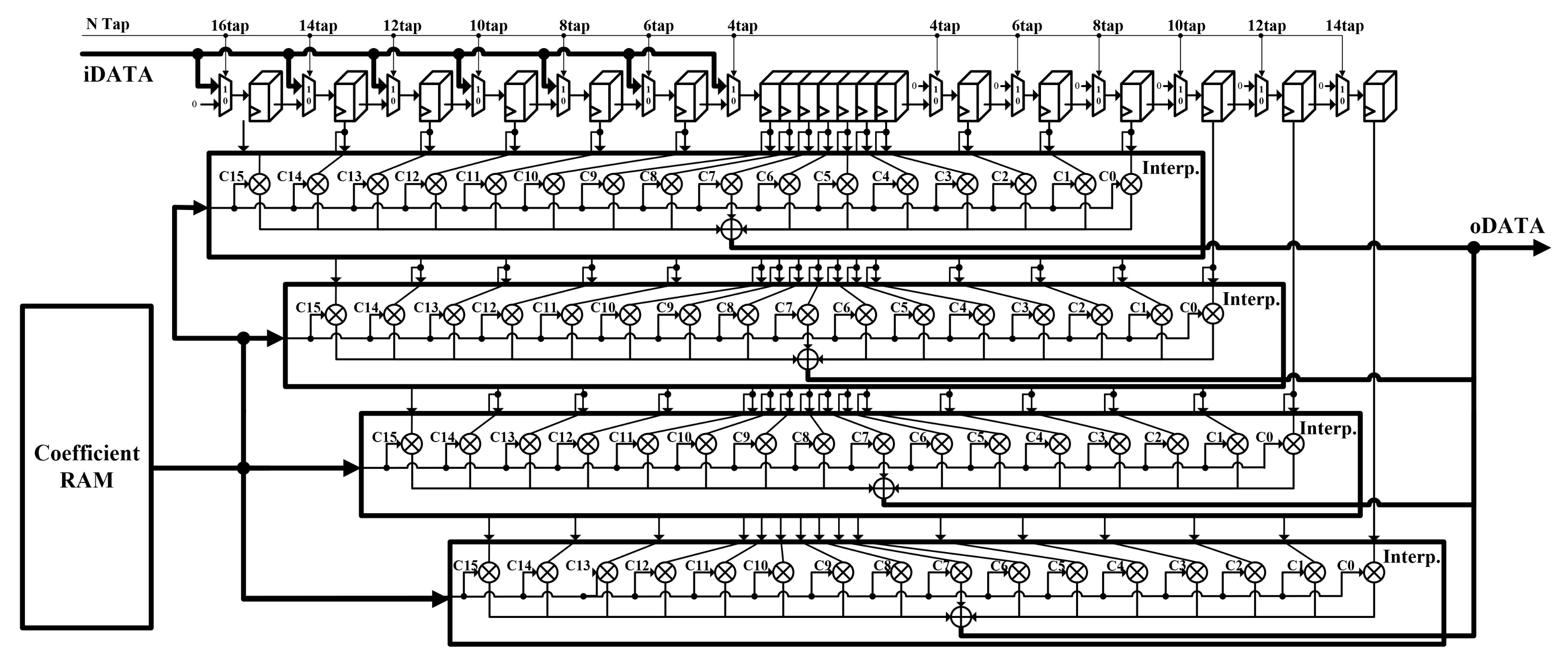
3.2. Range Cell Migration Correction Processing Unit (RPU)

The proposed RPU consisted of registers, coefficient RAM, and interpolation modules, as shown in Figure 4. Each register stored 32 bits of data, which were shifted to the next register at every clock cycle. The coefficient RAM was wired to the slave interface, which was designed to allow the microprocessor to store various kernel coefficients. The interpolation modules performed a dot product with the kernel coefficients by using the input data stored in the registers. The RPU was designed to have four interpolation modules to facilitate parallel computation of the data at each clock cycle. In addition, the desired tap could be set through the slave interface, and multiplexers were located between registers to allow the tap size of interpolation to be changed to 4/6/8/10/12/14/16 taps.

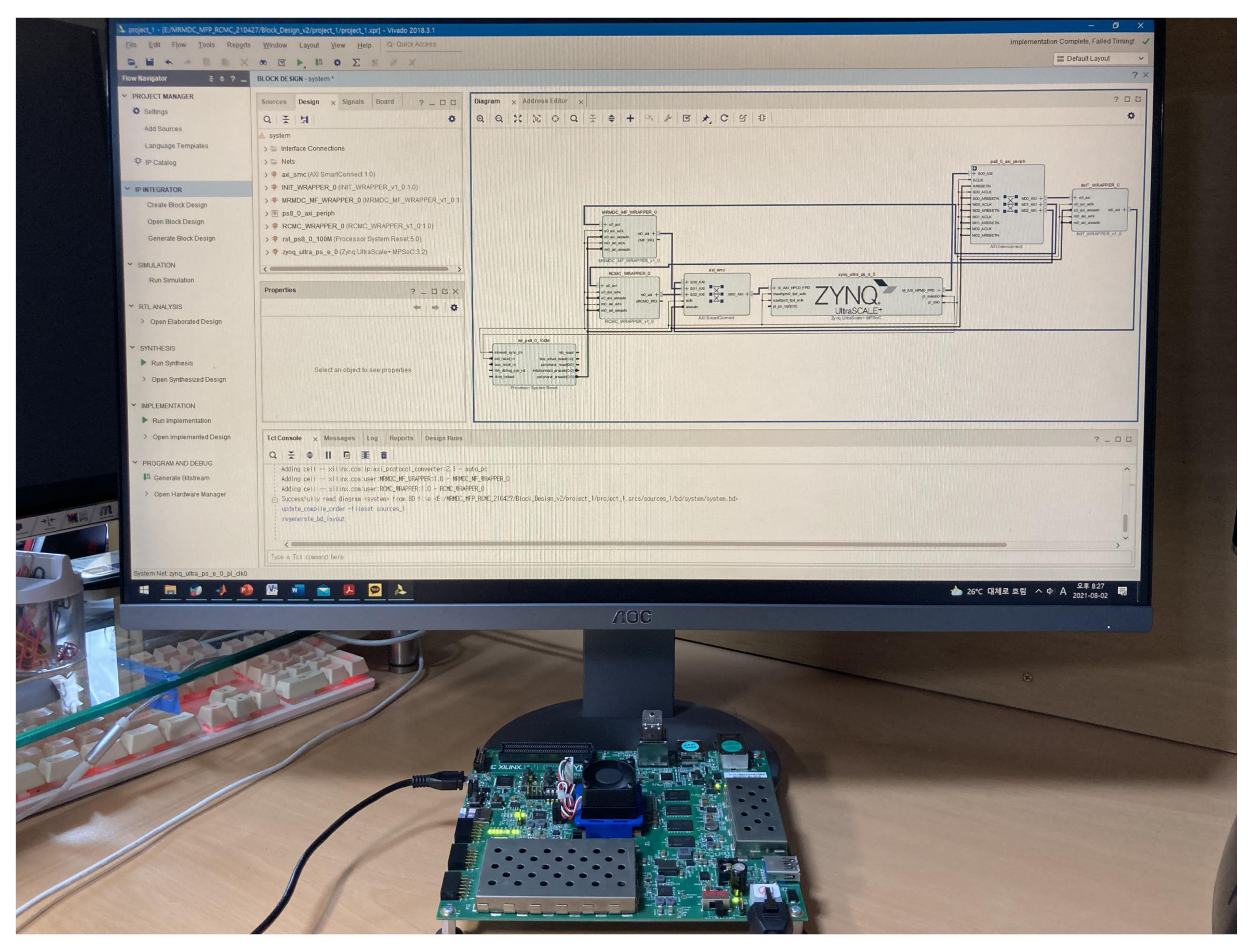
4. Implementation and Acceleration Results

The MFU and RPU included in the proposed RDA-based SAR processor were designed using the Verilog hardware description language (HDL) and were implemented on a Xilinx Zynq Ultrascale+ FPGA device. Thus, the MFU was implemented with 8836 CLBs, 48,077 CLB LUTs, eight block RAMs, and 112 DSPs, whereas the RPU was implemented with 914 CLBs, 3465 CLB LUTs, four block RAMs, and 256 DSPs, as listed in Table 1. The MFU and RPU could process at maximum operating frequencies of 314 and 312 MHz, respectively. The power consumption of the proposed RDA-based SAR processor was measured to be 1.31 W. Figure 5 shows the verification environment used for the FPGA platform.
The raw data used for verifying our RDA-based SAR processor were loaded into the DDR memory. Subsequently, when the start signal of the MFU was entered through the microprocessor, the raw data in the DDR memory were transferred to the cache RAM of the MFU through the master interface. The MFU then performed range compression. Next, the results of the MFU were output to the DDR memory through the master interface. In addition, to perform the azimuth FFT, the MFU was set to the FFT mode using the microprocessor. Subsequently, when the start signal of the FFT-mode MFU was entered through the microprocessor, the range-compressed data in the DDR memory were transferred to the cache RAM of the FFT-mode MFU. After completing the FFT operation, the data stored in the cache RAM of the FFT-mode MFU were transferred back to the DDR memory. RCMC and azimuth compression were performed similarly.
Figure 6 presents the point-target-based verification results for the RDA’s intermediate step. The measured SAR image quality parameters for the peak-to-sidelobe ratio (PSLR) were −13.04 dB (range) and −13.37 dB (azimuth). Regarding the integrated sidelobe ratio (ISLR), the values of −10.24 dB (range) and −10.54 dB (azimuth) were measured. In addition, we used a RADARSAT-1 dataset that was collected on 16 June 2002 to verify the proposed hardware using actual SAR data. More specifically, we used an image of Vancouver, Canada from RADARSAT-1’s Fine Beam 2 [35]. The results of ARM Cortex-A53-based software processing were used as a reference to evaluate the resulting image quality of the proposed hardware. The peak signal-to-noise ratio (PSNR) of the actual SAR data processed by the proposed hardware was 55.8 dB. Wei Di et al. achieved a PSNR of 41.8 dB [43]. Yohei Sugimoto et al. measured a PSNR of 45.2 dB [44]. By comparing the PSNR quality parameter, it was verified that the proposed RDA-based SAR processor presented better performance than those of [43,44]. Figure 7 illustrates the SAR image obtained after processing the actual SAR data.
Table 2 presents the evaluation results in terms of RDA execution time. To evaluate the speed performance of the designed MFU and RPU, we measured the execution times of the different sub-operations of the RDA in the ARM Cortex-A53-based software implementation. The RCMC operation was accelerated by the RPU, and the matched filtering and FFT operations were accelerated by the MFU. We calculated the acceleration in the execution times for the RCMC, matched filtering, and FFT operations. The experimental results indicate that the calculation time decreased from approximately 70.33 s to approximately 0.823 s for a 2048 × 2048 pixel image, resulting in an 85-fold acceleration. Considering the sampling rate of 60 MHz for the raw data of the size of 2048 × 2048, the time taken to load the data into the DDR memory was expected to be around 0.069 s. Since the execution time of the proposed SAR processor was 0.823 s, the total processing time was 0.892 s, and the SAR images were expected to be generated at the rate of 1.1 Hz. If the proposed SAR processor is implemented with a high-end FPGA or very-large-scale integrated circuit (VLSI), it is expected that the imaging speed will be further improved.
Table 3 presents the results of the comparison in terms of the normalized execution time for the proposed RDA-based SAR processor and the RDA-based SAR processors presented in References [17,18,19]. Making an accurate comparison between the proposed RDA-based SAR processor and those from related works is problematic because they were implemented in different FPGA devices. However, to make the fairest comparison possible, we compared the speed performance in terms of the normalized execution time, which was calculated based on the FPGA process technology and image size. The normalized execution time used for comparison can be expressed as
T n o r m = ( 16 nm / T e c h n o l o g y ) I m a g e S i z e × E x e c u t i o n T i m e
where “Technology” denotes the CMOS process technology expressed in nanometers. As this value increases, the operation speed decreases, thereby increasing the execution time. With an increase in image size, which is the size of the input data, the execution time increases. According to the results of the comparison, the proposed RDA-based SAR processor offers the fastest execution time compared with those from the related studies.

5. Conclusions

In this study, we proposed a design for an RDA-based SAR processor architecture consisting of an MFU and an RPU. The FFT module included in the MFU was designed to support a variable FFT length and reduce the number of non-trivial multipliers by employing a mixed-radix algorithm. The FFT module used an MDC pipeline architecture to enable the high-throughput processing of four 32-bit data per clock cycle. In addition, the MFU reduced the memory requirements due to the DIT FFT and DIF IFFT modules. The RCMC processor provided a variable tap size and variable interpolation kernel and was able to process the four 32-bit data in parallel. The proposed processor was implemented with 9750 CLBs, 51542 CLB LUTs, 12 block RAMs, and 368 DSPs on a Xilinx Zynq Ultrascale+ FPGA device. For an image with 2048 × 2048 pixels, we achieved an approximately 85-fold acceleration compared with the available software. We computed the normalized execution time and compared the results with those from related studies. The proposed RDA-based SAR processor exhibited the fastest normalized execution time compared with the RDA-based SAR processors from previous studies, despite supporting the RCMC operation.
Future work will involve a focus on other SAR imaging algorithms, such as BPA or PFA. We will then conduct research on the design and implementation of the hardware architecture for such algorithms. Finally, we will attempt to develop an integrated processor that can compute the RDA, BPA, and PFA to flexibly exploit the advantages of each algorithm.

Author Contributions

Y.C. designed the MFU and RCU, performed the simulation and experiment, and wrote the paper. D.J., M.L., and W.L. implemented the processor and performed the revision of this manuscript. Y.J. conceived of and led the research, analyzed the experimental results, and wrote the paper. All authors read and agreed to the published version of the manuscript.

Funding

This research had no funding.

Acknowledgments

The authors gratefully acknowledge the support from the Next-Generation SAR Research Laboratory at Korea Aerospace University, originally funded by the Defense Acquisition Program Administration (DAPA) and Agency for Defense Development (ADD).

Conflicts of Interest

The authors declare no conflict of interest.

References

  1. Chan, Y.K.; Koo, V.C. An introduction to synthetic aperture radar (SAR). Prog. Electromagn. Res. B 2008, 3, 27–60. [Google Scholar] [CrossRef] [Green Version]
  2. Soumekh, M. Synthetic Aperture Radar Signal Processing with MATLAB Algorithms; Wiley Interscience: New York, NY, USA, 1999. [Google Scholar]
  3. Quegan, S. Spotlight synthetic aperture radar: Signal processing algorithms. J. Atmos. Sol.-Terr. Phys 1997, 59, 597–598. [Google Scholar] [CrossRef]
  4. Curlander, J.C.; McDonough, R.N. Synthetic Aperture Radar: Systems and Signal Processing; Wiley: New York, NY, USA, 1991. [Google Scholar]
  5. Kim, S.M.; Jeon, S.Y.; Kim, J.B.; Lee, U.M.; Shin, S.H.; Choi, Y.W.; Ka, M.H. Multichannel W-Band SAR System on a Multirotor UAV Platform With Real-Time Data Transmission Capabilities. IEEE Access 2020, 8, 144413–144431. [Google Scholar] [CrossRef]
  6. Deguchi, T.; Sugiyama, T.; Kishimoto, M. R&D of drone-borne SAR system. Int. Arch. Photogramm. Remote Sens. Spat. Inf. Sci. 2019, XLII-2/W13, 263–267. [Google Scholar]
  7. Zhu, C.; Guan, Y. Study of ground moving target parameters estimation and imaging for Mini-SAR. In Proceedings of the International Conference on Image, Vision and Computing (ICIVC), Chengdu, China, 2–4 June 2017; pp. 587–591. [Google Scholar]
  8. Edwards, M.; Madsen, D.; Stringham, C.; Margulis, A.; Wicks, B.; Long, D.G. MicroASAR: A small, robust LFM-CW SAR for operation on UAVS and small aircraft. In Proceedings of the International Geoscience and Remote Sensing Symposium (IGARSS), Boston, MA, USA, 7–11 July 2008; Volume 5, pp. 514–517. [Google Scholar]
  9. Essen, H.; Stanko, S.; Sommer, R.; Johannes, W.; Wahlen, A.; Wilcke, J.; Hantscher, S. Millimetre Wave SAR for UAV Operation. In Proceedings of the 2011 Asia-Pacific Microwave Conference, Melbourne, Australia, 5–8 December 2011. [Google Scholar]
  10. Zaugg, E.C.; Hudson, D.L.; Long, D.G. The BYU μSAR: A Small, Student–Built SAR for UAV Operation. In Proceedings of the 2006 IEEE International Symposium on Geoscience and Remote Sensing, Denver, CO, USA, 31 July–4 August 2006. [Google Scholar]
  11. Hang, L.; Sheng, J.; Xing, M.; Qiao, Z.; Xiong, T.; Bao, Z. Wavenumber-Domain Autofocusing for Highly Squint UAV SAR imagery. IEEE Sens. J. 2012, 12, 1574–1588. [Google Scholar]
  12. Britton, A.; Joynson, D. An all weather millimetre wave imaging radar for UAVs. Aeronaut. J. 2001, 105, 609–612. [Google Scholar] [CrossRef]
  13. Gebrehiwot, A.A.; Hashemi-Beni, L. Three-Dimensional Inundation Mapping Using UAV Image Segmentation and Digital Surface Model. ISPRS Int. J. Geo-Inform. 2021, 10, 144. [Google Scholar] [CrossRef]
  14. Bimber, O.; Kurmi, I.; Schedl, D.C. Synthetic Aperture Imaging With Drones. IEEE Comput. Graph. Appl. 2019, 39, 8–15. [Google Scholar] [CrossRef] [PubMed]
  15. Kim, J.W.; Keon, S.K.; Ok, J.W.; You, E.N.; Kim, D.J.; Sim, Y.W.; Lee, D.H. Real-Time Image Reconstruction for Compact Drone-Borne SAR using GPU Signal Processing. J. Korean Inst. Electromagn. Eng. Sci. 2019, 30, 780–783. [Google Scholar] [CrossRef]
  16. Shao, Y.F.; Wang, R.; Deng, Y.K.; Liu, Y.; Chen, R.; Liu, G.; Loffeld, O. Fast Backprojection Algorithm for Bistatic SAR Imaging. IEEE Geosci. Remote Sens. Lett. 2013, 10, 1080–1084. [Google Scholar] [CrossRef]
  17. Araujo, G.F.; d’Amore, R.; Fernandes, D. Cost-sensitive FPGA implementation of SAR range-doppler algorithm. IEEE Aerosp. Electron. Syst. Mag. 2018, 33, 54–68. [Google Scholar] [CrossRef]
  18. Hou, N.; Zhang, D.; Du, G.; Song, Y. An FPGA-based multi-core system for synthetic aperture radar data processing. In Proceedings of the International Conference on Anti-Counterfeiting, Security and Identification (ASID), Macao, China, 12–14 December 2014. [Google Scholar]
  19. Hossain, M.A.; Elshafiey, I.; Alkanhal, M.A.; Mabrouk, A. Real-time implementation of UWB-OFDM synthetic aperture radar imaging. In Proceedings of the IEEE International Conference on Signal and Image Processing Applications (ICSIPA), Kuala Lumpur, Malaysia, 16–18 November 2011. [Google Scholar]
  20. Duarte, R.P.; Cruz, H. Reconfigurable Accelerator for On-Board SAR Imaging Using the Backprojection Algorithm. In International Symposium on Applied Reconfigurable Computing; Springer: Berlin/Heidelberg, Germany, 2020; pp. 392–401. [Google Scholar]
  21. Crasto, N.; Kumar, T.K.; Anuradha, D.; Barua, P.; Nemani, S. FPGA implementation of back projection algorithm for radar imaging. In Proceedings of the International Conference on Radar, Ottawa, ON, Canada, 29 April–3 May 2013; pp. 97–100. [Google Scholar]
  22. Hettiarachchi, D.L.N.; Balster, E. Fixed Point Processing of the SAR Back Projection Algorithm on FPGA. TechRxiv 2021. Preprint. [Google Scholar]
  23. Wang, D.; Zhu, D.; Liu, R. Video SAR High-speed Processing Technology Based on FPGA. In Proceedings of the IEEE MTT-S International Microwave Biomedical Conference (IMBioC), Nanjing, China, 6–8 May 2019; Volume 1, pp. 1–4. [Google Scholar]
  24. Li, W.; Xu, Z.; Zhu, D. The FPGA implementation of real-time spotlight SAR imaging. In Proceedings of the IGARSS 2018—2018 IEEE International Geoscience and Remote Sensing Symposium, Valencia, Spain, 22–27 July 2018; pp. 6703–6706. [Google Scholar]
  25. Zhu, D.; Zhang, J.; Mao, X.; Zhang, Y.; Wang, X.; Li, Y.; Ding, Y.; Guo, J.; Shi, J. A miniaturized high resolution SAR processor using FPGA. In Proceedings of the EUSAR 2016: 11th European Conference on Synthetic Aperture Radar, Hamburg, Germany, 6–9 June 2016; pp. 1–4. [Google Scholar]
  26. Linchen, Z.; Jindong, Z.; Daiyin, Z. FPGA implementation of polar format algorithm for airborne spotlight SAR processing. In Proceedings of the IEEE International Conference on Dependable Autonomic and Secure Computing, Chengdu, China, 21–22 December 2013; Volume 33, pp. 143–147. [Google Scholar]
  27. Yang, C.; Li, B.; Chen, L.; Wei, C.; Xie, Y.; Chen, H.; Yu, W. A Spaceborne Synthetic Aperture Radar Partial Fixed–Point Imaging System Using a Field–Programmable Gate Array–Application-Specific Integrated Circuit Hybrid Heterogeneous Parallel Acceleration Technique. Sensors 2017, 17, 1493. [Google Scholar] [CrossRef] [PubMed]
  28. Li, Y.; Chen, H.; Xie, Y. An FPGA-Based Four-Channel 128k-Point FFT Processor Suitable for Spaceborne SAR. Electronics 2021, 10, 816. [Google Scholar]
  29. Woo, J.C.; Lim, B.G.; Kim, Y.S. Modification of the Recursive Sidelobe Minimization Technique for the Range-Doppler Algorithm of SAR Imaging. J. Electromagn. Waves Appl. 2011, 25, 1783–1794. [Google Scholar] [CrossRef]
  30. Clemente, C.; Soraghan, J.J. Range Doppler SAR processing using the fractional Fourier transform. In Proceedings of the 11th International Radar Symposium, Vilnius, Lithuania, 16–18 June 2010. [Google Scholar]
  31. Le, C.; Chan, S.; Cheng, F.; Fang, W.; Fischman, M.; Hensley, S.; Johnson, R.; Jourdan, M.; Marina, M.; Parham, B.; et al. Onboard FPGA-based SAR processing for future spaceborne systems. In Proceedings of the IEEE 2004 Radar Conference, Philadelphia, PA, USA, 29–29 April 2004; pp. 15–20. [Google Scholar]
  32. Wang, D.; Ali, M.; Blinka, E. Synthetic Aperture Radar (SAR) Implementation on a TMS320C6678 Multicore DSP; Texas Instruments: Dallas, TX, USA, 2015. [Google Scholar]
  33. Raei, E.; Modarres-Hashemi, M.; Shankar, M.B. Range Cell Migration Correction by Fractional Fourier Transform in Synthetic Aperture Radars. In Proceedings of the 20th International Radar Symposium (IRS), Ulm, Germany, 26–28 June 2019; pp. 1–10. [Google Scholar]
  34. Hao, R.; Guo, T. Signal Processing Based Remote Sensing Data Simulation in Radar System. J. Electr. Comput. Eng. 2017, 2017, 6780305. [Google Scholar] [CrossRef] [Green Version]
  35. Cumming, I.; Wong, F. Digital Processing of Synthetic Aperture Radar Data; Artech House: Boston, MA, USA, 2005. [Google Scholar]
  36. Langemeyer, S.; Pirsch, P.; Blume, H. A FPGA architecture for real-time processing of variable-length FFTs. In Proceedings of the IEEE International Conference on Acoustics, Speech and Signal Processing (ICASSP), Prague, Czech Republic, 22–27 May 2011. [Google Scholar]
  37. Qureshi, F.; Takala, J.; Volkova, A.; Hilaire, T. Multiplierless unified architecture for mixed radix-2/3/4 FFTs. In Proceedings of the 2017 25th European Signal Processing Conference (EUSIPCO), Kos Island, Greece, August 28–2 September 2017; Volume 25, pp. 1334–1338. [Google Scholar]
  38. Jung, Y.C.; Cho, J.C.; Jung, Y.H. Design and Implementation of Multi-channel FFT Processor for MIMO Systems. J. Adv. Navig. Technol. 2017, 21, 659–665. [Google Scholar]
  39. Jang, S.H.; Yang, G.J.; Lee, S.J.; Jung, Y.H. Area-efficient FFT processor for MIMO-OFDM based SDR systems. IEICE Electron. Express 2013, 10, 20130490. [Google Scholar] [CrossRef] [Green Version]
  40. Lee, S.; Park, S. Modified SDF Architecture for Mixed DIF/DIT FFT. In Proceedings of the 2007 IEEE International Symposium on Circuits and Systems (ISCAS), New Orleans, LA, USA, 27–30 May 2007; pp. 2590–2593. [Google Scholar]
  41. Jeon, H.H.; Jung, Y.C.; Lee, S.J.; Jung, Y.H. Area-Efficient Short-Time Fourier Transform Processor for Time–Frequency Analysis of Non-Stationary Signals. Appl. Sci. 2020, 10, 7208. [Google Scholar] [CrossRef]
  42. Jang, J.K.; Sunwoo, M.H. Efficient Scheduling Schemes for Low-Area Mixed-radix MDC FFT Processor. J. Inst. Electron. Inf. Eng. 2017, 54, 29–35. [Google Scholar]
  43. Di, W.; Chen, C.; Liu, Y. FPGA-based parallel system for synthetic aperture radar imaging. In Proceedings of the 2018 International Conference on Electronics Technology (ICET), Chengdu China, 23–27 May 2018; pp. 430–433. [Google Scholar]
  44. Sugimoto, Y.; Ozawa, S.; Inaba, N. Near Real-Time Sar Image Focusing Onboard Spacecraft. In Proceedings of the IGARSS 2018—2018 IEEE International Geoscience and Remote Sensing Symposium, Valencia, Spain, 22–27 July 2018; pp. 8038–8041. [Google Scholar]
Figure 1. Procedure of the range-Doppler algorithm.
Electronics 10 02133 g001
Figure 2. Block diagram of the proposed RDA-based SAR processor.
Electronics 10 02133 g002
Figure 3. Block diagram of the proposed matched filtering unit.
Electronics 10 02133 g003
Figure 4. Block diagram of the proposed range cell migration correction processing unit.
Electronics 10 02133 g004
Figure 5. Verification environment for the proposed FPGA implementation.
Electronics 10 02133 g005
Figure 6. Point target simulation results: (a) raw data; (b) range FFT results; (c) range compression results; (d) azimuth FFT results; (e) RCMC results; (f) azimuth compression results (point target results).
Electronics 10 02133 g006
Figure 7. Actual SAR images derived using the (a) ARM Cortex-A53-based software and (b) the proposed FPGA-based hardware.
Electronics 10 02133 g007
Table 1. Implementation results based on the Xilinx Zynq Ultrascale+ FPGA device.
UnitCLBCLB LUTBlock RAMsDSPMax. Operating Clock Freq.
MFU883648,0778112314 MHz
RPU91434654256312 MHz
Table 2. RDA execution time.
Image SizeExecution Time (s)
Full SWRCMC Accel.MF/FFT Accel.Full Accel.
256 × 2560.8050.6910.1220.007
512 × 5123.6483.1140.5740.030
1024 × 102416.11413.8502.4200.188
2048 × 204870.33061.2769.9510.823
Table 3. Comparison with previous implementations.
WorkPlatformImage SizeHardware ResourcesRCMCOperating Freq. (MHz)Exec. Time (s)Tech. (nm) T norm ( μ s)
ProposedZynq UlatraScale+2048 × 2048CLB: 9750
CLB LUT: 51,542
Block RAMs: 12
DSP: 368
O3000.823160.2
[17]Intel Altera Cyclone E IV2048 × 2048Logic Elements: 65,209
Logic Registers: 35,069
Memory (kbit): 814
Embedded Multipliers: 297
O50020.31601.3
[18]Xilinx Virtex-62048 × 4096N/AX13012.03400.57
[19]Xilinx Virtex-6900 × 2048N/AO2002.08400.45
Publisher’s Note: MDPI stays neutral with regard to jurisdictional claims in published maps and institutional affiliations.

