
Real-Time Identification of Knee Joint Walking Gait as Preliminary Signal for Developing Lower Limb Exoskeleton

 , ,
, , 
Abstract
:1. Introduction
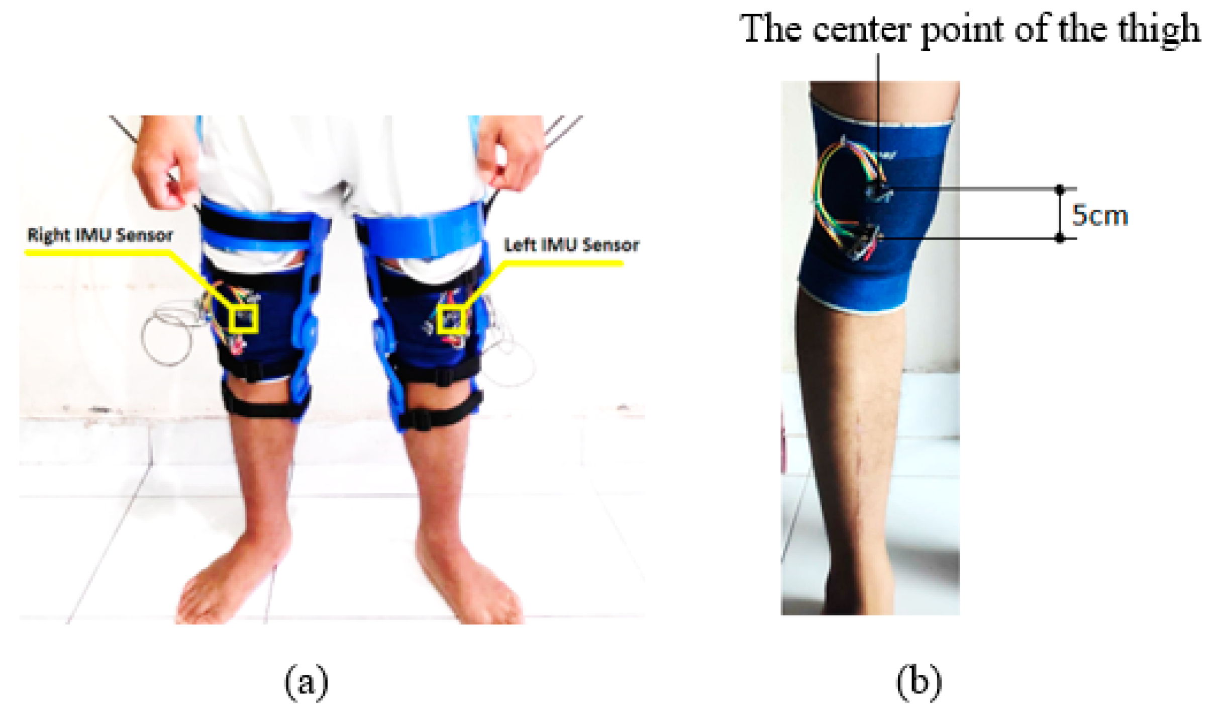
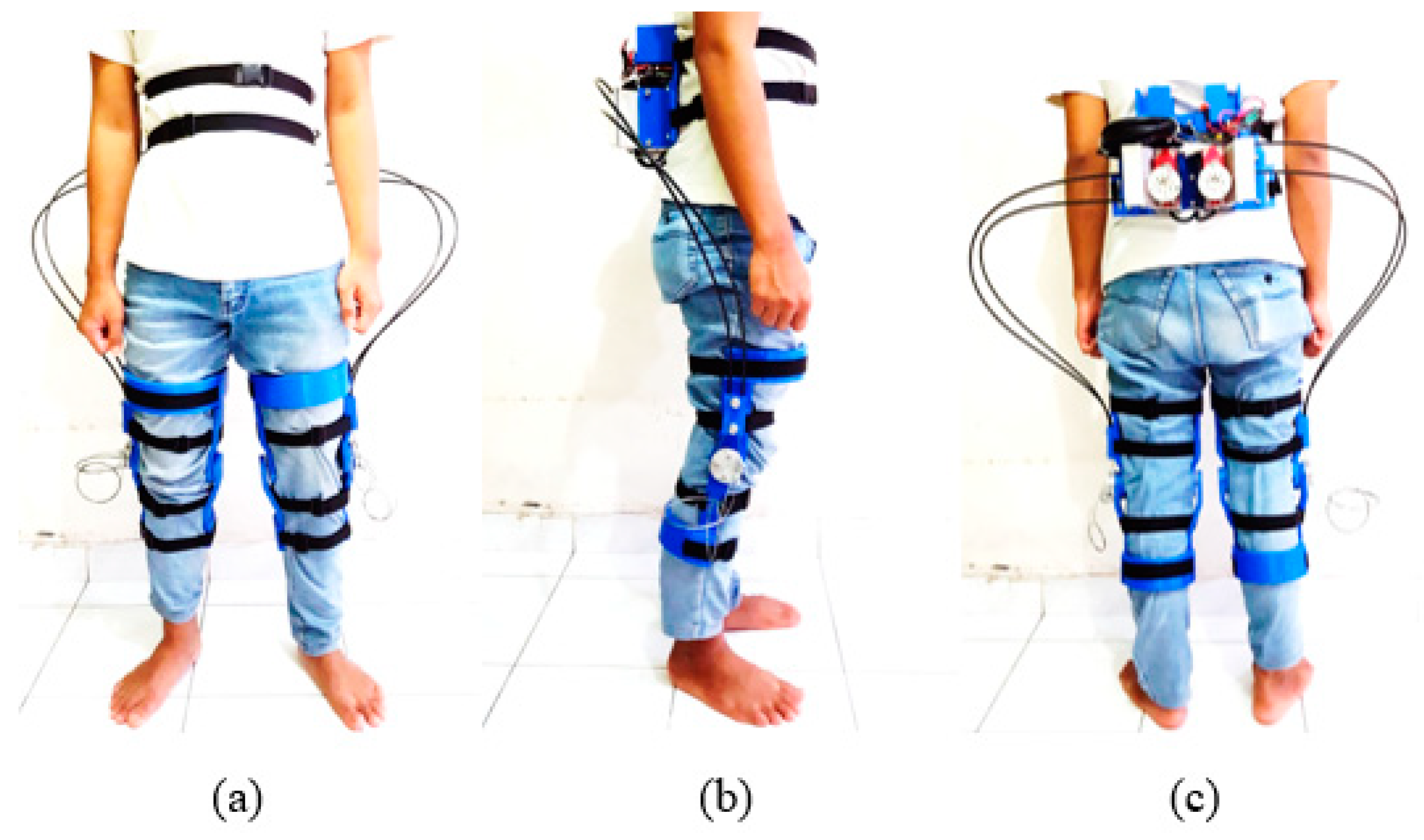
2. Sensor Placement
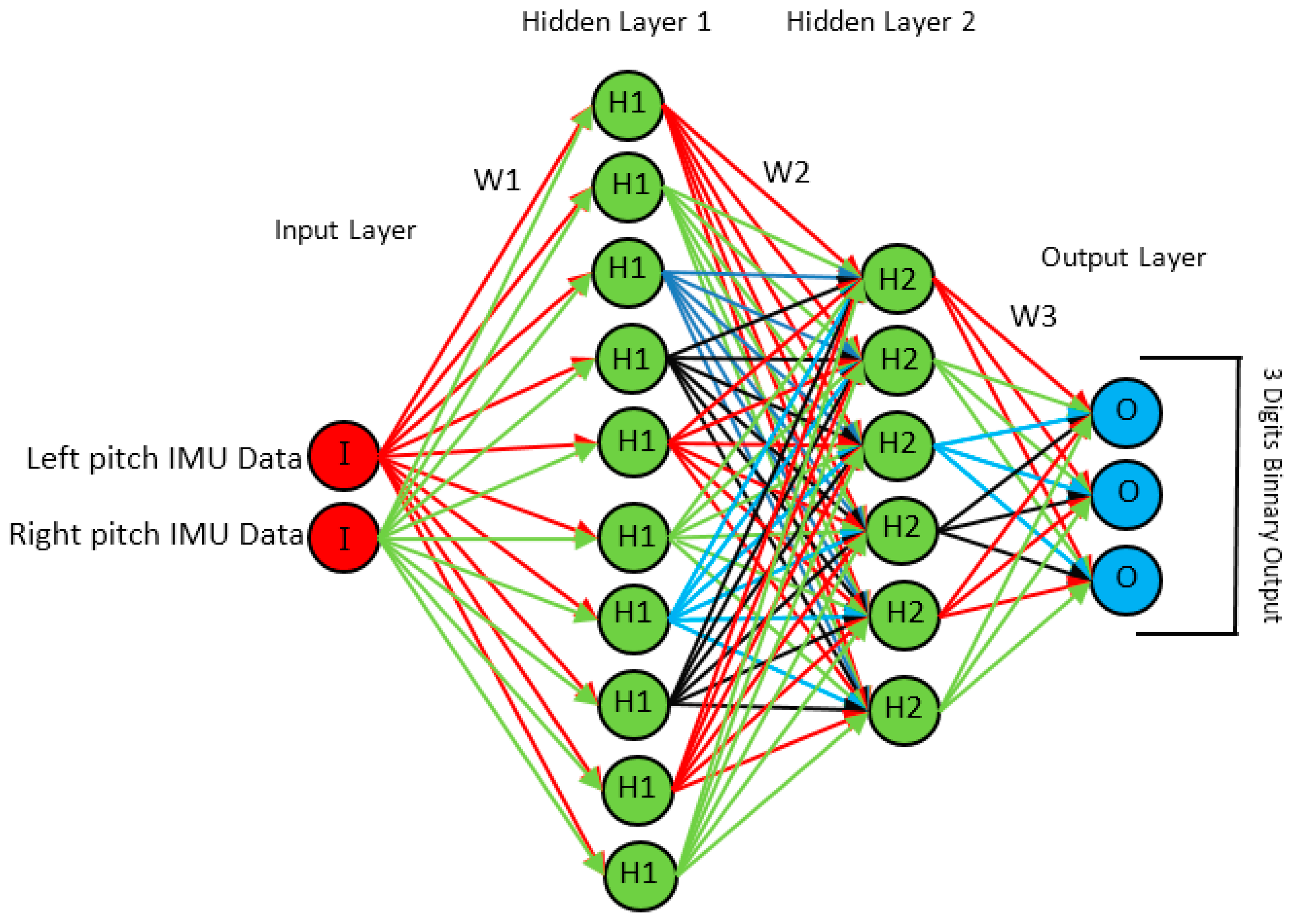
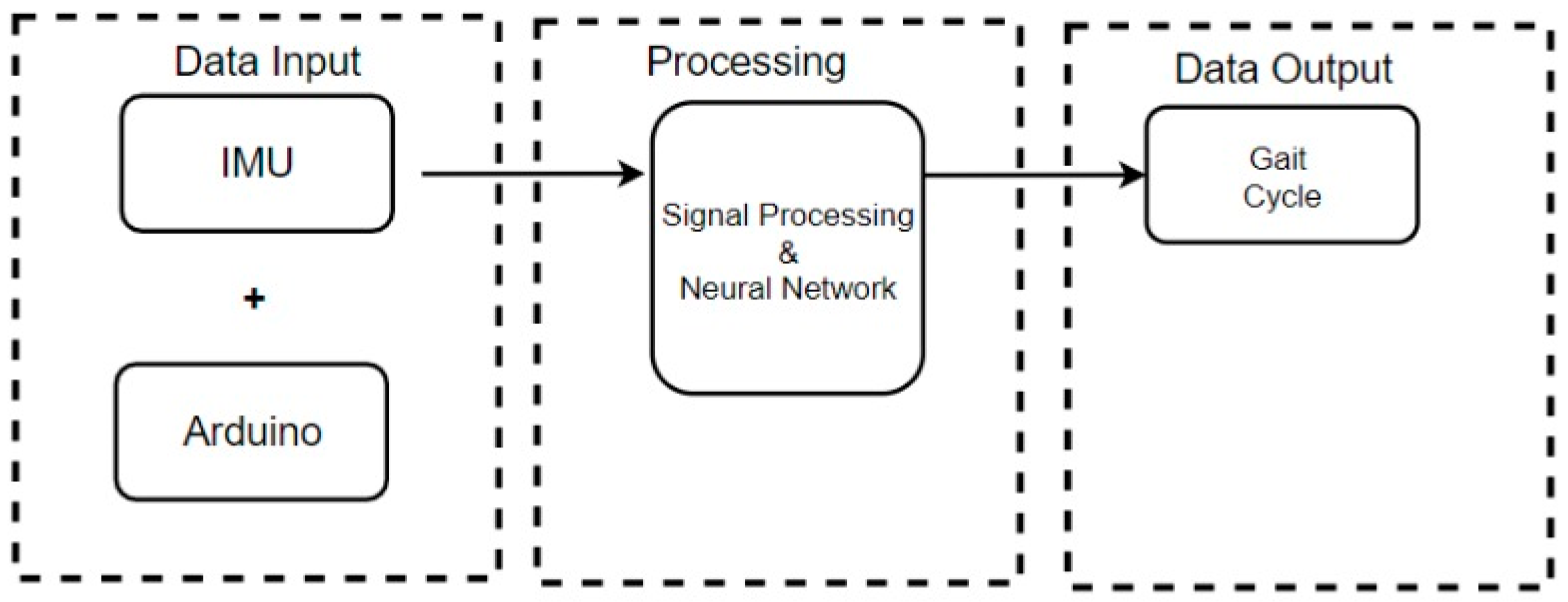
3. Methods
- O = Output
- I = Input
- H(1) = Activation function in layer 1
- H(2) = Activation function in layer 2
- H(3) = Activation function in layer 3
- W(1) = Weight matric for layer 1
- W(2) = Weight matric for layer 2
- W(3) = Weight matric for layer 3
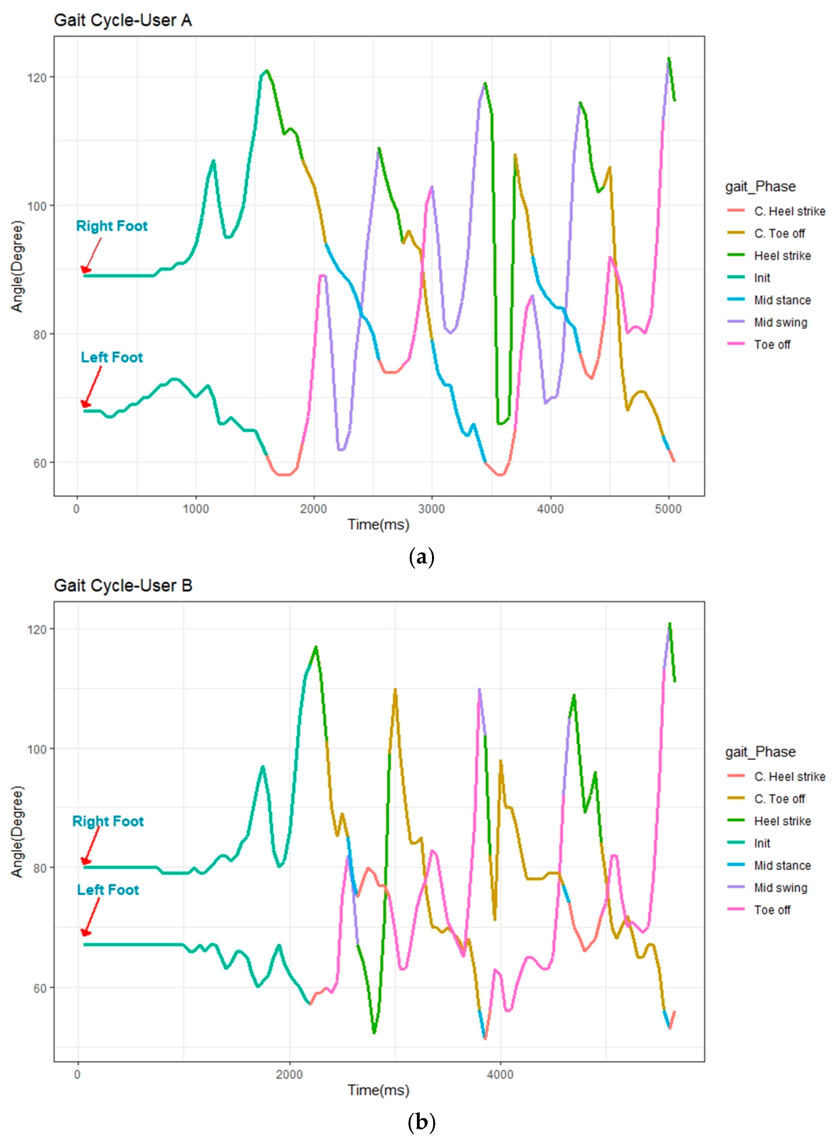
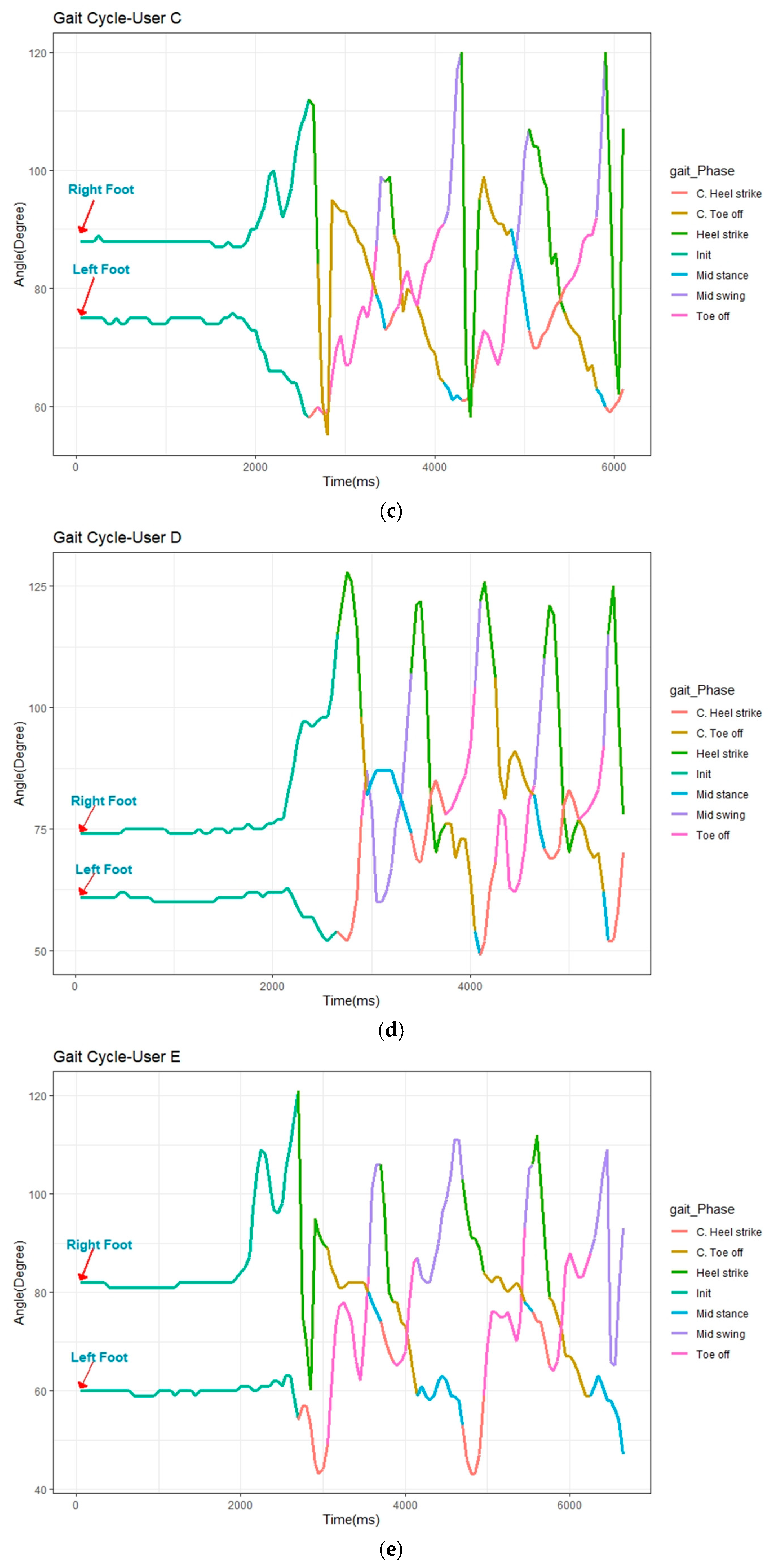
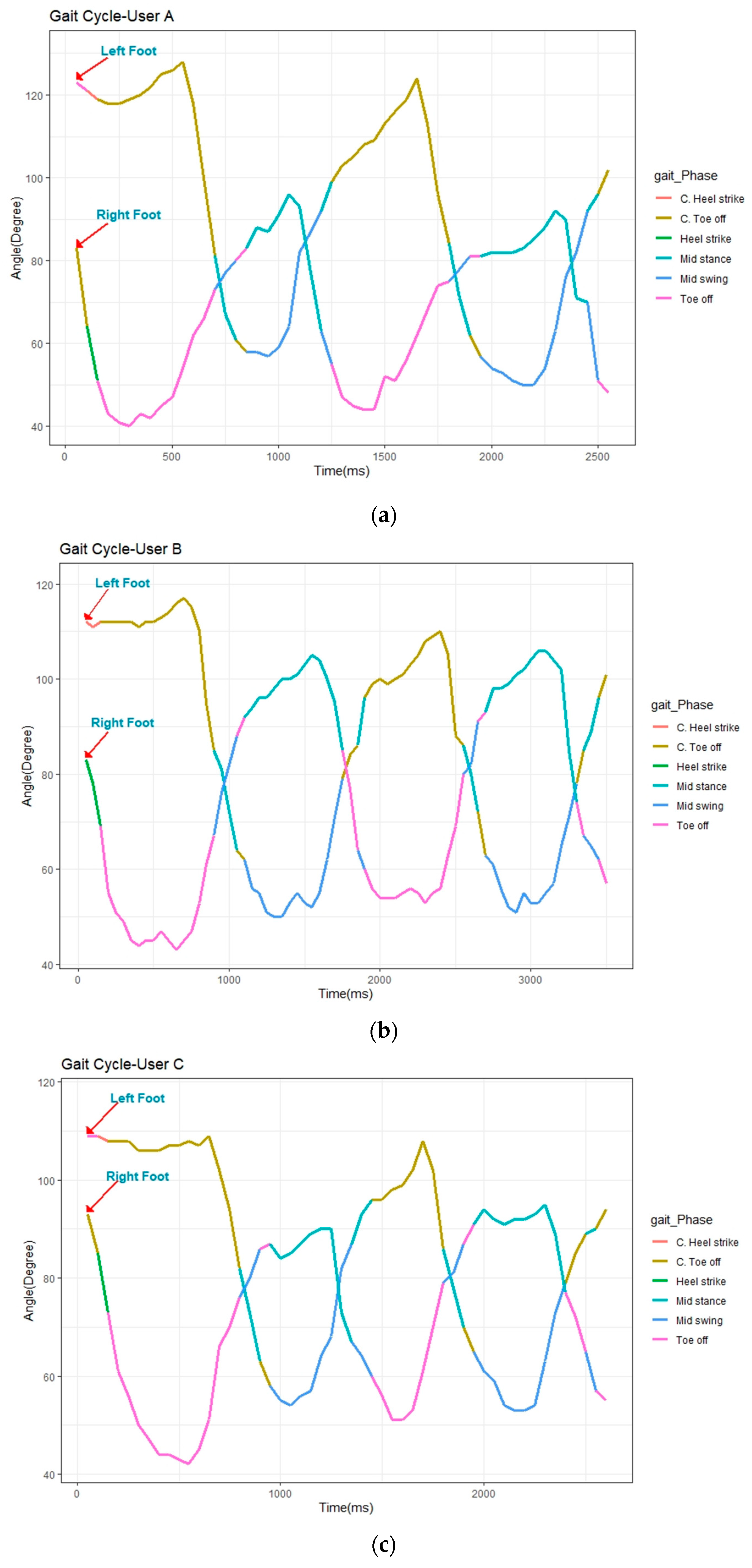
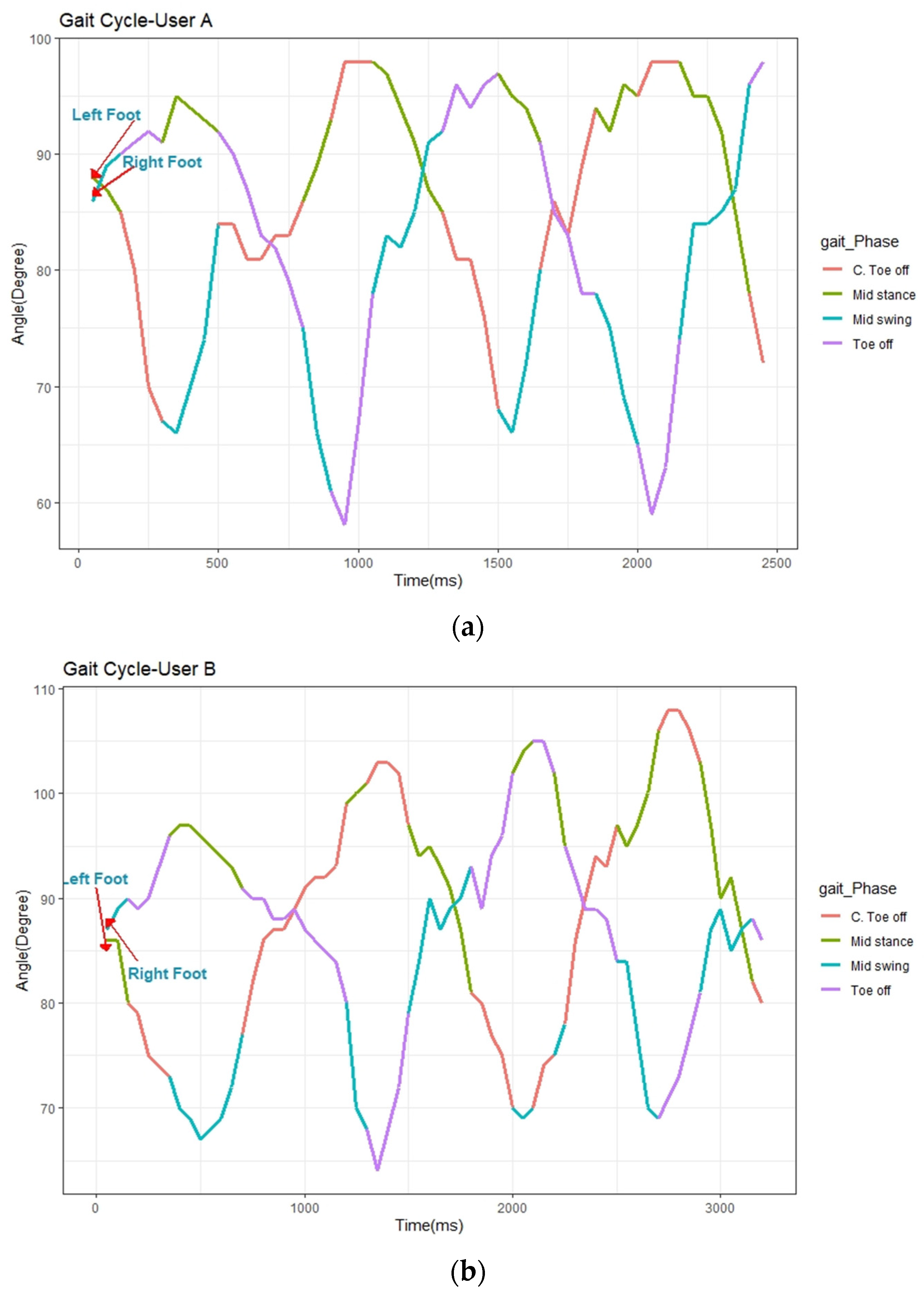
4. Results
5. Conclusions
Author Contributions
Funding
Data Availability Statement
Conflicts of Interest
References
- Gull, M.A.; Bai, S.; Bak, T. A Review on Design of Upper Limb Exoskeletons. Robotics 2020, 9, 16. [Google Scholar] [CrossRef] [Green Version]
- Pamungkas, D.S.; Caesarendra, W.; Soebakti, H.; Analia, R.; Susanto, S. Overview: Types of Lower Limb Exoskeletons. Electronics 2019, 8, 1283. [Google Scholar] [CrossRef] [Green Version]
- Zhou, J.; Yang, S.; Xue, Q. Lower limb rehabilitation exoskeleton robot: A review. Adv. Mech. Eng. 2021, 13. [Google Scholar] [CrossRef]
- Shi, D.; Zhang, W.; Zhang, W.; Ding, X. A Review on Lower Limb Rehabilitation Exoskeleton Robots. Chin. J. Mech. Eng. 2019, 32, 74. [Google Scholar] [CrossRef] [Green Version]
- Rewalk by ARGO Medical Technologies, Inc. Available online: http://www.rewalk.com (accessed on 19 December 2019).
- Sankai, Y. Leading Edge of Cybernics: Robot Suit HAL. In Proceedings of the 2006 SICE-ICASE International Joint Conference, Busan, Korea, 18–21 October 2006; pp. P-1–P-2. [Google Scholar] [CrossRef]
- Kazerooni, H.; Steger, R.; Huang, L. Hybrid Control of the Berkeley Lower Extremity Exoskeleton (BLEEX). Int. J. Robot. Res. 2006, 25, 561–573. [Google Scholar] [CrossRef]
- Kazerooni, H.; Racine, J.; Huang, L.; Steger, R. On the Control of the Berkeley Lower Extremity Exoskeleton (BLEEX). In Proceedings of the 2005 IEEE International Conference on Robotics and Automation, Barcelona, Spain, 18–22 April 2005; pp. 4353–4360. [Google Scholar] [CrossRef]
- Malcolm, P.; Derave, W.; Galle, S.; de Clercq, D. A Simple Exoskeleton That Assists Plantarflexion Can Reduce the Metabolic Cost of Human Walking. PLoS ONE 2013, 8, e56137. [Google Scholar] [CrossRef] [PubMed] [Green Version]
- Castagneri, C.; Agostini, V.; Balestra, G.; Knaflitz, M.; Carlone, M.; Massazza, G. EMG Asymmetry Index in Cyclic Movements. In Proceedings of the 2018 IEEE Life Sciences Conference (LSC), Montreal, QC, Canada, 28–30 October 2018; pp. 223–226. [Google Scholar] [CrossRef]
- Meng, M.; She, Q.; Gao, Y.; Luo, Z. EMG signals based gait phases recognition using hidden Markov models. In Proceedings of the 2010 IEEE International Conference on Information and Automation, Harbin, China, 20–23 June 2010; pp. 852–856. [Google Scholar] [CrossRef]
- Pawin, J.; Khaorapapong, T.; Chawalit, S. Neural-based human’s abnormal gait detection using Force Sensitive Resistors. In Proceedings of the Fourth International Workshop on Advanced Computational Intelligence, Wuhan, China, 19–21 October 2011; pp. 224–229. [Google Scholar] [CrossRef]
- Chandel, V.; Singhal, S.; Sharma, V.; Ahmed, N.; Ghose, A. PI-Sole: A Low-Cost Solution for Gait Monitoring Using Off-The-Shelf Piezoelectric Sensors and IMU. In Proceedings of the 2019 41st Annual International Conference of the IEEE Engineering in Medicine and Biology Society (EMBC), Berlin, Germany, 23–27 July 2019; pp. 3290–3296. [Google Scholar] [CrossRef]
- Aqueveque, P.; Germany, E.; Osorio, R.; Pastene, F. Gait Segmentation Method Using a Plantar Pressure Measurement System with Custom-Made Capacitive Sensors. Sensors 2020, 20, 656. [Google Scholar] [CrossRef] [PubMed] [Green Version]
- Susanto, R.A.; Song, K. Design of assistive torque for a lower limb exoskeleton based on motion prediction. In Proceedings of the 2016 55th Annual Conference of the Society of Instrument and Control Engineers of Japan (SICE), Tsukuba, Japan, 20–23 September 2016; pp. 172–177. [Google Scholar] [CrossRef]
- Luu, T.P.; Brantley, J.A.; Zhu, F.; Contreras-Vidal, J.L. Electrocortical amplitude modulations of human level-ground, slope, DSP: OK you can delete it and stair walking. In Proceedings of the 2017 39th Annual International Conference of the IEEE Engineering in Medicine and Biology Society (EMBC), Seogwipo, Korea, 11–15 July 2017; pp. 1913–1916. [Google Scholar] [CrossRef]
- Villarreal, D.J.; Poonawala, H.A.; Gregg, R.D. A Robust Parameterization of Human Gait Patterns Across Phase-Shifting Perturbations. IEEE Trans. Neural Syst. Rehabil. Eng. 2017, 25, 265–278. [Google Scholar] [CrossRef] [PubMed] [Green Version]
- Kim, W.; Kim, Y.; Lee, K.Y. Human Gait Recognition Based on Integrated Gait Features using Kinect Depth Cameras. In Proceedings of the 2020 IEEE 44th Annual Computers, Software, and Applications Conference (COMPSAC), Madrid, Spain, 13–17 July 2020; pp. 328–333. [Google Scholar] [CrossRef]
- Wang, L.; Jia, S.; Li, X.; Wang, S. Human gait recognition based on gait flow image considering walking direction. In Proceedings of the 2012 IEEE International Conference on Mechatronics and Automation, Chengdu, China, 5–8 August 2012; pp. 1990–1995. [Google Scholar] [CrossRef]
- Yusuf, S.I.; Adeshina, S.; Boukar, M.M. Parameters for Human Gait Analysis: A Review. In Proceedings of the 2019 15th International Conference on Electronics, Computer and Computation (ICECCO), Abuja, Nigeria, 10–12 December 2019; pp. 1–4. [Google Scholar] [CrossRef]
- Roberts, M.; Mongeon, D.; Prince, F. Biomechanical parameters for gait analysis: A systematic review of healthy human gait. Phys. Ther. Rehabil. 2017, 4, 6. [Google Scholar] [CrossRef]
- Posada-Gomez, R.; Martinez, M.A.G.; Aguila-Rodriguez, G.; Daul, C.; Salas, L.L. Conception and realization of a 3D dynamic sensor as a tool in human walking study. In Proceedings of the 2005 2nd International Conference on Electrical and Electronics Engineering, Mexico City, Mexico, 7–9 September 2005; pp. 178–181. [Google Scholar] [CrossRef]
- Bakchy, S.C.; Islam, M.R.; Sayeed, A. Human identification on the basis of gait analysis using Kohonen self-organizing mapping technique. In Proceedings of the 2016 2nd International Conference on Electrical, Computer & Telecommunication Engineering (ICECTE), Rajshahi, Bangladesh, 8–10 December 2016; pp. 1–4. [Google Scholar] [CrossRef]
- Miranda-Pereira, P.A.; Milián-Ccopa, L.P. Brief biomechanical analysis on the walking for a lower-limb rehabilitation exoskeleton. In Proceedings of the 2016 IEEE International Symposium on Robotics and Intelligent Sensors (IRIS), Tokyo, Japan, 17–20 December 2016; pp. 67–72. [Google Scholar] [CrossRef]
- Yoneyama, M.; Kurihara, Y.; Watanabe, K.; Mitoma, H. Accelerometry-Based Gait Analysis and Its Application to Parkinson’s Disease Assessment— Part 2: A New Measure for Quantifying Walking Behavior. IEEE Trans. Neural Syst. Rehabil. Eng. 2013, 21, 999–1005. [Google Scholar] [CrossRef] [PubMed]
- Hu, J.-S.; Sun, K.-C.; Cheng, C.-Y. A Kinematic Human-Walking Model for the Normal-Gait-Speed Estimation Using Tri-Axial Acceleration Signals at Waist Location. IEEE Trans. Biomed. Eng. 2013, 60, 2271–2279. [Google Scholar] [CrossRef] [PubMed] [Green Version]
- Mota, F.A.O.; Biajo, V.H.M.; Mota, H.O.; Vasconcelos, F.H. A wireless sensor network for the biomechanical analysis of the gait. In Proceedings of the 2017 IEEE International Instrumentation and Measurement Technology Conference (I2MTC), Turin, Italy, 22–25 May 2017; pp. 1–6. [Google Scholar] [CrossRef]
- Abhayasinghe, N.; Murray, I. Human gait phase recognition based on thigh movement computed using IMUs. In Proceedings of the 2014 IEEE Ninth International Conference on Intelligent Sensors, Sensor Networks and Information Processing (ISSNIP), Singapore, 21–24 April 2014; pp. 1–4. [Google Scholar] [CrossRef] [Green Version]
- Jang, J.; Lee, J.; Lim, B.; Shim, Y. Natural gait event-based level walking assistance with a robotic hip exoskeleton. In Proceedings of the 2018 40th Annual International Conference of the IEEE Engineering in Medicine and Biology Society (EMBC), Honolulu, HI, USA, 17–21 July 2018; pp. 1–5. [Google Scholar] [CrossRef]
- Wang, X.; Ristic-Durrant, D.; Spranger, M.; Gräser, A. Gait assessment system based on novel gait variability measures. In Proceedings of the 2017 International Conference on Rehabilitation Robotics (ICORR), London, UK, 17–20 July 2017; pp. 467–472. [Google Scholar] [CrossRef]
- Chen, J.; Huang, Y.; Guo, X.; Zhou, S.; Jia, L. Parameter identification and adaptive compliant control of rehabilitation exoskeleton based on multiple sensors. Measurement 2020, 159, 107765. [Google Scholar] [CrossRef]
- Analia, R.; Sutopo, P.D.; Soebhakti, H.; Sani, A. Walking Classification of Hip Joint Lower Limb Exoskeleton. In Proceedings of the 2019 2nd International Conference on Applied Engineering (ICAE), Batam, Indonesia, 2–3 October 2019; pp. 1–5. [Google Scholar] [CrossRef]
- Barjuei, E.S.; Ardakani, M.M.G.; Caldwell, D.G.; Sanguineti, M.; Ortiz, J. Optimal Selection of Motors and Transmissions in Back-Support Exoskeleton Applications. IEEE Trans. Med. Robot. Bionics 2020, 2, 320–330. [Google Scholar] [CrossRef]


| No | Sensors | Reference | Description |
|---|---|---|---|
| 1 | EMG | [10] | Statistical Gait Analysis Algorithm |
| 2 | EMG | [11] | Hidden Markov Model Algorithm |
| 3 | Force Sensitive Resistor | [12] | Placed on plantar |
| 4 | Kinect depth cameras | [19] | Captured human walking then perform the body part modeling |
| 5 | IMU | [24] | The sensor was placed on waists |
| 6 | IMU | [26] | The sensor was placed on trouser pocket |
| 7 | IMU | [27] | The sensor placed on pelvis |
| 8 | IMU | [28] | The sensor placed on hip joints |
| 9 | IMU | [32] | The sensor placed on chest |
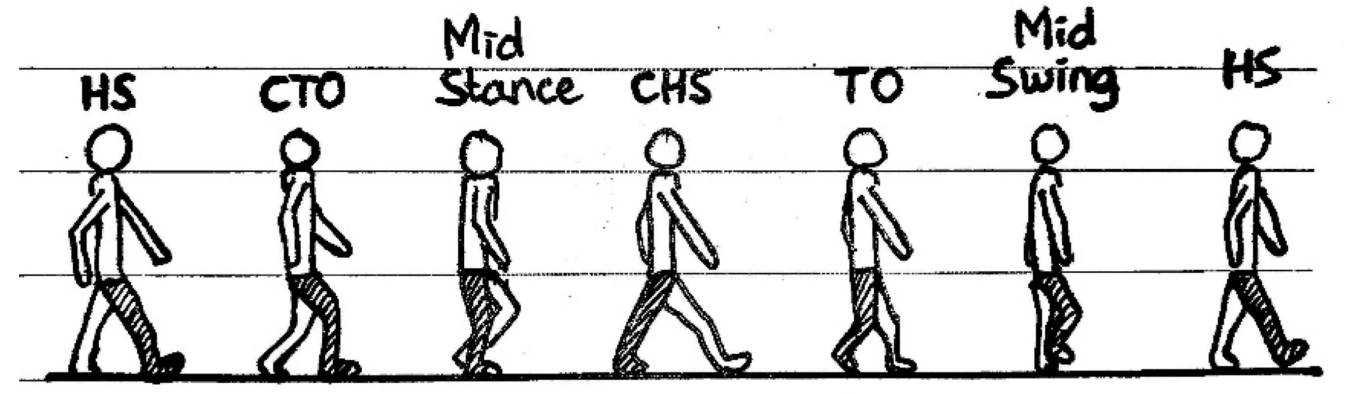
| No | Digits Binary Output | Gait Cycle |
|---|---|---|
| 1 | 000 | Initial |
| 2 | 001 | Heel strike |
| 3 | 010 | Contralateral toe off |
| 4 | 011 | Mid stance |
| 5 | 100 | Contralateral heel strike |
| 6 | 101 | Toe off |
| 7 | 110 | Mid swing |
| No | Walking on Flat Floor | Climbing Up and Down the Stairs | ||||||||
|---|---|---|---|---|---|---|---|---|---|---|
| User | Age (Years) | Height (cm) | *F/M | Weight (Kg) | User | Age (Years) | Height (cm) | *F/M | Weight (Kg) | |
| 1 | User A | 50 | 160 | M | 60 | User A | 17 | 155 | F | 50 |
| 2 | User B | 17 | 155 | F | 50 | User B | 21 | 168 | M | 60 |
| 3 | User C | 21 | 168 | M | 60 | User C | 45 | 150 | F | 65 |
| 4 | User D | 21 | 165 | M | 65 | |||||
| 5 | User E | 45 | 150 | F | 65 | |||||
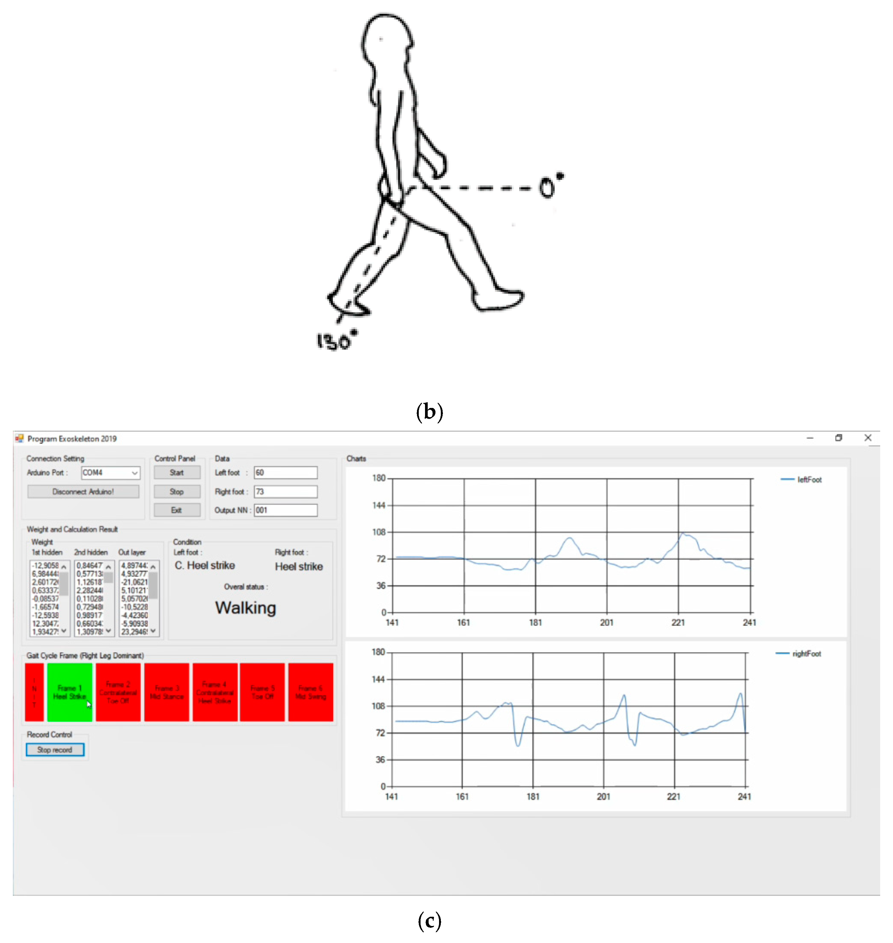
| User | Heel Strike (HS) | Contralateral Toe Off (CTO) | Mid Stance | Contralateral Heel Strike (CHS) | Toe off (TO) | Mid Swing | ||||||
|---|---|---|---|---|---|---|---|---|---|---|---|---|
| Pitch Left (°) | Pitch Right (°) | Pitch Left (°) | Pitch Right (°) | Pitch Left (°) | Pitch Right (°) | Pitch Left (°) | Pitch Right (°) | Pitch Left (°) | Pitch Right (°) | Pitch Left (°) | Pitch Right (°) | |
| User A | 58 | 121 | 63 | 108 | 108 | 80 | 116 | 73 | 106 | 75 | 63 | 116 |
| User B | 51 | 117 | 56 | 101 | 92 | 77 | 109 | 66 | 110 | 63 | 56 | 113 |
| User C | 58 | 120 | 59 | 95 | 103 | 77 | 107 | 70 | 89 | 76 | 61 | 117 |
| User D | 49 | 128 | 62 | 106 | 98 | 75 | 122 | 68 | 77 | 77 | 60 | 87 |
| User E | 43 | 121 | 49 | 89 | 106 | 76 | 112 | 68 | 79 | 64 | 54 | 111 |
| Prediction | ||||||||
|---|---|---|---|---|---|---|---|---|
| Real | Initial | Heel Strike | Contralateral Toe off | Mid Stance | Contralateral Heel Strike | Toe off | Mid Swing | |
| Initial | 100 | 0 | 0 | 0 | 0 | 0 | 0 | |
| Heel strike | 0.2 | 98.1 | 1.6 | 0 | 0 | 0.1 | 0 | |
| Contralateral toe off | 0 | 0.8 | 97.6 | 0.3 | 0 | 1.2 | 0 | |
| Mid stance | 0 | 0 | 0.4 | 98.6 | 0.2 | 0 | 0.7 | |
| Contralateral heel strike | 0 | 0 | 0 | 0.7 | 96.7 | 1.7 | 0.8 | |
| Toe off | 0 | 0 | 0.7 | 0 | 0.2 | 97.2 | 1.8 | |
| Mid swing | 0 | 0 | 0 | 1.3 | 0.1 | 0.1 | 98.4 | |
| Prediction | ||||||||
|---|---|---|---|---|---|---|---|---|
| Real | Initial | Heel strike | Contralateral toe off | Mid stance | Contralateral heel strike | Toe off | Mid swing | |
| Initial | 100 | 0 | 0 | 0 | 0 | 0 | 0 | |
| Heel strike | 0.4 | 96.3 | 1.9 | 0.2 | 0.8 | 0.3 | 0 | |
| Contralateral toe off | 0 | 0.8 | 97.6 | 0.3 | 0 | 1.2 | ||
| Mid stance | 0 | 0 | 0.6 | 98.1 | 0.6 | 0.2 | 0.5 | |
| Contralateral heel strike | 0 | 0.2 | 0.3 | 0.7 | 96.2 | 1.6 | 0.9 | |
| Toe off | 0 | 0 | 0.6 | 0.4 | 0.4 | 97.1 | 1.5 | |
| Mid swing | 0 | 0 | 0.1 | 0.8 | 0.6 | 0.2 | 98.2 | |
| Prediction | ||||||||
|---|---|---|---|---|---|---|---|---|
| Real | Initial | Heel strike | Contralateral toe off | Mid stance | Contralateral heel strike | Toe off | Mid swing | |
| Initial | 100 | 0 | 0 | 0 | 0 | 0 | 0 | |
| Heel strike | 0.2 | 97.2 | 0.9 | 0 | 0.7 | 0.5 | 0.3 | |
| Contralateral toe off | 0 | 0.5 | 97.5 | 0.2 | 0.1 | 1.5 | 0 | |
| Mid stance | 0 | 0 | 0.4 | 98.6 | 0.3 | 0.4 | 0.2 | |
| Contralateral heel strike | 0 | 0 | 0.2 | 0.4 | 97.2 | 1.3 | 0.8 | |
| Toe off | 0 | 0 | 0.5 | 0.6 | 0.5 | 96.8 | 1.4 | |
| Mid swing | 0 | 0 | 0.3 | 0.6 | 0.8 | 0.3 | 97.9 | |
Publisher’s Note: MDPI stays neutral with regard to jurisdictional claims in published maps and institutional affiliations. |
© 2021 by the authors. Licensee MDPI, Basel, Switzerland. This article is an open access article distributed under the terms and conditions of the Creative Commons Attribution (CC BY) license (https://creativecommons.org/licenses/by/4.0/).
Share and Cite
Susanto, S.; Simorangkir, I.T.; Analia, R.; Pamungkas, D.S.; Soebhakti, H.; Sani, A.; Caesarendra, W. Real-Time Identification of Knee Joint Walking Gait as Preliminary Signal for Developing Lower Limb Exoskeleton. Electronics 2021, 10, 2117. https://doi.org/10.3390/electronics10172117
Susanto S, Simorangkir IT, Analia R, Pamungkas DS, Soebhakti H, Sani A, Caesarendra W. Real-Time Identification of Knee Joint Walking Gait as Preliminary Signal for Developing Lower Limb Exoskeleton. Electronics. 2021; 10(17):2117. https://doi.org/10.3390/electronics10172117
Chicago/Turabian StyleSusanto, Susanto, Ipensius Tua Simorangkir, Riska Analia, Daniel Sutopo Pamungkas, Hendawan Soebhakti, Abdullah Sani, and Wahyu Caesarendra. 2021. "Real-Time Identification of Knee Joint Walking Gait as Preliminary Signal for Developing Lower Limb Exoskeleton" Electronics 10, no. 17: 2117. https://doi.org/10.3390/electronics10172117
APA StyleSusanto, S., Simorangkir, I. T., Analia, R., Pamungkas, D. S., Soebhakti, H., Sani, A., & Caesarendra, W. (2021). Real-Time Identification of Knee Joint Walking Gait as Preliminary Signal for Developing Lower Limb Exoskeleton. Electronics, 10(17), 2117. https://doi.org/10.3390/electronics10172117