Abstract
This paper presents a detailed literature review about Linear Parameter Varying (LPV) approaches applied to vehicle suspension systems. Indeed many works have been devoted to vehicle (active and semi-active) suspension in the past 20 years, because this subsystem in the only one affecting passenger comfort and road holding. Moreover several studies have also been concerned with global vehicle dynamic control using the suspension systems in collaboration with other subsystems (steering, braking …). On the other hand, the LPV approaches have proved to be very efficient to control non linear systems as well as to provide some kind of adaptive control. Naturally many LPV methods have been developed for suspension systems in order to take into account the nonlinear characteristics of the dampers, to adapt the suspension performance to the passenger request or to the road profile, to make the suspension systems collaborate with other subsystems, or to provide a fault tolerant control in case of damper loss of efficiency. This survey paper will make a deep analysis about the recent studies dedicated to vehicle suspension systems aiming at providing a better insight on the type of LPV methods that have been considered.
1. Introduction
Control of Linear Parameter Varying (LPV) systems has attracted more and more attention in recent decades since they have shown to be a very interesting extension of the robust control theory to a large class of dynamical systems. The LPV approach is today recognized as a well-suited tool to handle system nonlinearities and to make the control performances varying in real-time, through a suitable definition of varying parameters. This allows the synthesis of LPV controllers (also referred to as gain-scheduling) for which the stability and the performance can be ensured for a larger domain of operation. In particular, the LPV approach has proved to be very efficient for aerospace applications from the 1990s. More recently, its potential has been assessed in several application cases (robotics, health, energy, automotive …). This has been presented in the recent survey paper [1].
On the other hand, the suspension system is a key component of an automotive. Indeed, in addition to springs, shock absorbers are essential to mitigate the vibrations (damp the oscillations) induced by the road input, and to improve ride and handling. This has been the core of research papers in that topic as explained in the survey paper [2]. Now, concerning vehicle dynamics the LPV framework allows to consider the variations of environmental conditions (road condition, driver, other vehicles, sensor/actuator failures …), to handle model non linearities, but also to get adaptive real-time performance. This explains the recent interest devoted by the research community on this topic. The recent review paper [3] presents polytopic LPV approaches developed for intelligent automotive control systems. Nonetheless it does present other LPV approaches, nor a detailed description of LPV studies on suspension control. In particular there is no specific focus on the way the LPV methods can be developed, in particular w.r.t the parameter selection and definition.
The rationale of this paper is then based on the fact that studies relating to the LPV approach have been numerous in recent times, have been various (due to the type of systems and sequencing objectives), which may lead the reader to some confusion/misunderstanding and loss of overview about the interests of this methodology.
The objectives of this paper are then to present how LPV approaches have been developed and applied to suspension systems depending on:
- The system structure (mainly the number and type of actuators);
- The way parameters and scheduling strategies have been chosen and designed.
The studies that have been selected in this review are the one considering LPV methods applied to vehicle dynamics when suspension systems are included. Therefore, the studies only devoted to robust control for suspension systems are not referenced here.
Now, to catch the clues for the developments of LPV methods to suspension systems, it is of importance to present what are the objects of those studies, namely the automotive vertical dynamics. This is the aim of Section 2. In Section 3, a taxonomic overview of the studies dedicated to suspension control suing LPV methods is presented. Then, in Section 4, the LPV approach for modeling and control is presented. Section 5 gives the literature review of the LPV methodologies developed for suspension control w.r.t. the types of scheduling strategies. Section 6 concludes the paper.
It is worth noting that most of the materials presented in the next two sections have been discussed with more details in several PhD thesis as [4,5,6,7,8,9].
2. The Suspension System and Vertical Dynamics Modeling
This section is devoted to present the suspension system and how it is integrated into several vehicle models (from the simple quarter car to the full car model). More details can be found in the book [10]. Note that a nice historical presentation of the developments of the suspension system in the automotive industry is presented in [6].
2.1. Types of Automotive Suspension Systems
An automotive suspension is made up of two main components, springs and dampers (shock absorbers), as shown in Figure 1. As said in an 1909 edition of Automobile Engineering: “While the spring allows to carry the load properly over the small inequalities of ordinary roads, they are too stiff to respond readily to the larger bumps. The result is a shock to the passengers. When the springs are made lighter and more flexible in order to minimize the larger shocks, the smaller ones have a too large influence, thus keeping the car body and its passengers in motion all the time”. These two contradictory objectives have led the development of shock absorbers. Indeed with springs and shock absorbers, the vehicle not only absorbs bumps but also the shock absorbers dampen the motion and prevent the vehicle from bouncing.
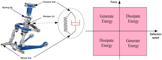
Figure 1.
Suspension system (left) and Speed-Effort Rule (right).
The overall objectives are then to provide a good vibration isolation when driving on uneven roads, ensuring passenger comfort (which is related to the human sensitivity to road vibrations) and road holding (the ability to keep the tyre in contact with the ground).
Along with the strong development of the automotive industry during past decades, the suspension system has also evolved continuously to be able to meet the requirements of this industry and of the customers. Several types of suspension systems have been designed, in particular the controlled (active and semi-active) suspensions. The suspension types can be characterized by the damper Speed Effort Rule (SER) with the suspension deflection speed as input and and the damping force as output, as represented in Figure 1. This leads to the following classification:
- Passive Suspension: it can only dissipate energy (the SER plot only concerns the quadrants 2 and 3). The mechanical characteristics of the components (springs and dampers) are fixed to guarantee a proper vibration isolation.
- Semi-active suspension: in such systems the damper can be controlled in real-time in order to adjust the damping properties, and handle the trade-off between vehicle safety and passengers comfort. However they can only dissipate energy. They provide the best trade-off between performance improvements and energy efficiency.
- Active suspension: it can generate and dissipate energy. However, while they are able to improve both ride and stability, active suspension systems requires an external energy source to control the vehicle motion.
In this paper, we focus on semi-active suspension only, which has gained more and more attention due to its global efficiency (in term of damping property and energy consumption).
2.2. Semi-Active Suspensions
Below some of the main technologies of semi-active dampers in the market are presented:
- Electro-hydraulic Dampers: the damping property can be controlled through the use of electronic valves that modify the oil circulation between the damper chambers [11,12]. Typically, the damping coefficient varies continuously and linearly with the area of the valve. An application of Electro-hydraulic Dampers were developed in [13] with SOBEN.
- Pneumatic damper: these actuators are a challenging technology where the damping is modified by a pressure pump that manipulates the flow resistance of a gas. In this kind of suspension, elasticity and viscosity are strictly coupled, and hard to be managed [11].
- Magneto-Rheological damper (MR damper): It exploits the physical properties of MR fluids [14,15]) whose viscosity can be changed from a magnetic field. When a magnetic field (e.g., generated by an electric current through a coil) is applied to the fluid, the particles form chains, and the fluid viscosity changes, leading to change of the damping coefficient of the suspension system. This kind of dampers allows to use different control strategies to adapt them to the desired performance objectives by providing the suitable electric current. MR damper is already used in some luxury and sport cars such as Ferrari, Audi TT, R8, Cadillac …
- Electro-Rheological damper (ER damper): it is similar to an MR dampers. It is filled by an ER fluid, which is a mixture of oil and micron sized particles sensitive to electric field. Therefore, as the electric field changes, the volume of the ER fluid changes and thus the damping coefficient of these dampers changes. This is controlled by adjusting the electric field [16,17]. This kind of damper is used in the INOVE test-bench developed in Gipsa-Lab (Grenoble, France) together with Soben [18] for the vehicle vertical dynamics study and analysis. As illustration, the SER diagram of the Electro-Rheological semi-active damper of the INOVE Car is given in Figure 2 from real data: on the left the Force-Deflection diagram and on the right the Force-Velocity one. As seen, the characteristics do depend on the control level given by the electrical field (in practice this is a PWM signal to control the voltage).
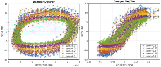 Figure 2. Force/Position (left) and Force/Velocity (right) characteristics of the ER Semi-active damper-INOVE testbed (GIPSA-lab, Grenoble).
2.3. Vehicle Modeling
Vehicle systems are very complex systems composed of many components such as the engine, gearbox, clutch, wheels, suspensions, shock absorber, brakes and many other elements. Dynamical models of such systems are very complex, highly nonlinear, since their behavior can change a lot during driving situations.
In the studies dedicated to suspension systems, the model must catch the dynamical behavior of the car. Such a model can be obtained through physical equations as described in dedicated books (see [19,20]), or using dedicated softwares as Simcenter Amesim (Siemens), CarSim (Mechanical Simulation Corporation), Dymola (Dassault Systems) …).
Since this paper is concerned with suspension systems, we are interested in vertical dynamics modeling only, such as the quarter model, the half car or the full vertical vehicle model presented in what follows. Note that for simplicity, the time-dependence of the considered variables is omitted.
2.3.1. Vertical Quarter Car Model
The (simple) quarter car model is usually represented as in Figure 3 and is composed by the following components:
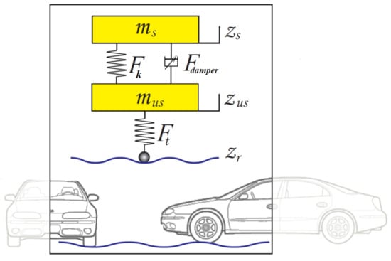
Figure 3.
Quarter car model of an automotive suspension system.
- Sprung mass:
- represents a quarter of the chassis body. The variable is the vertical displacement around the equilibrium point of .
- Unsprung mass:
- represents the wheel and the tire of the vehicle. The variable is the vertical displacement around the equilibrium point of .
- Suspension:
- composed by a spring and a damper represented by the spring (and damper ) forces (resp.).
- Tire:
- modeled by a spring with the stiffness coefficient .
- Road profile:
- the disturbance input.
The dynamical equations of the quarter car model as seen on Figure 3 are governed by:
where the spring force , and the vertical tire force are defined as:
with the suspension deflection.
The damper force , can be represented in several ways. It can be a:
- control input:
- , as usual in many studies dedicated to active suspension
- controlled variable damping:
- , where is indeed the control input [2,21].
- non linear model:
- there are several types of damper models in the literature, as seen in [9,10,17]). Among others the following one allows to consider the specific non-linearities of semi-active ER/MR dampers:
- The tanh function allows to model the bi-viscous behavior.
- (, , , ) are constant parameters. , are dedicated to the hysteresis behavior.
- is a controllable term depending on the current (MR damper) or voltage (ER damper) input.
Remark 1.
- A first or second order dynamics can be added to the controlled term in (4) in order to account for the internal damper dynamics. These dynamic properties can even be non linear w.r.t. the control level [22].
- Some quarter-car models do also consider a tire damping coefficient but this can usually be neglected, since the tire damping is very low.
2.3.2. Vertical Half Vehicle Model
Vertical half vehicle models are the natural extension of the vertical quarter car model. It simply involves an additional dynamic: the pitch () or roll () motion.
As an illustration, the nonlinear model involving roll dynamic is simply given by Equation (5) and Figure 4,
where the index holds for {left,right}, are the suspension forces, are the tire forces, and is the roll inertia. denotes the front axle length as shown on Figure 4. and are the chassis bounce and pitch at the center of gravity; and are the front and rear unsprung masses bounce respectively.
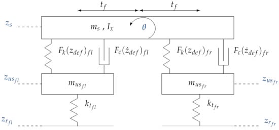
Figure 4.
Half car suspension model (roll oriented).
2.3.3. Lateral Vehicle Model
The bicycle model is widely widespread in the automotive literature. It allows to treat the lateral and yaw dynamics and is mainly involved when car stability is to be controlled.
In the context of this paper, the lateral motion is considered in several studies dedicated to suspension system, in particular considering the yaw-roll model for heavy vehicles with active suspension [23,24,25], or in the studies dedicated to variable geometry suspension [26,27,28,29,30]. Obviously, it is used too in studies dedicated to the integrated control of the suspension, steering and braking actuators (see for instance [31]).
An usual simplified version of the single track (bicycle) model is shown in Figure 5) (a more complete one is available in [19]) and is described as in:
where and are the (global) lateral tire forces of the front and the rear wheels (axle), respectively. denotes the side slip angle at the vehicle center of gravity. This model is highly nonlinear since it involves nonlinear lateral tire forces (that may be represented usin Pacejka or Dugoff tire models) and depends on the longitudinal vehicle velocity v.
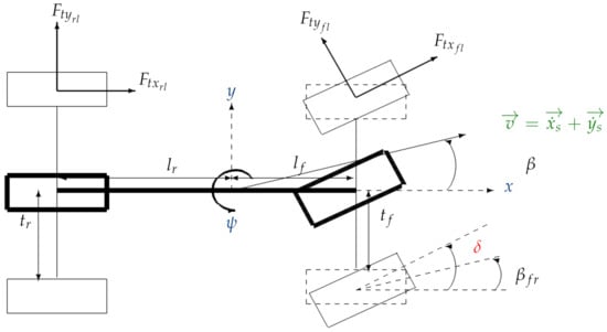
Figure 5.
Single track (bicycle) model of the lateral dynamics.
For lateral control design the above model is often linearized assuming:
- Linear lateral tire friction curve, i.e.,where and are the linear stiffness of the lateral tire characteristics at the front and rear, respectively.
- Small slip angles ( and ):where denotes the vehicle yaw, and denote the side slip angle at the front and rear. is the steering angle of the front wheel.
Then, under these considerations, the linearized model is given by (where the vehicle speed v is a model parameter):
Since this model depends on the vehicle speed v, many works involving this model use now an LPV version of the bicycle model
2.3.4. Full Vertical Vehicle Model
The full car 7 degree-of-freedom (DOF) vertical model (see Figure 6) is used to represent the complete vehicle vertical dynamics. It involves the chassis dynamics (vertical (), roll () and pitch() at the center of gravity), and the vertical displacements of the wheels at the front/rear ()-left/right corner (). The vertical 7 DOF full-car model is governed by the following dynamic equations:
where is the mass of the chassis, are the moments of inertia of the sprung mass around the longitudinal and lateral axis, respectively, h is the height of center of gravity (COG). are COG-front, rear, left, right distances, respectively. are the longitudinal and lateral accelerations. is the vertical force disturbance.
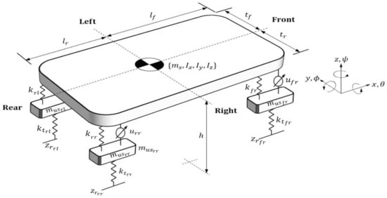
Figure 6.
Full vertical vehicle model.
The tire and suspension forces ( and resp.) can be represented in the ways explained previously for the quarter-car model.
The sprung mass positions at each vehicle corner can be easily derived from the vehicle equations of motions and are given by:
for which we can write and assuming that the roll and pitch angles are small enough.
2.3.5. About Road Profiles
The road profile is a key variable of the vertical dynamics since it induces the suspension motion. Often some basic input signals are used as bumps, sinusoïdal or swept sin signals. Nevertheless the types of road profile have been classified by the International Organization for Standardization (ISO) [32]. Therefore, for simulation and design purpose, it can be assumed that the road profile is represented as:
where is white noise, and a and b are coefficients that depend on the road type. The vehicle speed dependency is needed to state the variations of the spectrum of the road input according to the car velocity.
It is worth noting that using a road profile model is indeed possible since the information on the type of road profile may be obtained using some adaptive road profile estimator, as proposed in [33].
3. An Taxonomic Overview on Studies about (LPV) Suspension Control According to the Types of Actuators and Considered Models
From the previous section, it can be seen that several types of models can be considered in order to develop a suspension control strategy.
The studies dedicated to suspension control can be organized according to the chart presented in Figure 7, where are emphasized the control structure layer, then the type of suspension which have been considered, and finally the models which are used to compute the control solution.
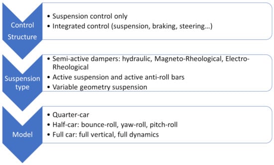
Figure 7.
Overview on suspension studies.
According to this chart, Table 1 details the list of studies that have been carried out in this framework, which is commented in the sequel.

Table 1.
List of studies carried out on suspension control.
3.1. Suspension Control Only
Such a problem has been handled for three different classes of systems: the semi-active suspension systems, the active ones (including the active anti-roll bar for heavy vehicles), and the variable-geometry suspensions.
As shown in many studies, [2,10], the control design for semi-active dampers is complex due to the dissipativity constraint on the damper. Such a constraint can be smartly handled through LPV technics, where the parameter(s) represent an anti-active control [36], or are related to the non linear model of such a constraints [48]. It is worth noting that, in the case of variable geometry suspensions the considered model includes the lateral and vertical motions since the aim is mainly to prove the interest of such suspensions on car stability [26,27,28,29,30].
3.2. Integrated Control
This framework does consider the coordination between various actuators, including the suspension system, in order to enhance the vehicle performances (mainly the stability). The classical considered subsystems are the front/rear steering, and the left/right+front/rear brakes and dampers. A short analysis of the literature contribution in that filed is summarized below.
- Semi-active suspension:
- The interaction of other actuators (namely the steering and braking ones) together with semi-active suspensions has been very few considered in the literature, while this is probably very relevant for future generations of cars [31,105,106].
- Active-suspension and anti-roll bars:
- Most of the studies do consider the combined use of several active components (steering, braking and suspension), some of them with active anti-roll bars when heavy vehicles are concerned. The core of the multivariable control is then to coordinate the use of these actuators, according to the driving situations, the on-line objectives, the presence of sensor/actuator faults/failures [107,108,109,110,111,112,113,114,115,116,117,118,119,120,121,122,123,124,125,126,127] …
- variable geometry suspensions:
- In the works carried out by Peter Gaspar and their colleagues, the variable geometry suspension control is linked to steering and braking control in order to further improve car stability, i.e., the yaw and lateral motions [119,128,129,130].
4. The LPV Approach: Aim and Solution
This part presents briefly the LPV approach including the optimization problem to be solved, with a specific focus on the methods and formulations that may be of high interest in suspension control.
Definition 1.
A dynamical LPV system can be expressed by the following state space equations:
where express the states of the system, are the exogenous inputs, the control input, controlled outputs, hold for the system’s measurements. , , , , , , , and . (convex set) is a vector of time varying parameters.
The assumptions on are:
- varies in the set of continuously differentiable parameter curves and is known or measurable.
- is bounded, i.e., .
- The system matrices , etc. are continuous functions on .
4.1. Why Use the LPV Approach?
Linear Parameter Varying (LPV) systems have been the topic are many works in the two last decade. Not only within theoretical papers, but also in various fields of applications. It is worth mentioning that the International Federation of Automatic Control (IFAC) society [131] has launched in 2015 the series of Workshops on Linear Parameter Varying Systems (LPVS), in the framework of the TC 2.2. Linear Control Systems.
Today the LPV approach is known to be well-suited to:
- Represent the system non linearities as varying parameters
- Ensure varying control performances through the use of different parameters to consider the variations of environmental conditions or to get adaptive real-time performance.
However, the additional complexity due to the varying parameters requires specific theoretical tools, in particular for stability analysis. Recent studies have then concerned model identification, stability/stabilization and control design, in the context of affine, polynomial or rational LPV systems. One of the main interests in control design is to allow for using linear analysis and control synthesis (, ) through reliable optimization tools as Linear Matrix Inequalities or non-smooth algorithms.
4.1.1. LPV Modeling for Non Linear Systems
The most well known use of LPV approach is the application to non linear systems. Indeed there are different ways to convert a non linear systems into an LPV one.
The first one is the historical method, referred to as the gain-scheduled control, which aims at doing a Jacobian Linearization of the non linear system around the set of operating conditions. This leads to a set of LTI models along a grid of parameter values as illustrated in Figure 8.
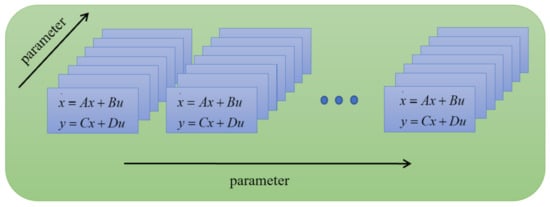
Figure 8.
A grid-based LPV model [132].
The second one is to rewrite the non linearities as varying parameters. It is worth noting that if the non linearities involve state variables the system is referred to as quasi-LPV (and is of course not equivalent to the non linear model). Note that this is sometimes called “non linearity embedding”. The clue for qLPV modeling is the application of the Linear Differential Inclusion theorem as stated below. Let us consider the non linear system:
Suppose that, for each x, w and t, there is a matrix s.t.:
where .
As said in [133]:
“Then of course every trajectory of the nonlinear system (14) is also a trajectory of the LDI defined by (15). If we can prove that every trajectory of the LDI defined by (15) has some property (e.g., converges to zero), then a fortiori we have proved that every trajectory of the nonlinear system (14) has this property."
Let us illustrate the case of LPV modeling with two cases:
- The quarter car vehicle suspension model:
- Recall that the semi-active nonlinear MR damper model (4) is given by:
- The bicycle model:
- In many lateral control problems (in particular for autonomous vehicles) the LPV bicycle model is appropriate, since the speed v deeply influences the dynamical behavior. Moreover, compared to the LPV quarter vertical model above, the parameter is not state dependent, then the model should be LPV and not qLPV. Additionally, in this case, the v parameter does not directly enter linearly in the system description, but as and . Then, if a polytopic approach is chosen for control synthesis, the LPV model would be of the form:where and .Notice that, if the longitudinal motion is considered, the vehicle speed will be a state variable and the above model a qLPV one.
4.1.2. LPV Adaptive Control
One of the key interests of the LPV approach is its high flexibility degree to make the performances of the closed-loop systems varying in real-time. Indeed, following the design method, the matrices of the controller will be scheduled from the parameter values, which will lead to parameter-dependent state matrices of the closed-loop systems.
A “basic” illustration of the control framework is presented in Figure 9. In such a scheme the LPV plant model is interconnected with and , some input and output parameter dependent weighting functions, in order to get the LPV generalized plant (which will be used for control design as seen later). is the controller to be synthetized, solving an optimization problem. It is worth noting that such a methodology allows to introduce parameter-dependent weighting functions that do characterize varying performances function of the parameter variations.
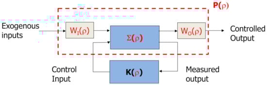
Figure 9.
LPV General Control Configuration.
This formulation allows to guarantee several types of real-time adaptation of the closed-loop performances, according to the type of considered parameters. Some of the interesting cases are:
- To handle the variations of environmental conditions, as the road conditions, the driver, other vehicles … for road vehicles;
- To provide a fault-scheduling control, i.e., to schedule the controller w.r.t to sensors/actuators/system fault estimations in order to reconfigure the control on-line to bring back the system from a faulty and possibly unsafe critical situation to a safe (but eventually degraded) one;
- To introduce high-level parameters that will be selected to allow the system adaptation, for instance changing the performances from comfort to safety in road vehicles, or providing an on-line control allocation for a Multi-Input Multi-Output (MIMO) system.
Let illustrate the following case where the suspension control is tuned on-line to enhance comfort or road handling. In [127], the suspension control design aims at providing performance adaptation though the use of parameter varying weighting functions in the framework, as illustrated in the control scheme in Figure 10:
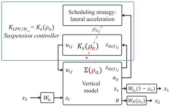
Figure 10.
Diagram block of the LPV/ suspension control.
Here the weighting functions have been defined as:
- selected to reduce the bounce amplification of the suspended mass motion () between Hz.
- which attenuates the roll bounce amplification in low frequencies.
- which limits the control signal.
The main objective of the proposed strategy is then to improve passenger comfort when there is no risk. However thanks to a smart adaption dangerous, various driving situations (with large lateral accelerations) can be handled using the following scheduling policy:
- In normal driving situations, the lateral acceleration is low, consequently, the parameter tends to 0. In this case, the LPV/ suspension control focuses on improving passenger comfort by reducing the chassis displacement and acceleration.
- When , the roll motion caused by high lateral accelerations is penalized to reduce the load transfer bounce and enhance roadholding, so the stability and safety of the vehicle are improved.
4.2. LPV/ Control Synthesis
A complete overview of the synthesis and implementation complexity of LPV approaches can be found in [1]. For each approach, the complexity of LPV controller existence conditions is determined in terms of the size of LMIs and the number of decision variables. Note that the obtained controller is an LPV Dynamic Output Feedback Controller.
Note that the robust control design methodology being within the framework, the generalized plant model includes, not only the plant model, but also the weighting functions used for performance and robustness requirements.
The interconnection of the plant model together with the weighting functions and , leads to the LPV generalized plant (see Figure 9):
Now, an LPV controller is written under the following structure
Definition 2.
An LPV Controller can be described in the following form:
where define the states of the LPV controller, , , and .
The objective of the synthesis is to find an LPV controller of the form (18) such that the closed-loop system is quadratically stable and that, for a given positive real , the induced- norm of the operator mapping w into z is bounded by i.e.,
The design step usually consists of minimizing satisfying (19).
The LPV synthesis concerns the design of a global controller that guarantees both stability and performance for all scheduling parameters defined in the predefined set . There are two approaches based on Quadratic and Parameter-Dependent Lyapunov Functions. In the quadratic approach, only the bounds on the scheduling parameter are taken into consideration (i.e., the parameter can vary as fast as possible) while in the parameter-dependent approach, further information on parameter rate is used in the synthesis. Henceforth, the latter approach is less conservative.
The problem formulation for control design consists of applying the Bounded Real Lemma to the closed-loop system, which will lead to an infinite set of LMIs to solve (due to the infinite possible values of the scheduling parameters).
Different approaches to reduce this problem into a finite number of LMIs are commonly used:
- Polytopic solution ([134]): A polytopic system is a convex combination of systems defined at each vertex of a polytope given by the bounds on the scheduling parameters. The synthesis of such a controller can be made in the framework of based on the LMI solution for polytopic systems (the framework of quadratic stabilization). This can be applied to LPV systems with an affine dependence on the parameters only.
- Linearizations on a gridded domain (grid-based LPV) ([135]): they are obtained through Jacobian linearization at each grid point. Each linearization approximates the system’s dynamics in the vicinity of a particular grid point, and the grid of linearizations captures the system’s parameter dependence implicitly. Hence, linearization based LPV models do not require any special dependence on the parameter vector.
- Linear Fractional Transformations (LFT) ([136,137]): The LFT models have state matrices that are rational functions of the parameter. Hence, their dependence on the parameter vector is modelled explicitly.
5. LPV Methodologies for Suspension Control: Types of Scheduling Strategies
There have been many papers on that topic in the two last decades as illustrated in Figure 11. These studies can be classified as shown in Table 2.
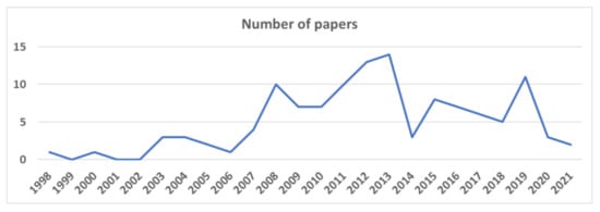
Figure 11.
Chronological evolution of the number of papers about LPV for suspension systems (total number = 121 papers).
Table 2.
Type of LPV methods considered for suspension and integrated control.
- The type of controlled components: either the suspension is used only, or several actuators are used together (suspension/steering/braking);
- The type of LPV methods: the main categories either to use LPV for gain-scheduling or qLPV approaches so to consider nonlinear systems, or to develop an adaptive control (the parameter playing the role of the scheduling strategy for performance adaptation).
In the sequel, the considered problems are briefly presented and then the LPV methodologies considered in these works are explained following the classification presented in Table 2 above.
5.1. About Control Problems
The overall objectives related to the suspension system are comfort and road holding. While the first concerns the passenger (and driver) pleasure, the later influences the drive safety. The control objectives usually consider these objectives (a single one or a combination of both) as well as structural constraints (the dissipative characteristic of the damper and the end-stop phenomena. Moreover, if the damper is subject to faults, e.g., oil leakages, the development of control techniques with fault-tolerance features is required to maintain the reliability of the automotive suspension system (comfort and road holding).
On the other hand, the control structure in terms of actuators can be of different types according to the type of:
- Considered vertical model (quarter-car, half-car or full car);
- Controlled components: either the suspension is used only, or several actuators are used together (suspension/steering/braking).
An important focus is put in the next sections on how the LPV approaches have been developed in this field, in particular on:
- The type of LPV methods: the main categories are either to use qLPV approaches so to consider nonlinear systems, or to develop an adaptive control (the parameter playing the role of the scheduling strategy for performance adaptation);
- The type and role of the scheduling parameters.
5.2. Suspension Control Problems
- LPV for non linear systems:
- Many papers have been devoted to suspension systems control using a qLPV formulation in order to represent the non linearities of the suspension. This may concern the spring stiffness, but is indeed mainly about the damping characteristics which can be distinguished by an hysteresis, different behaviours in release/compression phases, and variable force saturation according to the control level …. Therefore, most of the papers for which the objective is to account for these non linearities only do consider either:
- The deflection and/or deflection velocity as varying parameters, as well as the spring stiffness and damping non linearities, that could concern active and semi-active suspension, for instance as in [21,34,58,74,75,77,80,86,88,95,98];
- An LPV mathematical representation of the dissipativity property of semi-active dampers as in [2,13,15,35,36,37,40,41,42,44,45,46,47,48,49,50,51,52,60,62,66,67,81].
In that context, the parameters that are used for scheduling strategy are the variables directly involved in the suspension model, so the deflection and/or deflection velocity as varying parameters, as well as the spring stiffness and damping non linearities, that could be used to handle the properties of the suspension [21,34,58,74,75,77,80,86,88,95,98]. - LPV for adaptive control:
- There are many studies where the potential of the LPV approach is further exploited considering adaptive performances property. This can be handled using parameter dependent weights (in the robust control framework in and contexts) and/or using scheduling parameters in order to activate some control inputs (for over actuated systems) or to schedule the control to a monitor parameter (fault estimation, driver reaction, road variations …).In that context, the (many) different types of parameters have been used for scheduling strategies include, as detailed below:
- The variables directly involved in the suspension model, so the deflection and/or deflection velocity as varying parameters, as well as the spring stiffness and damping non linearities, in order to get adaptive performances in case the physical limits are reached [38,39,71,76,78,79,99,102,103];
- A saturation monitor/indicator for semi-active suspension to get some kind of anti-active property (an extension of anti wind-up one) [2,36,37,59,82,92];
- The damper force or control level in particular in case of observer design [22,61,63,64];
- The body mass [43,56,65,68];
- The vehicle motion: speed, accelerations, tire deformations, roll/pitch load transfers … [23,24,25,69,83,84,87,89,91];
- The road profile (in order to get a road-adaptive control) [12,53,54,55,70,138];
- The estimated sensor/actuator faults to get fault accommodation or fault tolerant property [17,57,85,93,94,96,97,100].
5.3. Integrated Control
Another problem consists of considering several types of actuators that may allow to control the (longitudinal and/or lateral + vertical) vehicle dynamics, in order to use to suspension system capabilities for road holding and handling. There have been several studies in that topic usually referred-to-as global chassis control [31,140,141]. Therefore, in terms of models, all studies do consider either an half-car model or a full car one, in order to tackle the coupling between yaw and roll motions. In that context most studies are considering consider active suspension or anti-roll bars.
- LPV for non linear systems:
- Only few works do handle the case of semi-active suspension (which needs to consider the dissipativity constraint of the suspension system as the dedicated works on that topic) [31,105,106] or the case of variable geometry suspensions [119,128,129,130].
- LPV for adaptive control:
- In the case of integrated control, the LPV approach can allow a better coordination of the different actuators according to the vehicle state, the driving conditions, the driver inputs, the effects of sensor/actuator faults … So most of the works do not consider qLPV model from non linear characteristics but do consider parameters defined from a monitoring or a supervisory task.It is proposed here to distribute the studies in three classes depending on the scheduling strategy:
- Class 1:
- The parameters are defined from the vehicle performances (slip condition, car stability, load transfer, vehicle speed, road conditions, actuator performances …) [105,106,109,110,111,116,119,120,122,123,124,127,129,130];
- Class 2:
- Parameters are defined from the vehicle performances BUT do emphasize Passive Fault Tolerant property through fault accommodation. [107,121,125];
- Class 3:
- Parameters are defined from the vehicle performances AND from a Fault Diagnosis scheme, allowing to get an Active Fault Tolerant Control [104,108,112,113,114,115,117,118,126,128,139].
6. Concluding Remarks
The LPV approach has been studied in numerous research studies in recent years on the suspension control problem. This has shown the great interest and considerable potential of the LPV control formulation to deal with various suspension systems in various vehicle architectures.
According to the types of studies presented before, a summary on the scheduling strategies is shown in Table 3 to emphasize the key use of scheduling parameters.
Table 3.
Type and role of scheduling parameters.
A very interesting LPV adaptive scheme concerns the case when a Fault Detection and Diagnosis (FDD) scheme is available, for which the LPV approach is then shown to be a nice tool to derive Fault Tolerant reconfigurable Controller (FTC) with:
- Fault-scheduling control design in order to ensure fault compensation;
- Fault-adaptive performances to satisfy the actuator constraints and to provide desired performance degradation;
- Fault-accommodation MIMO control to modify on-line the control allocation.
Therefore, from this review, a generic scheme of the LPV control approaches presented in this review can be stated as in Figure 12. This scheme emphasized the 2 main layers of such a control scheme: the monitoring one (which may include observers or FDD algorithms), and the vehicle dynamic controller one (which is a scheduled function of some information given by the monitoring layer). This interaction is one of the main interests of the proposed LPV architecture.
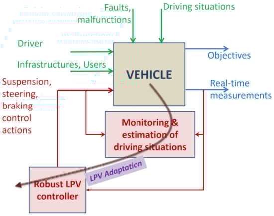
Figure 12.
LPV generic control scehme.
Finally it is worth noticing that the LPV approach, while ensuring theoretical stability and performances proofs, has shown to be very illustrative, efficient and practically reliable for various application fields and industrial sectors: Mechanics, Mechatronics, Robotics, Energy, Power & Hydraulic plants, Consumer electronics, Biology, Ecology, Health. This will its main asset for further expansion of this approach in academic and industrial research studies.
Funding
This research received no external funding.
Conflicts of Interest
The author declares no conflict of interest.
Abbreviations
The following abbreviations are used in this manuscript:
| ECU | Electronic Control Unit |
| ER | Electro-Rheological |
| FDD | Fault Detection and Diagnosis |
| FTC | Fault Tolerant Control |
| IRI | International Roughness Index |
| ISO | International Organization for Standardization |
| LFT | Linear Fractional Transformation |
| LMI | Linear Matrix Inequality |
| LPV | Linear Parameter Varying |
| LTI | Linear Time Invariant |
| MIMO | Multi-Input Multi-Output |
| MR | Magneto-Rheological |
| RMS | Root Mean Square |
| SER | Speed Effort Rule |
References
- Hoffmann, C.; Werner, H. A Survey of Linear Parameter-Varying Control Applications Validated by Experiments or High-Fidelity Simulations. IEEE Trans. Control. Syst. Technol. 2015, 23, 416–433. [Google Scholar] [CrossRef]
- Poussot-Vassal, C.; Spelta, C.; Sename, O.; Savaresi, S.; Dugard, L. Survey and performance evaluation on some automotive semi-active suspension control methods: A comparative study on a single-corner model. Annu. Rev. Control. 2012, 36, 148–160. [Google Scholar] [CrossRef]
- Li, P.; Nguyen, A.T.; Du, H.; Wang, Y.; Zhang, H. Polytopic LPV approaches for intelligent automotive systems: State of the art and future challenges. Mech. Syst. Signal Process. 2021, 161, 107931. [Google Scholar] [CrossRef]
- Zin, A. Sur la Commande Robuste de Suspensions Automobiles en vue du Contrôle Global de Châssis. Ph.D. Thesis, Institut National Polytechnique de Grenoble, Grenoble, France, 2005. [Google Scholar]
- Poussot-Vassal, C. Robust Multivariable Linear Parameter Varying Control of Automotive Chassis. Ph.D. Thesis, Université de Grenoble, Saint-Martin-d’Hères, France, 2008. [Google Scholar]
- Aubouet, S. Semi-Active SOBEN Suspensions Modeling and Control. Ph.D. Thesis, Institut National Polytechnique de Grenoble-INPG, Grenoble, France, 2010. [Google Scholar]
- Do, A.L. Approche LPV Pour la Commande Robuste de la Dynamique des Véhicules: Amélioration Conjointe du Confort et de la Sécurité. Ph.D. Thesis, Université de Grenoble, Grenoble, France, 2010. [Google Scholar]
- Nguyen, M.Q. LPV Approaches for Modelling and Control of Vehicle Dynamics: Application to a Small Car Pilot Plant with ER Dampers. Ph.D. Thesis, Université de Grenoble, Grenoble, France, 2016. [Google Scholar]
- Pham, T.P. LPV Observer and Fault-Tolerant Control of Vehicle Dynamics: Application to an Automotive Semi-Active Suspension System. Ph.D. Thesis, Université de Grenoble, Grenoble, France, 2019. [Google Scholar]
- Savaresi, S.M.; Poussot-Vassal, C.; Spelta, C.; Sename, O.; Dugard, L. Semi-Active Suspension Control Design for Vehicles; Butterworth-Heinemann: Boston, MA, USA, 2010; pp. 203–206. [Google Scholar] [CrossRef]
- Spelta, C. Design and Applications of Semi-Active Suspension Control Systems. Ph.D. Thesis, Politecnico di Milano, Dipartimento di Elettronica e Informazione, Milano, Italy, 2008. [Google Scholar]
- Hong, K.S.; Sohn, H.C.; Hedrick, J.K. Modified skyhook control of semi-active suspensions: A new model, gain scheduling, and hardware-in-the-loop tuning. J. Dyn. Syst. Meas. Control. 2002, 124, 158–167. [Google Scholar] [CrossRef]
- Aubouet, S.; Dugard, L.; Sename, O.; Poussot-Vassal, C.; Talon, B. Semi-active H∞/LPV control for an industrial hydraulic damper. In Proceedings of the 2009 European Control Conference (ECC), Budapest, Hungary, 23–26 August 2009; pp. 3628–3633. [Google Scholar] [CrossRef]
- Jeyasenthil, R.; Yoon, D.S.; Choi, S.B.; Kim, G.W. Robust semiactive control of a half-car vehicle suspension system with magnetorheological dampers: Quantitative feedback theory approach with dynamic decoupler. Int. J. Robust Nonlinear Control. 2021, 31, 1418–1435. [Google Scholar] [CrossRef]
- de Jesus Lozoya-Santos, J.; Morales-Menendez, R.; Tudón-Martínez, J.C.; Sename, O.; Dugard, L.; Ramirez-Mendoza, R. Control Strategies for an Automotive Suspension with a MR Damper. IFAC Proc. Vol. 2011, 44, 1820–1825. [Google Scholar] [CrossRef]
- Jeyasenthil, R.; Choi, S. A novel semi-active control strategy based on the quantitative feedback theory for a vehicle suspension system with magneto-rheological damper saturation. Mechatronics 2018, 54, 36–51. [Google Scholar] [CrossRef]
- Morato, M.M.; Pham, T.P.; Sename, O.; Dugard, L. Development of a simple ER damper model for fault-tolerant control design. J. Braz. Soc. Mech. Sci. Eng. 2020, 42, 2764–2775. [Google Scholar] [CrossRef]
- SOBEN. société SOBEN, Home Page. Available online: https://soben.fr/ (accessed on 21 July 2021).
- Kiencke, U.; Nielsen, L. Automotive Control Systems: For Engine, Driveline, and Vehicle; Springer-Verlag: Berlin/Heidelberg, Germany, 2005. [Google Scholar]
- Gillespie, T.D. Fundamentals of Vehicle Dynamics; SAE: Warrendale, PA, USA, 1992. [Google Scholar]
- Nguyen, M.; da Silva, J.G.; Sename, O.; Dugard, L. A state feedback input constrained control design for a 4-semi-active damper suspension system: A quasi-LPV approach. IFAC-PapersOnLine 2015, 48, 259–264. [Google Scholar] [CrossRef]
- Pham, T.P.; Sename, O.; Dugard, L.; Vu, V.T. LPV Force Observer Design and Experimental Validation from a Dynamical Semi-Active ER Damper Model. IFAC-PapersOnLine 2019, 52, 60–65. [Google Scholar] [CrossRef]
- Gaspar, P.; Szaszi, I.; Bokor, J. Fault-Tolerant Control Structure to Prevent the Rollover of Heavy Vehicles. IFAC Proc. Vol. 2003, 36, 441–446. [Google Scholar] [CrossRef]
- Gáspár, P.; Szabó, Z.; Bokor, J.; Németh, B. Anti-roll Bars for Rollover Prevention. In Robust Control Design for Active Driver Assistance Systems: A Linear-Parameter-Varying Approach; Springer International Publishing: Cham, Switzerland, 2017; pp. 119–134. [Google Scholar] [CrossRef]
- Vu, V.; Sename, O.; Dugard, L.; Gaspar, P. An Investigation into the Oil Leakage Effect Inside the Electronic Servo-valve for an H∞/LPV Active Anti-roll Bar System. Int. J. Control Autom. Syst. 2019, 17, 2917–2928. [Google Scholar] [CrossRef]
- Németh, B.; Gáspár, P. Enhancement of vehicle stability based on variable geometry suspension and robust LPV control. In Proceedings of the 2011 IEEE/ASME International Conference on Advanced Intelligent Mechatronics (AIM), Budapest, Hungary, 3–7 July 2011; pp. 253–258. [Google Scholar] [CrossRef]
- Németh, B.; Gáspár, P. Design of variable-geometry suspension for driver assistance systems. In Proceedings of the 2012 20th Mediterranean Conference on Control Automation (MED), Barcelona, Spain, 3–6 July 2012; pp. 1111–1116. [Google Scholar] [CrossRef]
- Németh, B.; Gáspár, P. Control Design of Variable-Geometry Suspension Considering the Construction System. IEEE Trans. Veh. Technol. 2013, 62, 4104–4109. [Google Scholar] [CrossRef][Green Version]
- Németh, B.; Gáspár, P. LPV-based Variable-Geometry Suspension Control Considering Nonlinear Tyre Characteristics. IFAC-PapersOnLine 2015, 48, 61–66. [Google Scholar] [CrossRef]
- Németh, B.; Gáspár, P. Nonlinear analysis and control of a variable-geometry suspension system. Control. Eng. Pract. 2017, 61, 279–291. [Google Scholar] [CrossRef]
- Fergani, S. Robust Multivariable Control for Vehicle Dynamics. Ph.D. Thesis, Université de Grenoble, Grenoble, France, 2014. [Google Scholar]
- ISO. ISO 8608:2016, Mechanical Vibration—Road Surface Profiles—Reporting of Measured Data; Technical Report; International Organization for Standardization: Geneva, Switzerland, 2016. [Google Scholar]
- Tudón-Martínez, J.C.; Fergani, S.; Sename, O.; Martinez, J.J.; Morales-Menendez, R.; Dugard, L. Adaptive Road Profile Estimation in Semiactive Car Suspensions. IEEE Trans. Control. Syst. Technol. 2015, 23, 2293–2305. [Google Scholar] [CrossRef]
- Gaspar, P.; Szabo, Z.; Bokor, J. Estimating Road Roughness by Using A Linear Parameter Varying Model. IFAC Proc. Vol. 2003, 36, 103–108. [Google Scholar] [CrossRef]
- Poussot-Vassal, C.; Sename, O.; Dugard, L.; Gáspár, P.; Szabó, Z.; Bokor, J. A Lpv Based Semi-Active Suspension Control Strategy. IFAC Proc. Vol. 2007, 40, 106–111. [Google Scholar] [CrossRef]
- Poussot-Vassal, C.; Sename, O.; Dugard, L.; Gáspár, P.; Szabó, Z.; Bokor, J. A new semi-active suspension control strategy through LPV technique. Control. Eng. Pract. 2008, 16, 1519–1534. [Google Scholar] [CrossRef]
- Meisami-Azad, M.; Mohammadpour, J.; Grigoriadis, K.M. Anti-Windup LPV Control of Magneto-Rheological Dampers. In Proceedings of the ASME 2009 Dynamic Systems and Control Conference, Hollywood, CA, USA, 12–14 October 2009; Volume 2, pp. 817–824. [Google Scholar] [CrossRef]
- Aubouet, S.; Dugard, L.; Sename, O. H∞/LPV observer for an industrial semi-active suspension. In Proceedings of the 2009 IEEE Control Applications, (CCA) Intelligent Control, (ISIC), ST. Petersburg, Russia, 8–10 July 2009; pp. 756–763. [Google Scholar] [CrossRef]
- Do, A.L.; Spelta, C.; Savaresi, S.; Sename, O.; Dugard, L.; Delvecchio, D. An LPV control approach for comfort and suspension travel improvements of semi-active suspension systems. In Proceedings of the 49th IEEE Conference on Decision and Control (CDC), Atlanta, GA, USA, 15–17 December 2010; pp. 5560–5565. [Google Scholar] [CrossRef]
- Do, A.; Sename, O.; Dugard, L. An LPV control approach for semi-active suspension control with actuator constraints. In Proceedings of the 2010 American Control Conference, Baltimore, MD, USA, 30 June–2 July 2010; pp. 4653–4658. [Google Scholar] [CrossRef]
- de Jesus Lozoya-Santos, J.; Sename, O.; Dugard, L.; Morales-Menendez, R.; Ramirez-Mendoza, R. A LPV Quarter of Car with Semi-active Suspension Model including Dynamic Input Saturation. IFAC Proc. Vol. 2010, 43, 68–75. [Google Scholar] [CrossRef]
- Do, A.L.; Gomes da Silva, J.M.; Sename, O.; Dugard, L. Control design for LPV systems with input saturation and state constraints: An application to a semi-active suspension. In Proceedings of the 2011 50th IEEE Conference on Decision and Control and European Control Conference, Orlando, FL, USA, 12–15 December 2011; pp. 3416–3421. [Google Scholar] [CrossRef]
- Esmaeili, J.S.; Akbari, A.; Mirzaei, M. LPV H2 control of semi-active suspensions. In Proceedings of the 2nd International Conference on Control, Instrumentation and Automation, Shiraz, Iran, 27–29 December 2011; pp. 725–730. [Google Scholar] [CrossRef]
- Poussot-Vassal, C.; Spelta, C.; Sename, O.; Savaresi, S.; Dugard, L. Survey on Some Automotive Semi-Active Suspension Control Methods: A Comparative Study on a Single-Corner Model. IFAC Proc. Vol. 2011, 44, 1802–1807. [Google Scholar] [CrossRef]
- Do, A.; Sename, O.; Dugard, L.; Soualmi, B. Multi-objective optimization by genetic algorithms in H∞/LPV control of semi-active suspension. IFAC Proc. Vol. 2011, 44, 7162–7167. [Google Scholar] [CrossRef]
- Sename, O.; Do, A.; Poussot-Vassal, C.; Dugard, L. Some LPV approaches for semi-active suspension control. In Proceedings of the 2012 American Control Conference (ACC), Montreal, QC, Canada, 27–29 June 2012; pp. 1567–1572. [Google Scholar] [CrossRef]
- Lozoya-Santos, J.d.J.; Morales-Menendez, R.; Ramírez Mendoza, R.A. Control of an Automotive Semi-Active Suspension. Math. Probl. Eng. 2012, 2012, 218106. [Google Scholar] [CrossRef]
- Do, A.L.; Sename, O.; Dugard, L. LPV Modeling and Control of Semi-active Dampers in Automotive Systems. In Control of Linear Parameter Varying Systems with Applications; Springer US: Boston, MA, USA, 2012; pp. 381–411. [Google Scholar] [CrossRef]
- Félix-Herrán, L.; Mehdi, D.; Rodríguez-Ortiz, J.D.; Soto, R.; Ramírez-Mendoza, R. H∞ control of a suspension with a magnetorheological damper. Int. J. Control. 2012, 85, 1026–1038. [Google Scholar] [CrossRef]
- Tudón-Martínez, J.C.; Morales-Menendez, R.; Ramírez-Mendoza, R.; Sename, O.; Dugard, L. Fault Tolerant Control in a Semi-active Suspension. IFAC Proc. Vol. 2012, 45, 1173–1178. [Google Scholar] [CrossRef]
- Do, A.L.; Poussot-Vassal, C.; Sename, O.; Dugard, L. LPV Control Approaches in View of Comfort Improvement of Automotive Suspensions Equipped with MR Dampers. In Robust Control and Linear Parameter Varying Approaches: Application to Vehicle Dynamics; Springer: Berlin/Heidelberg, Germany, 2013; pp. 183–212. [Google Scholar] [CrossRef]
- Tudón-Martínez, J.C.; Varrier, S.; Sename, O.; Morales-Menendez, R.; Martinez, J.; Dugard, L. Fault tolerant strategy for semi-active suspensions with LPV accommodation. In Proceedings of the 2013 Conference on Control and Fault-Tolerant Systems (SysTol), Nice, France, 9–11 October 2013; pp. 631–636. [Google Scholar] [CrossRef]
- Tudón-Martínez, J.C.; Fergani, S.; Varrier, S.; Sename, O.; Dugard, L.; Morales-Menendez, R.; Ramírez-Mendoza, R. Road Adaptive Semi-Active Suspension in an Automotive Vehicle using an LPV Controller. IFAC Proc. Vol. 2013, 46, 231–236. [Google Scholar] [CrossRef]
- Lozoya-Santos, J.D.-J.; Morales-Menendez, R.; Ramirez-Mendoza, R.A.; Sename, O.; Dugard, L. Adaptive Semi-Active Suspension Design Using Gain-Scheduling. IFAC Proc. Vol. 2013, 46, 845–850. [Google Scholar] [CrossRef]
- Fergani, S.; Menhour, L.; Sename, O.; Dugard, L.; D’Andrea Novel, B. A new LPV/H∞ semi-active suspension control strategy with performance adaptation to roll behavior based on non linear algebraic road profile estimation. In Proceedings of the 52nd IEEE Conference on Decision and Control, Firenze, Italy, 10–13 December 2013; pp. 3511–3516. [Google Scholar] [CrossRef]
- Tudón-Martínez, J.C.; Hernández-Alcántara, D.; Morales-Menendez, R. Semi-Active Suspension Control with LPV Mass Adaptation. IFAC-PapersOnLine 2015, 48, 67–72. [Google Scholar] [CrossRef]
- Nguyen, M.; Sename, O.; Dugard, L. An LPV Fault Tolerant control for semi-active suspension-scheduled by fault estimation. IFAC-PapersOnLine 2015, 48, 42–47. [Google Scholar] [CrossRef]
- Nguyen, M.Q.; da Silva, J.M.G.; Sename, O.; Dugard, L. Semi-active suspension control problem: Some new results using an LPV/H∞ state feedback input constrained control. In Proceedings of the 2015 54th IEEE Conference on Decision and Control (CDC), Osaka, Japan, 15–18 December 2015; pp. 863–868. [Google Scholar] [CrossRef]
- Fleps-Dezasse, M.; Ahmed, M.M.; Brembeck, J.; Svaricek, F. Experimental evaluation of Linear Parameter-Varying semi-active suspension control. In Proceedings of the 2016 IEEE Conference on Control Applications (CCA), Buenos Aires, Argentina, 19–22 September 2016; pp. 77–84. [Google Scholar] [CrossRef]
- Santos, L.; de Jesús, J.; Tudon-Martinez, J.C.; Ramirez-Mendoza, R.A. LPV Control for a Semi-Active Suspension Quarter of Car-One Parameter Case. MATEC Web Conf. 2016, 81, 08003. [Google Scholar] [CrossRef]
- Nguyen, M.Q.; Sename, O.; Dugard, L. Comparison of observer approaches for actuator fault estimation in semi-active suspension systems. In Proceedings of the 2016 3rd Conference on Control and Fault-Tolerant Systems (SysTol), Barcelona, Spain, 7–9 September 2016; pp. 227–232. [Google Scholar] [CrossRef]
- Tudon-Martinez, J.C.; Hernandez-Alcantara, D.; Sename, O.; Morales-Menendez, R.; Lozoya-Santos, J.D. Parameter-Dependent H∞ Filter for LPV Semi-Active Suspension Systems. IFAC-PapersOnLine 2018, 51, 19–24. [Google Scholar] [CrossRef]
- Pham, T.P.; Sename, O.; Dugard, L. Real-time Damper Force Estimation of Vehicle Electrorheological Suspension: A NonLinear Parameter Varying Approach. IFAC-PapersOnLine 2019, 52, 94–99. [Google Scholar] [CrossRef]
- Morato, M.M.; Sename, O.; Dugard, L.; Nguyen, M.Q. Fault estimation for automotive Electro-Rheological dampers: LPV-based observer approach. Control. Eng. Pract. 2019, 85, 11–22. [Google Scholar] [CrossRef]
- Wu, J.; Zhou, H.; Liu, Z.; Gu, M. A load-dependent PWA-H∞ controller for semi-active suspensions to exploit the performance of MR dampers. Mech. Syst. Signal Process. 2019, 127, 441–462. [Google Scholar] [CrossRef]
- Morato, M.M.; Normey-Rico, J.E.; Sename, O. Sub-optimal recursively feasible Linear Parameter-Varying predictive algorithm for semi-active suspension control. IET Control. Theory Appl. 2020, 14, 2764–2775. [Google Scholar] [CrossRef]
- Németh, B.; Gáspár, P. Ensuring performance requirements for semiactive suspension with nonconventional control systems via robust linear parameter varying framework. Int. J. Robust Nonlinear Control. 2020. [Google Scholar] [CrossRef]
- Zhang, X.; Weng, R.; Wang, J.; Nie, L.; Han, Y.; Chen, H. Switched LPV Modeling and H2 Control for Hybrid Suspension with Mass Variation. In Proceedings of the 2020 Chinese Automation Congress (CAC), Shanghai, China, 6–8 November 2020; pp. 7644–7649. [Google Scholar] [CrossRef]
- Basargan, H.; Mihály, A.; Gáspár, P.; Sename, O. Adaptive Semi-Active Suspension and Cruise Control through LPV Technique. Appl. Sci. 2021, 11, 290. [Google Scholar] [CrossRef]
- Fialho, I.; Balas, G. Adaptive vehicle suspension design using LPV methods. In Proceedings of the 37th IEEE Conference on Decision and Control (Cat. No.98CH36171), Tampa, FL, USA, 18 December 1998; Volume 1, pp. 469–474. [Google Scholar] [CrossRef]
- Fialho, I.J.; Balas, G.J. Design of Nonlinear Controllers for Active Vehicle Suspensions Using Parameter-Varying Control Synthesis. Veh. Syst. Dyn. 2000, 33, 351–370. [Google Scholar] [CrossRef]
- Gaspar, P.; Szaszi, I.; Bokor, J. The Application of Linear Parameter Varying Control to Active Suspension Design. IFAC Proc. Vol. 2003, 36, 437–442. [Google Scholar] [CrossRef]
- Gaspar, P.; Szaszi, I.; Bokor, J. Active Suspension Design using LPV Control. IFAC Proc. Vol. 2004, 37, 565–570. [Google Scholar] [CrossRef]
- Zin, A.; Sename, O.; Gaspar, P.; Dugard, L.; Bokor, J. An LPV/H∞ Active Suspension Control for Global Chassis Technology: Design and Performance Analysis. In Proceedings of the 2006 American Control Conference, Minneapolis, MN, USA, 14–16 June 2006; pp. 2945–2950. [Google Scholar] [CrossRef]
- Gaspar, P.; Szederkenyi, G. Combined LPV and nonlinear control of an active suspension system. In Proceedings of the 2007 IEEE International Symposium on Industrial Electronics, Vigo, Spain, 4–7 June 2007; pp. 215–220. [Google Scholar] [CrossRef]
- Poussot-Vassal, C.; Drivet, A.; Sename, O.; Dugard, L.; Ramirez-Mendoza, R. A Self Tuning Suspension Controller for Multi-body Quarter Vehicle Model. IFAC Proc. Vol. 2008, 41, 3410–3415. [Google Scholar] [CrossRef]
- Zin, A.; Sename, O.; Gaspar, P.; Dugard, L.; Bokor, J. Robust LPV–H∞ control for active suspensions with performance adaptation in view of global chassis control. Veh. Syst. Dyn. 2008, 46, 889–912. [Google Scholar] [CrossRef]
- Onat, C.; Kucukdemiral, I.; Sivrioglu, S.; Yuksek, I.; Cansever, G. LPV gain-scheduling controller design for a non-linear quarter-vehicle active suspension system. Trans. Inst. Meas. Control. 2009, 31, 71–95. [Google Scholar] [CrossRef]
- Fritsch, O.; Koch, G.; Lohmann, B. Deflection adaptive LPV control of an active suspension system. In Proceedings of the 2009 European Control Conference (ECC), Budapest, Hungary, 23–26 August 2009; pp. 4404–4409. [Google Scholar] [CrossRef]
- Ucun, L.; Küçükdemiral, I.B.; Delibaşı, A.; Cansever, G. LPV control active suspension system. In Proceedings of the 2011 IEEE International Conference on Mechatronics, Istanbul, Turkey, 13–15 April 2011; pp. 116–121. [Google Scholar] [CrossRef]
- Han, S.; Lee, S.M.; Jung, H.; Park, J.H. Constrained H∞ Control for Active Suspension Systems with Aperiodic Sampling: A Looped Functional Approach. In Proceedings of the 2019 6th International Conference on Control, Decision and Information Technologies (CoDIT), Paris, France, 23–26 April 2019; pp. 796–800. [Google Scholar] [CrossRef]
- Fleps-Dezasse, M.; Bünte, T.; Svaricek, F.; Brembeck, J. LPV feedforward control of semi-active suspensions for improved roll stability. Control. Eng. Pract. 2018, 78, 1–11. [Google Scholar] [CrossRef]
- Gaspar, P.; Szaszi, I.; Bokor, J. Rollover Stability Control for Heavy Vehicles by Using LPV Model. IFAC Proc. Vol. 2004, 37, 673–678. [Google Scholar] [CrossRef]
- Gaspar, P.; Szaszi, I.; Bokor, J. Improving rollover stability with active suspensions by using an LPV method. IFAC Proc. Vol. 2004, 37, 781–786. [Google Scholar] [CrossRef]
- Gáspár, P.; Szabó, Z.; Bokor, J. Design of integrated control for road vehicles using LPV methods. In Proceedings of the 18th Mediterranean Conference on Control and Automation, MED’10, Marrakech, Morocco, 23–25 June 2010; pp. 1247–1252. [Google Scholar] [CrossRef]
- Li, P.; Lam, J.; Cheung, K.C. Velocity-dependent multi-objective control of vehicle suspension with preview measurements. Mechatronics 2014, 24, 464–475. [Google Scholar] [CrossRef]
- Fergani, S.; Menhour, L.; Sename, O.; Dugard, L.; D’Andrea Novel, B. LPV/H∞ suspension robust control adaption of the dynamical lateral load transfers based on a differential algebraic estimation approach. IFAC-PapersOnLine 2016, 49, 440–447. [Google Scholar] [CrossRef]
- Gáspár, P.; Szabó, Z.; Bokor, J. Actuator fault detection for suspension system. IFAC Proc. Vol. 2009, 42, 1426–1431. [Google Scholar] [CrossRef]
- Fujita, T.; Fukao, T.; Kinoshita, T.; Itagaki, N. Semi-Active Suspension Improving Both Ride Comfort and Handling Feel. IFAC Proc. Vol. 2013, 46, 225–230. [Google Scholar] [CrossRef]
- Fergani, S.; Sename, O.; Dugard, L. A LPV/H∞ fault tolerant control of vehicle roll dynamics under semi-active damper malfunction. In Proceedings of the 2014 American Control Conference, Portland, OR, USA, 4–6 June 2014; pp. 4482–4487. [Google Scholar] [CrossRef]
- Nguyen, M.Q.; Sename, O.; Dugard, L. A motion-scheduled LPV control of full car vertical dynamics. In Proceedings of the 2015 European Control Conference (ECC), Linz, Austria, 15–17 July 2015; pp. 129–134. [Google Scholar] [CrossRef]
- Fleps-Dezasse, M.; Brembeck, J. LPV Control of Full-Vehicle Vertical Dynamics using Semi-Active Dampers. IFAC-PapersOnLine 2016, 49, 432–439. [Google Scholar] [CrossRef]
- Fleps-Dezasse, M.; Svaricek, F.; Brembeck, J. Damper Fault-Tolerant Linear Parameter-Varying Semi-Active Suspension Control. IFAC-PapersOnLine 2017, 50, 8592–8599. [Google Scholar] [CrossRef]
- Morato, M.M.; Sename, O.; Dugard, L. LPV-MPC Fault Tolerant Control of Automotive Suspension Dampers. IFAC-PapersOnLine 2018, 51, 31–36. [Google Scholar] [CrossRef]
- Morato, M.M.; Nguyen, M.Q.; Sename, O.; Dugard, L. Design of a fast real-time LPV model predictive control system for semi-active suspension control of a full vehicle. J. Frankl. Inst. 2019, 356, 1196–1224. [Google Scholar] [CrossRef]
- Morato, M.M.; Sename, O.; Dugard, L. Design and Analysis of Several State-Feedback Fault-Tolerant Control Strategies for Semi-Active Suspensions. IFAC-PapersOnLine 2019, 52, 48–53. [Google Scholar] [CrossRef]
- Fleps-Dezasse, M.; Svaricek, F.; Brembeck, J. Design and Experimental Assessment of an Active Fault-Tolerant LPV Vertical Dynamics Controller. IEEE Trans. Control. Syst. Technol. 2019, 27, 1267–1274. [Google Scholar] [CrossRef]
- Onat, C.; Kucukdemiral, I.B.; Sivrioglu, S.; Yuksek, I. LPV Model Based Gain-scheduling Controller for a Full Vehicle Active Suspension System. J. Vib. Control. 2007, 13, 1629–1666. [Google Scholar] [CrossRef]
- Gaspar, P.; Szabo, Z.; Szederkenyi, G.; Bokor, J. Two-level controller design for an active suspension system. In Proceedings of the 2008 16th Mediterranean Conference on Control and Automation, Ajaccio, France, 25-27 June 2008; pp. 439–444. [Google Scholar] [CrossRef]
- Gaspar, P.; Szabo, Z.; Bokor, J. The design of a reconfigurable suspension control system based on an FDI filter. In Proceedings of the 2008 16th Mediterranean Conference on Control and Automation, Ajaccio, France, 25–27 June 2008; pp. 445–450. [Google Scholar] [CrossRef]
- Gaspar, P.; Szabo, Z.; Bokor, J. Design of reconfigurable and fault-tolerant suspension systems based on LPV methods. In Proceedings of the 2008 47th IEEE Conference on Decision and Control, Cancun, Mexico, 9–11 December 2008; pp. 5384–5389. [Google Scholar] [CrossRef]
- Gáspár, P.; Szederkényi, G.; Szabó, Z.; Bokor, J. The Design of a Two-Level Controller for Suspension Systems. IFAC Proc. Vol. 2008, 41, 3386–3391. [Google Scholar] [CrossRef]
- Gáspár, P.; Szabó, Z.; Szederkényi, G.; Bokor, J. Design of a two-level controller for an active suspension system. Asian J. Control. 2012, 14, 664–678. [Google Scholar] [CrossRef]
- Gáspár, P.; Szabó, Z. Design of a Hierarchical Controller for Suspension Systems. In Robust Control and Linear Parameter Varying Approaches: Application to Vehicle Dynamics; Springer: Berlin/Heidelberg, Germany, 2013; pp. 311–328. [Google Scholar] [CrossRef]
- Fergani, S.; Sename, O.; Dugard, L. Performances improvement through an LPV/H∞ control coordination strategy involving braking, semi-active suspension and steering Systems. In Proceedings of the 2012 IEEE 51st IEEE Conference on Decision and Control (CDC), Maui, HI, USA, 10–13 December 2012; pp. 4384–4389. [Google Scholar] [CrossRef]
- Fergani, S.; Sename, O.; Dugard, L. An LPV/H∞ Integrated Vehicle Dynamic Controller. IEEE Trans. Veh. Technol. 2016, 65, 1880–1889. [Google Scholar] [CrossRef]
- Gaspar, P.; Szabo, Z.; Bokor, J. The Design of an Integrated Control System in Heavy Vehicles Based on an LPV Method. In Proceedings of the 44th IEEE Conference on Decision and Control, Seville, Spain, 12–15 December 2005; pp. 6722–6727. [Google Scholar] [CrossRef]
- Gaspar, P.; Szaszi, I.; Bokor, J. Reconfigurable control structure to prevent the rollover of heavy vehicles. Control. Eng. Pract. 2005, 13, 699–711. [Google Scholar] [CrossRef]
- Gáspár, P.; Szabó, Z.; Bokor, J.; Poussot-Vassal, C.; Sename, O.; Dugard, L. Towards Global Chassis Control by Integrating the Brake and Suspension Systems. IFAC Proc. Vol. 2007, 40, 563–570. [Google Scholar] [CrossRef]
- Poussot-Vassal, C.; Sename, O.; Dugard, L.; Gáspár, P.; Szabó, Z.; Bokor, J. Attitude and Handling Improvements Through Gain-scheduled Suspensions and Brakes Control. IFAC Proc. Vol. 2008, 41, 2075–2080. [Google Scholar] [CrossRef]
- Gáspár, P.; Szabó, Z.; Bokor, J. An Integrated Vehicle Control with Actuator Reconfiguration. IFAC Proc. Vol. 2008, 41, 2087–2092. [Google Scholar] [CrossRef]
- Gáspár, P.; Szabó, Z.; Bokor, J. A Fault-Tolerant Vehicle Control Design. IFAC Proc. Vol. 2008, 41, 8540–8545. [Google Scholar] [CrossRef]
- Gáspár, P.; Szabó, Z.; Bokor, J. LPV-based reconfigurable chassis design. In Proceedings of the 2009 European Control Conference (ECC), Budapest, Hungary, 23–26 August 2009; pp. 3634–3639. [Google Scholar] [CrossRef]
- Gáspár, P.; Szabó, Z.; Bokor, J. LPV design of reconfigurable and integrated control for road vehicles. In Proceedings of the 2011 50th IEEE Conference on Decision and Control and European Control Conference, Orlando, FL, USA, 12–15 December 2011; pp. 2505–2510. [Google Scholar] [CrossRef]
- Gáspár, P.; Szabó, Z.; Bokor, J. LPV design of adaptive integrated control for road vehicles. IFAC Proc. Vol. 2011, 44, 662–667. [Google Scholar] [CrossRef]
- Poussot-Vassal, C.; Sename, O.; Dugard, L.; Gáspár, P.; Szabó, Z.; Bokor, J. Attitude and handling improvements through gain-scheduled suspensions and brakes control. Control. Eng. Pract. 2011, 19, 252–263. [Google Scholar] [CrossRef]
- Szabó, Z.; Gáspár, P.; Bokor, J. Design of Integrated Vehicle Chassis Control Based on LPV Methods. In Control of Linear Parameter Varying Systems with Applications; Springer US: Boston, MA, USA, 2012; pp. 513–534. [Google Scholar] [CrossRef]
- Gáspár, P.; Németh, B.; Bokor, J. Design of a supervisory integrated control for driver assistance systems. In Proceedings of the 2012 IEEE 51st IEEE Conference on Decision and Control (CDC), Maui, HI, USA, 10–13 December 2012; pp. 5022–5027. [Google Scholar] [CrossRef]
- Cáspár, P.; Németh, B.; Bokor, J. Design of an integrated control for driver assistance systems based on LPV methods. In Proceedings of the 2012 American Control Conference (ACC), Montreal, QC, Canada, 27–29 June 2012; pp. 2916–2921. [Google Scholar] [CrossRef]
- Fergani, S.; Sename, O.; Dugard, L. A LPV/H∞ Global Chassis Controller for performances Improvement Involving Braking, Suspension and Steering Systems. IFAC Proc. Vol. 2012, 45, 363–368. [Google Scholar] [CrossRef]
- Gáspár, P. Design of Integrated Control for Road Vehicles. In Robust Control and Linear Parameter Varying Approaches: Application to Vehicle Dynamics; Springer: Berlin/Heidelberg, Germany, 2013; pp. 213–235. [Google Scholar] [CrossRef]
- Fergani, S.; Sename, O.; Dugard, L. A LPV suspension control with performance adaptation to roll behavior, embedded in a global vehicle dynamic control strategy. In Proceedings of the 2013 European Control Conference (ECC), Zurich, Switzerland, 17–19 July 2013; pp. 1487–1492. [Google Scholar] [CrossRef]
- Fergani, S.; Sename, O.; Dugard, L. A new LPV/H∞ Global Chassis Control through load transfer distribution and vehicle stability monitoring. IFAC Proc. Vol. 2013, 46, 809–814. [Google Scholar] [CrossRef]
- Fergani, S.; Menhour, L.; Sename, O.; Dugard, L.; Novel, B.D. Full vehicle dynamics control based on LPV/H∞ and flatness approaches. In Proceedings of the 2014 European Control Conference (ECC), Strasbourg, France, 24–27 June 2014; pp. 2346–2351. [Google Scholar] [CrossRef]
- Fergani, S.; Sename, O.; Dugard, L.; Gáspár, P. Further development on the LPV fault tolerant control for vehicle dynamics. IFAC-PapersOnLine 2015, 48, 24–29. [Google Scholar] [CrossRef]
- Gáspár, P.; Szabó, Z.; Bokor, J.; Németh, B. Design of Integrated Vehicle Control. In Robust Control Design for Active Driver Assistance Systems: A Linear-Parameter-Varying Approach; Springer International Publishing: Cham, Switzerland, 2017; pp. 161–186. [Google Scholar] [CrossRef]
- Fergani, S.; Menhour, L.; Sename, O.; Dugard, L.; D’Andréa-Novel, B. Integrated vehicle control through the coordination of longitudinal/lateral and vertical dynamics controllers: Flatness and LPV/-based design. Int. J. Robust Nonlinear Control. 2017, 27, 4992–5007. [Google Scholar] [CrossRef]
- Gáspár, P.; Németh, B. Integrated control design for driver assistance systems based on LPV methods. Int. J. Control. 2016, 89, 2420–2433. [Google Scholar] [CrossRef]
- Németh, B.; Gáspár, P.; Fényes, D.; Bokor, J. Robust control design for the integration of steering and torque vectoring using a variable-geometry suspension system. In Proceedings of the 2017 American Control Conference (ACC), Seattle, WA, USA, 24–26 May 2017; pp. 291–296. [Google Scholar] [CrossRef]
- Németh, B.; Fényes, D.; Gáspár, P.; Bokor, J. Coordination of Independent Steering and Torque Vectoring in a Variable-Geometry Suspension System. IEEE Trans. Control. Syst. Technol. 2019, 27, 2209–2220. [Google Scholar] [CrossRef]
- IFAC. International Federation of Automatic Control, Home Page. Available online: https://www.ifac-control.org/ (accessed on 20 July 2021).
- Hjartarson, A.; Balas, G.; Packard, A.; Seiler, P. LPV Tools: Introduction to a new data structure for LPV systems. In ESA-CNES-DLR Workshop: Linear Parameter Varying Control: A Framework for Adaptable Space Systems; Archive ouverte HAL: Lyon, France, 2014. [Google Scholar]
- Boyd, S.; Ghaoui, L.E.; Feron, E.; Balakrishnan, V. Linear Matrix Inequalities in System and Control Theory; Studies in Applied and Numerical Mathematics, SIAM: New Delhi, India, 1994. [Google Scholar]
- Apkarian, P.; Gahinet, P.; Becker, G. Self-scheduled H∞ control of linear parameter-varying systems: A design example. Automatica 1995, 31, 1251–1261. [Google Scholar] [CrossRef]
- Wu, F. Control of lInear Parameter Varying Systems. Ph.D. Thesis, University of California at Berkeley, Berkeley, CA, USA, 1995. [Google Scholar]
- Apkarian, P.; Gahinet, P. A Convex Characterization of Gain-Scheduled H∞ Controllers. IEEE Trans. Autom. Contr. 1995, 40, 853–864. [Google Scholar] [CrossRef]
- Apkarian, P.; Adams, R. Advanced gain-scheduling techniques for uncertain systems. IEEE Trans. Autom. Contr. 1998, 6, 21–32. [Google Scholar] [CrossRef]
- Fialho, I.; Balas, G. Road adaptive active suspension design using linear parameter-varying gain-scheduling. IEEE Trans. Control. Syst. Technol. 2002, 10, 43–54. [Google Scholar] [CrossRef]
- Sename, O.; Tudon-Martinez, J.; Fergani, S. LPV methods for fault-tolerant vehicle dynamic control. In Proceedings of the 2013 Conference on Control and Fault-Tolerant Systems (SysTol), Nice, France, 9–11 October 2013; pp. 116–130. [Google Scholar] [CrossRef]
- Vivas-López, C.A.; Hernández-Alcantara, D.; Tudón-Martínez, J.C.; Morales-Menendez, R. Review on Global Chassis Control. IFAC Proc. Vol. 2013, 46, 875–880. [Google Scholar] [CrossRef]
- Chokor, A. Design of Several Centralized and Decentralized Multilayer Robust Control Architectures for Global Chassis Control. Ph.D. Thesis, Université de Technologie de Compiègne, Compiègne, France, 2010. [Google Scholar]
Publisher’s Note: MDPI stays neutral with regard to jurisdictional claims in published maps and institutional affiliations. |
© 2021 by the author. Licensee MDPI, Basel, Switzerland. This article is an open access article distributed under the terms and conditions of the Creative Commons Attribution (CC BY) license (https://creativecommons.org/licenses/by/4.0/).