1. Introduction
GNSS provides 4D positioning (XYZT). Each satellite contains two rubidium and two cesium atomic clocks. They are monitored by an atomic clock on the ground, and the entire system is constantly calibrated to a universal time standard, Coordinated Universal Time (UTC). GNSS receivers determine the time T to within 100 billionths of a second without the cost of owning, operating and maintaining an atomic clock.
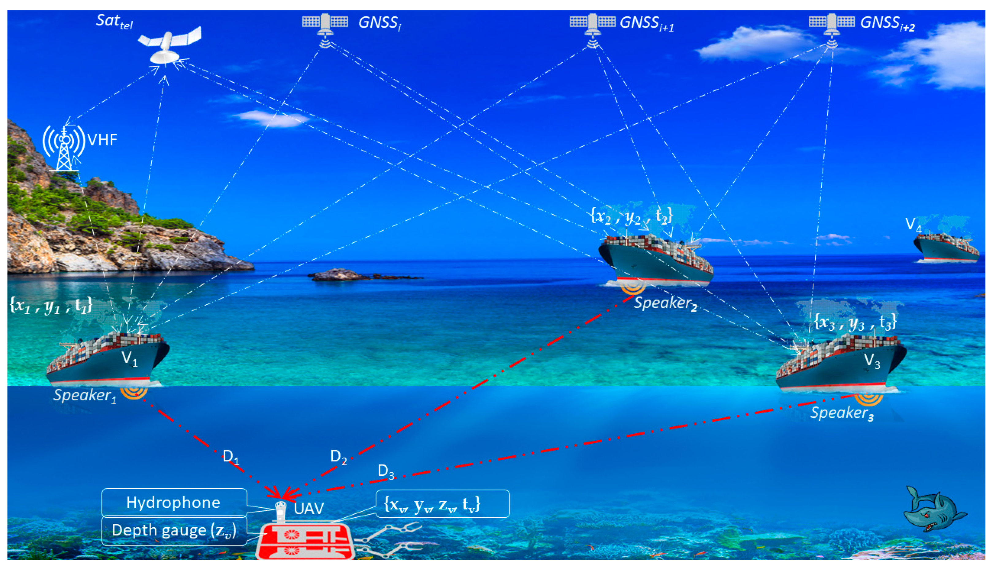
Of particular importance is the measurement of XYZT underwater. Similarly to measuring atmospheric pressure in air, you can measure water pressure and convert it to the depth of your dive, and, of course, transfer the measured time on the sea surface to the UAV (Underwater Autonomous Vehicle).
We assume that some surface vehicles are additionally equipped with an Acoustic Speaker, which transmits the XY coordinates of the vessel with an indication of accuracy and the time T of the vessel. Submarine vehicles determine their position by acoustic signals XYT from several surface acoustic sources using the Time of Arrival (ToA).
Detection of Spoofing for the Dynamic Underwater Positioning Systems (DUPS) based on vehicles retrofitted with acoustic speakers is an actual problem. Underwater spoofing works as follows: N acoustic speakers on N vehicels transmit the coordinates . GNSS signals are susceptible to interference due to their very low power (−130 dBm) and can be easily jammed by other sources, which may be accidental or intentional. The spoofer, like an underwater vehicle, receives these signals from N vessels, distorts and transmits them with increased acoustic power. If the level of the acoustic signal from the spoofer exceeds the level of the signal of the ship’s acoustic speaker, then the acoustic receiver will “catch” the false signal and, on this basis, it will calculate the false position. All will calculate the same coordinates, so the indication of the coincidence of coordinates from a pair of diversity receivers is an indication of spoofing detection.
It is necessary to highlight the promising design program of three companies: DARPA (Defense Advanced Research Projects Agency, 675 North Randolph Street, Arlington, VA 22203-2114, 703.526.6630), BAE Systems (British Aerospace) and the Charles Stark Draper Laboratory [
1,
2,
3,
4] (see the DUPS for example on
Figure 1).
Code division multiplexing (CDM) is a class of techniques in which multiple channels use simultaneously the same frequency spectrum. Omitting the analysis of the aforementioned multiplexing methods, we choose the code division multiplexing used in the global positioning system (GNSS CDMA).
In this article, we limit ourselves to considering only those DUPS in which the navigation receiver is acoustically passive. The receiver “listens” to the radioacoustic transponders, receives their messages and solves own the geographical coordinates of the acoustic speakers (OCEANEARS. The Finest Underwater Sound Systems//
https://Oceanears.com, accessed on 25 August 2021).
Section 2,
Section 3 and
Section 4 are actually a continuation of the reader’s introduction to trigonometric positioning calculations, respectively, in 1D, 2D and 3D space.
Section 5 introduces the necessary notation and basic definitions of spoofing. The algorithm of the main spoofing strategy is described in
Section 6. The interaction of the main elements of the explanation system in
Section 7. The two main algorithms for detecting spoofing are given in
Section 8 and
Section 9. Conclusions based on the article are given in
Section 10.
2. GNSS-like DUPS (Case 1D)
Suppose some ships are equipped with acoustic speakers broadcasting XYT at some frequency
. In this case, underwater vehicles, manned or unmanned (UAV), are able to position on the base of the XYT broadcast on board the UAV (
Figure 2) and measure the depth of the dive using a water pressure gauge with an error (1)
where
are unknown true UAV coordinates taken equal to
coordinates, that is,
or
. If the UAV is located exactly under the speaker
, then the positioning error reaches a minimum value (theoretically
ε = 0).
3. GNSS-like DUPS (Case 2D)
The basic principle of underwater positioning has been considered many times by various authors. Here we present a brief discussion of related work [
1,
2,
3] to make it easier to understand the meaning of this article. A typical EvoLogics LBL (long baseline) positioning system can be found in [
1]. LBL uses an array of base transponders mounted on the seabed: their exact location is known, so they are used as reference points to locate targets. In this LBL and the overwhelming majority of similar ones, the following principle of trilateration (linear triangulation) is used. Base transponders respond to acoustic interrogation signals from target-mounted transceivers with their own acoustic pulses, allowing the target transceiver to calculate its position by measuring the distance between it and each transponder of the base array.
In this article, we rely on a different principle: base transponders periodically send out acoustic signals, allowing the target receiver to measure the transit time of the signal from the transponder to the target receiver, provided that the clocks of the transponder and the target receiver are synchronized with some known accuracy.
The vessel is equipped with a GNSS receiver to accurately calibrate the base transponder array after deployment.
Suppose that there are at least three vehicles in the UAV sensitivity field (
Figure 3) equipped with acoustic speakers transmitting the parameters
at the frequency
.
M. Youngberg has patented this solution [
5,
6,
7,
8] (It should be emphasized here that our article is mainly based on the results described in [
5,
6,
7,
8]. In [
5], GIB (GPS intelligent buoys) involve groups of buoys that calculate their own position from the GPS and then send acoustic signals to the underwater vehicle as a basis for calculation of its position. In [
6], the device comprises at least one GIB which is drifting and/or autonomous and comprises one one-way communication receiver with one transmitter for transmitting positioning signals. GIB comprises at least one two-way transceiver for messaging signals. The paper [
7] uses buoys that act as mobile pseudoliths and transform the GPS radio service into an underwater acoustics-based service. Using this service, an unlimited number of users can independently locate and navigate underwater). Acoustic waves go from acoustic speakers to the receiver of UAV. Then the UAV computes its own position.
The vehicles in a state of normal traffic solve the XYT coordinates. The receiver of GNSS-like signals determines its own coordinates, if the UAV is retrofitted with a depth sensor .
In some applications, only the XY coordinates are significant, since Z can be determined by a depth gauge. In this case (2D) it can be shown (2)
describing the relationship of coordinates has the following solution (3)
4. GNSS-like DUPS (Case 3D)
In geometry, the three-dimensional problem of trilateration is to find the coordinates of the point of intersection of three spheres, which are determined by solving a system of equations. To simplify calculations, we assume that the centers of all three spheres lie in the z = 0 plane, one of them coincides with the origin. The imposed restrictions do not diminish the generality: any system of corresponding equations can be reduced to this form by passing to another coordinate system. In the original coordinate system transformations are applied to the solution in reduced coordinate system, inverse to those that allowed the original set of three points to be brought into line with these constraints.
Let us start with Equation (4) for three spheres
For a point (
x, y, z) that satisfies these equations, we must subtract the second from the first equation and find
x (5)
If the first two spheres intersect at more than one point, then
and substituting the expression
x into the equation of the first sphere, we obtain (6), which is the intersection of the first two spheres
Substitute
into the third sphere equation to find
y (7)
Knowing the
x and
y coordinates, you can find the z coordinate (8)
Thus, a given problem can have none, one or two solutions z.
Take the circle as the intersection of the first two spheres and find its intersection with the third sphere:
If the circle goes beyond the third sphere, then , where is the set of real numbers. In this case, the problem has no real solution.
If the circle touches the sphere at one point, then and the problem has one real solution.
If the circle intersects the sphere at two points, then where and the problem has two real solutions.
5. Notations and Definitions for GNSS-like Spoofing
GNSS professional users are becoming more and more aware that they have a problem or that they may have a problem. They suspect something is wrong, when they see anomalous behavior in their positioning domain. But how can they tell if they are being jammed or spoofed?
There is a wide range of spoofing attack scenarios and their features, as well as the results in testing against these scenarios. It gives recent examples of very dangerous, threatening behavior encountered in the field. In spoofing, the victim does not know that he received a false signal and determines the wrong time and place [
9,
10,
11,
12,
13]. DUPS remains the predominant navigation solution for both commercial and military underwater applications. However, proven threats to GNSS-like UPS from jamming, spoofing, and environmental blockages have convinced the military, as well as many commercial technology firms, that now is the time to find new navigation solutions that can enhance a security of GNSS-like UPS.
{xs, ys}—spoofer’s XY (zs = 0, because in this article, we limit ourselves to the surface spoofers only),
{xv, yv, zv}—victim’s XYZ, as measured by the victim (here “Victim = UAV”),
{}—victim’s XYZ, as measured by the spoofer,
{Δxv, Δyv, Δzv}—amendment of victim’s coordinates for taking away the victim from a given route,
—time of sending the signal from the i-th vehicle,
—time of signal arrival at the UAV hydrophone,
—signal propagation time the i-th vehicle to the UAV hydrophone.
6. The Strategy of Spoofing
The smart spoofer pre-listens to the environment (
Figure 4) and simulates signals from a GNSS-type UPS. It is desirable that at the moment of target acquisition the coordinates coincide, and then imitate the movement of the victim’s target along a given (fake) trajectory. It can be shown that a conventional repeater can be used as a simple spoofer with limited functionality sufficient to test the spoofing principle. Such a spoofer introduces the simplest distortion of the acoustic speaker signals, namely, introduces a signal delay (9) by the value
where
is the distance from the spoofer to the victim,
V is the speed of sound in sea water (
V ≈ 1530 m/s).
By solving the system of Equation (10) by analogy with (2) are the coordinates of the spoofer
. The system of equations
has the only solution under the condition
, that is, all the UAVs in the range of acoustic repeater define coordinates as
.
7. The Interaction of DUPS
Using (11), we calculate the coordinates of the target
The system of Equation (11) is written as (12)
Equation (12) is solved by numerical methods (13)
Due to the approximate nature of the measurement of pseudoranges (ρi ≈ cTi, ) the positioning accuracy {xv, yv} will depend on the number of speakers N.
The system of Equation (11) takes the form (14)
The solution (13) is carried out as (15)
Solving (15), we calculate {
xs,
ys}
Suppose the victim’s coordinates {
xv,
yv} are known. If the target does not use a barometric depth gauge to determine
, then
_i corrections can be determined so that the target receiver calculates false coordinates equal to the true ones (17)
If the speaker power is exceeded, the target switches to receiving a false signal, and the spoofer applies the target tracking strategy (18)
where
—target tracking.
8. The First Algorithm of Spoofing Detection Strategy for Anti-Spoofer Design
We mainly consider the results obtained in [
14,
15,
16,
17]. We installed a single hydrophone on the spoofing detector and the target may be in motion.
8.1. The Navigation Mode
The First Measurement (at the time t′).
The spoofing detector measures the coordinates of the hydrophone (19)
where
—unknown precise coordinates and
—calculated coordinates.
The Second Measurement (at the time t″).
The spoofing detector again measures the coordinates of the hydrophone (20)
where
—unknown precise coordinates of the hydrophone at the time
t″ and
—calculated coordinates of the hydrophone at the time
t″.
Calculating the distance travelled by a target in the time between two measurements.
The measured distance (21)
must be commensurate with the real distance (22) traveled by the vehicle over time (
t″ −
t′), i.e.,
8.2. The Spoofing Mode
The First Measurement (at the time t′).
The spoofing detector measures the coordinates of the hydrophone (23) as (19) and again as (20).
The measured distance (23) between the hydrophone at the time
t′ and the hydrophone at the time
t″
because all hydrophones calculate the same false coordinates and
must be incommensurable with the distance (24) traveled by the vehicle over time (
t″ −
t′), i.e.,
8.3. The Decisive Rule for the Detecting Spoofing
Comparing (22) and (24), we can write down the decisive rule (25)
where
—the discriminant determined on the basis of an experimental studies.
9. The Second Algorithm of Spoofing Detection Strategies for Anti-Spoofer Design
We installed two hydrophones
H′ and
H″ on the UAV as the spoofing detector at distance
D from each other (
Figure 5).
9.1. The Navigation Mode
The spoofing detector measures the coordinates (26) and (27) of the hydrophones
H′ and
H″
where (
) and (
)—unknown precise coordinates of the hydrophones
H′ and
H″;
and
—calculated coordinates.
The measured distance (28) between
H′ and
H″ is
where
D—the real distance between hydrophones.
9.2. The Spoofing Mode
As we have already noted, all hydrophones in the spoofing zone calculate the same false coordinates, so Equation (28) takes the form (29)
9.3. The Decisive Rule
Comparing (28) and (29), we can write down the decisive rule (30) for detecting spoofing
where
—the discriminant determined on the basis of an experimental studies.
10. The Comparison of Two Algorithms of Spoofing Detection Strategy for Anti-Spoofer Design
A distinctive feature of the first algorithm is the ability to install the system on the standard equipment of an underwater vehicle. However, such an installation assumes that the vehicle at the moment of detecting spoofing is in a state of motion with a certain minimum speed determined at the design stage.
The second algorithm is free from this drawback, but requires the installation of additional equipment in the form of a second hydrophone. A significant advantage of such a system is the operability of the algorithm at any speed of movement of the underwater vehicle (
Table 1).
11. Conclusions
This paper discusses the spoofing detection of DUPS by the use of single and dual hydrophones and the keys to solving the challenge of providing reliable positioning.
First, the authors briefly but scrupulously introduced the reader to the trigonometric calculations of one-dimensional, two-dimensional and three-dimensional positioning, after which they methodically provided the necessary notation and basic definitions of spoofing. An important section is the algorithm of the main spoofing strategy, and it is necessary to especially note the strict description of the interaction of the main elements of the system. The main thing in this article is two algorithms for detecting spoofing. At the end of the article, the authors presented in sufficient detail the main conclusions based on the materials of the article.
The authors would like to emphasize that this article is controversial for the following two main reasons.
1. At present, one of the most reputable research firms in the world, DARPA [
4], continues to develop underwater positioning systems based on moored buoys along the main most popular routes for underwater vehicles, both manned and unmanned.
2. Retrofitting vessels with additional hydroacoustic equipment will require significant international organizational measures and may turn out to be practically unrealizable.
The accessories necessary for the manufacture of systems for underwater acoustic “jamming” and/or “spoofing” are now widely available and this type of attack can be utilized by the military, but also by terrorists.
Further research should focus on a statistical study of the main traffic of sea traffic, including offshore, to determine the most attractive areas of the seas and oceans for the practical implementation of the described algorithms of Spoofing Detection Strategy for Anti-Spoofer Design.


 ,
, 


