Article

Evaluation of the Different Numerical Formats for HIL Models of Power Converters after the Adoption of VHDL-2008 by Xilinx

HCTLab Research Group, Universidad Autónoma de Madrid, 28049 Madrid, Spain
*
Author to whom correspondence should be addressed.
Electronics 2021, 10(16), 1952; https://doi.org/10.3390/electronics10161952
Submission received: 21 July 2021 / Revised: 10 August 2021 / Accepted: 11 August 2021 / Published: 13 August 2021

Abstract

:
Hardware in the loop is a widely used technique in power electronics, allowing to test and debug in real time (RT) at a low cost. In this context, field-programmable gate arrays (FPGAs) play an important role due to the high-speed requirements of RT simulations, in which area optimization is also crucial. Both characteristics, area and speed, are affected by the numerical formats (NFs) and their rounding modes. Regarding FPGAs, Xilinx is one of the largest manufacturers in the world, offering Vivado as its main design suite, but it was not until the release of Vivado 2020.2 that support for the IEEE NF libraries of VHDL-2008 was included. This work presents an exhaustive evaluation of the performance of Vivado 2020.2 in terms of area and speed using the native IEEE libraries of VHDL-2008 regarding NF. Results show that even though fixed-point NFs optimize area and speed, if a user prefers the use of floating-point NFs, with this new release, it can be synthesized—which could not be done in previous versions of Vivado. Although support for the native IEEE libraries of VHDL-2008 was included in Vivado 2020.2, it still lacks some issues regarding NF conversion during synthesis while support for simulation is not yet included.

1. Introduction

The hardware in the loop (HIL) technique has become a very popular approach for power electronics testing in recent years due to its safety and low-cost [1]. HIL allows the real-time emulation of the different parts of a system using digital hardware under non-invasive conditions [2,3]. HIL models reduce the cost of debugging, can avoid severe damages to real systems and finally reduce the overall test effort [4,5].
The recent inclusion of field-programmable gate arrays (FPGAs) in HIL techniques provoked a significant increase in the field of power electronics. FPGAs are capable of computing a great number of operations in parallel, thus leading to a low execution time [6,7,8]. This enables the computation of HIL simulations with integration steps of approximately hundreds of nanoseconds [9,10]. The ability to reach such small integration steps results in achieving a better accuracy and enabling the simulation of high-frequency switching converters; however, reaching this goal is not that easy due to the minimum latency required for the equation’s execution [11].
Therefore, not only the use of FPGAs is enough for the minimization of the integration time, but a designer should also consider other possible FPGA design constraints [12,13] such as, for example, numerical formats (NFs). The use of floating-point NF could result in more complex and slower hardware with respect to the use of fixed-point NF, or be even less accurate [14]; however, on the other hand, it requires less user design effort [13]. Furthermore, the design software considered is of great importance, while software such as MATLAB/Simulink [15] or the use of high-level languages such as HLS [16] decrease the users’ design effort, but they are not as efficient as using hard-coding like HDL languages [17,18], which generally ends up on slower and more complex hardware circuit simulations [2,19,20,21]. Recently, some commercial HIL platforms such as Typhoon HIL [20], Opal-RT [22] or the National Instruments RIO family [23] have appeared to implement HIL models, however, these programs are not generally user-transparent and do not allow the designer to optimize the resulting model. Consequently, in order to optimize the speed and area with the purpose of building a real-time low-cost HIL system, the designer should choose the optimal language, software and NF to ensure a minimal integration step and hardware elements: look up tables (LUTs), digital signal processors (DSPs) and flip-flops (FFs).
Xillinx is currently one of the world’s biggest FPGA manufacturers, offering Vivado as its main design suite for synthesis and implementation. Vivado allows the use of different languages for describing electronic systems, such as VHDL or Verilog. In this work, the VHDL-2008 standard is considered for that purpose. Even though VHDL-2008 is becoming widely used for hardware description, Vivado did not provide support for the fixed- and floating-point NF IEEE libraries of VHDL-2008, instead, the IEEE_proposed libraries of VHDL-93 had to be used while only fixed-point NF synthesis was supported. This drawback made the design process cumbersome and time-consuming and the user had to reprogram any desired characteristic which was not a default option. Furthermore, external files and user-defined libraries had to be used. The recently released Vivado 2020.2 included support for the fixed- and floating-point NF native IEEE libraries, in addition to the use of the VHDL-2008 standard. With this release, the design, synthesis and implementation will be less time-consuming when floating- or fixed-point NFs are involved, which results in a very attractive point for the designer.
The aim of this paper was to evaluate the performance of HIL models in Vivado 2020.2 using VHDL-2008 for hardware description and its native IEEE libraries. The performance of the model was evaluated in terms of area and speed regarding the different NFs available, particularly floating- and fixed-point NFs, and their intrinsic rounding and overflow modes. Results will be compared against the HIL model characteristics previously implemented when the IEEE_proposed libraries of VHDL-93 were used.
This paper is organized as follows. In Section 2, the buck power converter is described, its electrical model and schematic are presented, the HIL model’s equations of the buck and the description of the NFs are also included, along with the experimental setup and constraints. Section 3 contains the experimental results and their discussion. Finally, Section 4 presents the overall conclusions that were derived from this work.

2. Materials and Methods

In this section, the background and methodology necessary for the correct development of the proposed work are presented. For the sake of clarity, an asynchronous ideal buck converter was chosen as the application example.

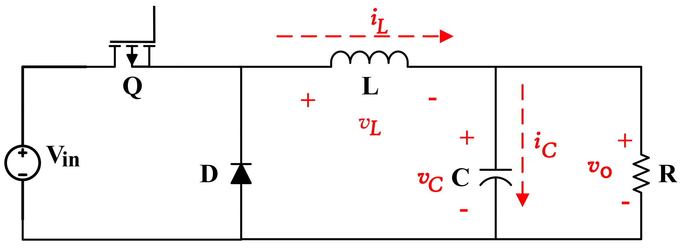
2.1. Buck Power Converter

The ideal buck converter is given in Figure 1, which represents a model of a simple DC–DC power converter. The buck topology consists of a MOSFET (Q) acting as a switch, a diode (D), a DC input voltage source (V i n ), the LC output filter and the load, which in this case is represented by a resistor (R). The output voltage, v o , can be controlled by means of the MOSFET’s duty cycle.
In this work, a 0.5 duty cycle was considered, along with a switching frequency of 200 kHz. The capacitor and coil were set to C = 220 μ F and L = 22 μ H, respectively, and V i n was set to 10 v. Finally, the resistance was chosen so an output current of 2 A was obtained in the load, i.e., R = 2.5 Ω .

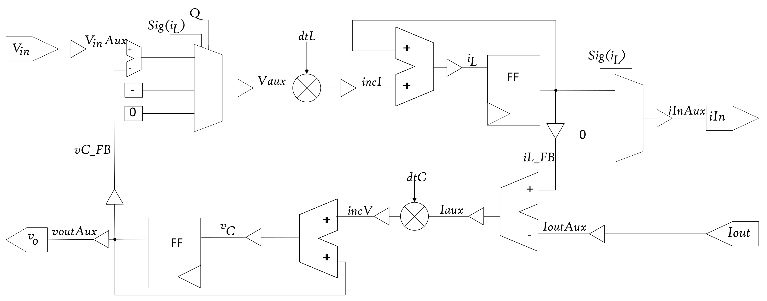
2.2. HIL Model Equations

Buck converters are widely known and have been previously characterized elsewhere with and without losses [2,24,25]. To this end, different discretization methods [26] such as those of Euler [27,28], Tustin [28], zero-order hold (ZOH) [29] or Runge–Kutta [30] have been widely applied to solve the differential equations that determine the model’s behavior. In this work, the forward Euler was chosen to model the mathematical equations that address the behavior of the buck converter due to its simplicity and better synthesis results [1].
The HIL model equations compute the state variables, the voltage in the capacitor ( v C ) and the current through the inductor ( i L ) from previous values by adding an incremental value at each time step [2] according to:
v C ( k + 1 ) = v C ( k ) + Δ t C · ( i L ( k ) G L v o ( k ) )
i L ( k + 1 ) = i L ( k ) + Δ t L · v L ( k )
where k represents the number of integration steps from the beginning of the simulation. Δ t is the simulation time step, G L = 1 / R is the load’s conductance, v L represents the voltage across the coil L (see Figure 1) and v o = v C .
According to the diagram of the buck depicted in Figure 1, v L depends on the switching state of the MOSFET, Q and the direction of i L , so it could be modeled as follows [2]:
v L = V i n v C Q : O N v C Q : O F F & i L > 0 0 Q : O F F & i L = 0

2.3. Numerical Formats

For modeling the architecture of the buck, the mathematical Equations (1)–(3) that describe its behavior were implemented in VHDL-2008. Different NFs could then be considered: real, floating-point and fixed-point NFs.
The real NF consists of a 64-bit floating-point numeric type with double precision, which is not synthesizable [31] but reduces time and complexity in the design process. For this reason, the real type is only considered for simulation purposes as it cannot be implemented into an FPGA. This type is the one considered to describe the buck’s golden HIL model.
The floating-point NF is widely chosen for simplicity. The floating-point NF consists of representing real numbers in the IEEE-754 standard. This NF is synthesizable and can be implemented into hardware; however, the hardware resources needed to simulate the model’s behavior are larger than for fixed-point, resulting in more complex and slower simulations [2,31,32]. Floating-point NFs can be used with their typical formats: single precision, 32-bit, or double precision, 64-bit [31]. Among the 32 bits available for single precision, 1 bit is used for the sign, 8 bits are used for the mantissa and the remaining 23 bits are used for the exponent; while in double precision, from the 64 bits available, 11 are used for the mantissa, 52 bits are used for the exponent and 1 bit is used for the sign. This way, the double precision, 64 bits floating-point NF enables a higher resolution in the fractional part but at the expense of more hardware resources [33].
The fixed-point NF allows the use of smaller and simpler hardware, hence lowering the area and increasing the speed of the model as it reduces the integration time with respect to the floating-point data type [31]. Its main drawback is that a harder effort is required in the design process in order to determine the optimum signal width considering both the integer and the fractional part of every variable in the model [34,35].
When the fixed-point NF is taken into consideration, the designer must focus in using the minimum possible hardware resources, and should select the lengths of the integer and fractional parts of each of the variables in the model in order to be able to fully cover the required numerical range while achieving the minimum possible error with respect to real NFs. To this end, the methodology for selecting the optimum (OPT) widths for the integer and fractional parts of the fixed-point signals and constants is detailed in [34,35], however, the schematic should be previously defined.
The HIL model of the proposed buck converter is depicted in Figure 2. Here, V i n , i I n are the input and output ports corresponding to the input voltage and current, respectively. v o and I o u t represent the output voltage and current in the load, respectively. The selector signal S i g ( i L ) makes reference to the sign of i L , while the selector signal Q depends on the state of the switch. The constants d t C and d t L represent Δ t / C and Δ t / L in Equations (1) and (2), respectively. The signals i n c I and i n c V denote the incremental i L and v C to be added on each integration step, k. Finally, v C _ F B and i L _ F B denote the feedback signals of the state variables at each integration step ( T C L K _ m i n ).
The OPT word-length (WL) and fixed-point format for each of the model’s signals and constants are given in Table 1. The WLs and lengths of the integer and fractional parts of each of them were determined according to the methodology proposed in [34,35]. For example, the integer part of v C should be set to the minimum number of bits that enable representing the maximum value of the signal during the transitory plus 1 extra security bit. The maximum value of v C in the transitory period (see Figure 3) lies below 10 V, then 5 bits would be enough to fully represent the integer part of v C . In contrast, the fractional part width should be selected so as to fully represent the minimum voltage increment with enough numerical resolution, I n c V , during the steady-state period in absolute value. Hence, I n c V 2.5 e 6 , then 19 bits will be needed to fully represent this fractional increment. This leads to an OPT fixed-point signal format of Q5.19 as it can be seen in Table 1. It has to be noted that, in this work, the input and output signals WL were limited by the digital-to-analog converters to a 12-bit standard logic vector.
The proposed NFs allow for the use of different rounding and overflow modes. According to [33], two rounding modes can be found for floating-point NF: round-nearest (default) and round-zero. The mode round-nearest causes the result to be approximated based on the values of discarded bits and the rightmost result bit of the fractional part. Round-zero, or truncate, removes the discarded bits and the rightmost bit remains unchanged. For fixed-point, the same two methods are found for rounding, in this case termed round and truncate, but these perform the same operations as round-nearest or round-zero defined for floating-point NF, respectively. However, for the overflow management in fixed-point NF, two additional modes can be found which were not necessary for floating-point: saturate (default) and wrap. This particularly affects the integer part: in the saturate mode, if the vector is to be truncated in the left and the operand value is out of the representable range for the result, the largest representable value or the most negative representable value is returned, while for the wrap mode, the leftmost bits are simply truncated, which may result in a change of sign [33].
In the proposed example, an input voltage ( V i n ) of 10 V is considered and a 2 A output current was set as the design prerequisite, C and L were set to 220 μ F and 22 μ H, respectively, (see Section 2.1).

2.4. Model Evaluation

In order to evaluate the feasibility of the proposed floating- and fixed-point NF, the mean absolute and mean relative errors [35] with respect to a golden model are computed during the simulation according to:
M A E = 1 N i = 1 N S m o d e l ( i ) S g o l d e n ( i )
M R E = 1 N i = 1 N S m o d e l ( i ) S g o l d e n ( i ) T y p . V a l u e
where N denotes the total number of integration steps in the simulation, while S m o d e l and S g o l d e n represent the state variables from the floating- or fixed-point models and the golden model, respectively. The typical value corresponds to the state variable value in the stationary regime, i.e., 5 V for v C and 2 A for i L . The M A E provides information about the order of the error, while the M R E allows for the error’s comparison with respect to different HIL models or different orders of magnitude in terms of input and output.
Regarding hardware necessities, the models are evaluated for area and speed. This evaluation was performed after synthesis and implementation in Vivado 2020.2 over a Zybo Zynq xc7z020clg100-2 FPGA. Vivado provides the number of LUTs, FFs and DSPs that are needed in the FPGA in order to emulate the proposed model.

3. Experiments, Results and Discussion

In this section, the different experiments are presented and the obtained results are given. For the reader’s clarity, the results are also discussed here.
As it was defined in Section 1, the main objective of this work was to evaluate the performance of HIL models in Vivado 2020.2, using VHDL-2008 as descriptor language and its native IEEE libraries for floating and fixed-point NFs. With this purpose, the HIL model of a buck converter was described in Section 2.
The proposed HIL model was simulated in Questa as Vivado has not yet included support for VHDL-2008 with simulation purposes and an external simulator was needed, while for synthesis and implementation, support for the floating- and fixed-point NFs IEEE libraries has recently been included.
First, the reference or golden model [36] was designed considering real NF. The golden model implements the same numerical equations described in (1)–(3) using real NF. As it was previously described in Section 2.3, real signals are represented using a 64-bit WL. Hence, it could be assumed that the golden model does not lack enough resolution and so it could be used to unveil which part of the error is due to this phenomenon. However, real values are not synthesizable [2,19] and the floating- or fixed-point NF should be used instead.
The proposed HIL model was then translated to floating- and fixed-point NFs and the MAE/MRE were computed considering all possible rounding and overflow modes available in the proposed NFs. Different WLs were considered: a 32-bit (Float32) and 64-bit (Float64) floating-point NF, while for the fixed-point NF, apart from the 32-bit (Fixed32) and 64-bit (Fixed64), a user-defined optimal (OPT) WL for every signal was also considered. Once the correct behavior of the model was verified in the simulation, the floating- and fixed-point HIL models were synthesized and implemented in Vivado 2020.2. Models were evaluated in terms of area and speed performance.

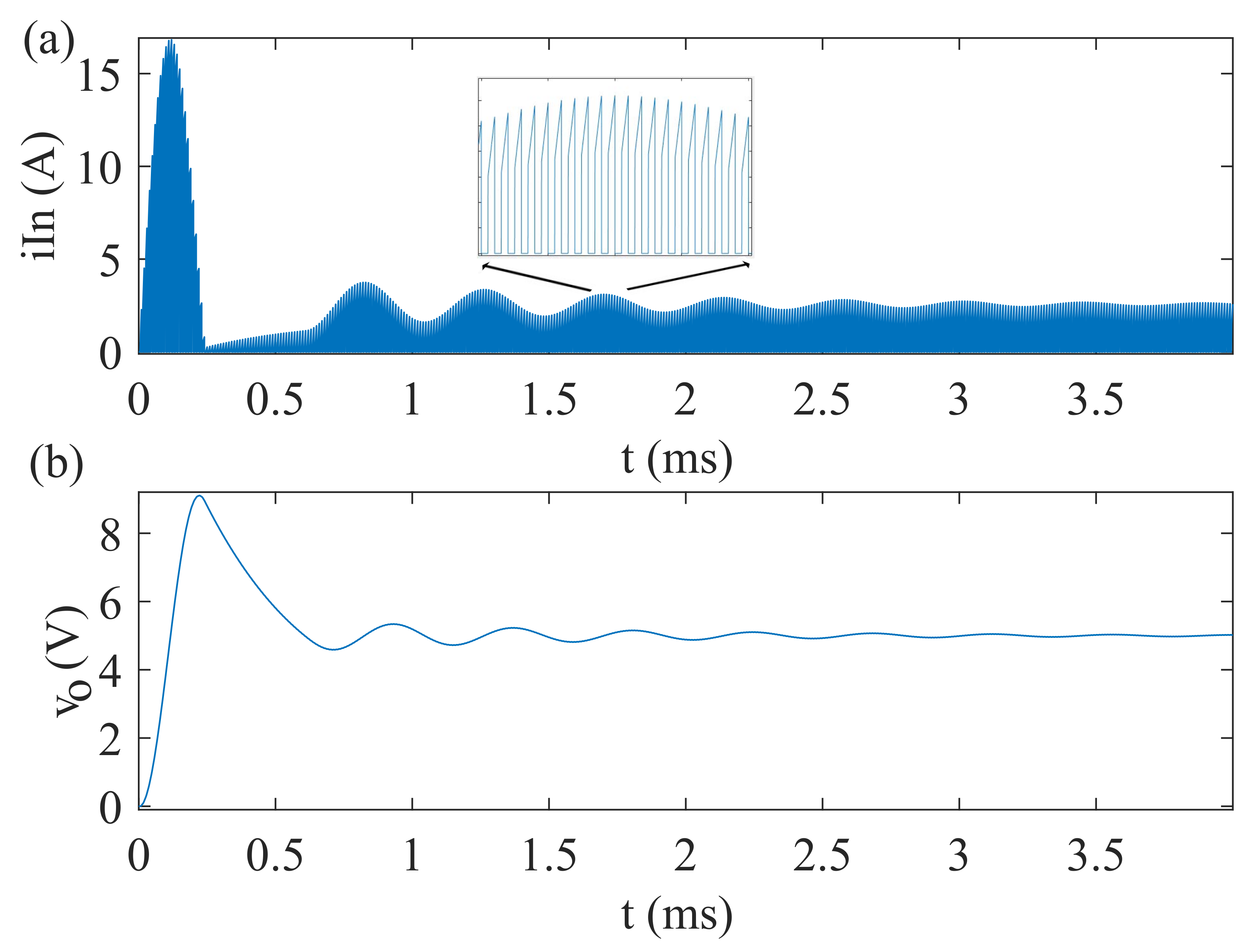
3.1. Buck Converter HIL Model Simulation

Figure 3 depicts the buck converter input current ( i I n ) and output voltage ( v o ), which correspond to the current through the coil, i L when the switch (Q) is on and the voltage in the capacitor, v C . The integration step, d t , was 20 ns for all NFs involved in the HIL model.
The accuracy of the models was evaluated in terms of MAE and MRE against the golden model as in [35], these results are given in Table 2. As it can be observed for any of the possible cases considered, the error is negligible, as for the worst case it is still below 0.5%, similarly to [1,9,35].
Floating-point achieves a lower MRE than fixed-point as even though the WL is the same. The floating-point structure, which consists of the sign, exponent and mantissa, allows for a higher degree of decimal approximation. Nevertheless, the error achieved when using fixed-point notation is low enough to be considered as a good approximation of the golden model.
Regarding rounding and overflow modes, when considering wrapping and truncating for fixed-point or rounding towards zero in floating-point numbers, the MRE is incremented with respect to the default options. Again, this result was expected, but as it can be seen in Table 2, this increase is nearly negligible with respect to the MRE obtained using the default rounding and overflow modes.
Finally, what seems to be a bit surprising is that the MRE obtained when using the optimal (OPT) fixed-point NF along with the wrap and truncate rounding and overflow modes, is lower than when using a 32- or 64-bit length. This result corroborates the idea that the use of a larger WL is not always the best way to reduce numerical errors in HIL models, but knowing which signals and in which part, integer or fractional, more bits are needed in the NF, allows to reduce the MRE while optimizing the synthesis results—as will be seen in subsequent sections.

3.2. Synthesis and Implementation Requirements in Terms of Word Length

This experimental setup was intended to evaluate the hardware needs of the buck converter HIL model in terms of speed and area when different NFs and WLs are considered using the floating- and fixed-point NF IEEE libraries of VHDL-2008 in Vivado 2020.2. For the reader’s clarity, only default rounding and overflow modes were considered in this experiment.
Hardware designers would first consider using a floating-point NF due to its simplicity. Results in terms of speed, minimum integration step (T C L K _ m i n ) and area—the number of DSPs, LUTs and FFs needed—are given in Table 3.
For synthesis and implementation, a Zybo Zynq xc7z020clg100-2 was considered (see Section 2.4) but the Float64 NF needed more hardware resources than those available in that FPGA, so a bigger FPGA of the same family, the Zybo Zynq xc7z020clg200-2 FPGA, was considered for this experiment.
As expected, a larger WL needs a larger area to place the HIL model while turning out to be slower. When no DSPs are involved, the number of LUTs necessary to build the model with Float64 is increased by approximately three times the number of LUTs needed for Float32 NF. Regarding the DSPs, Float64 requires approximately 5 times more units than the Float32 data type. Furthermore, finally, the minimum clock period considering a 64-bit WL turns out to be approximately 30% slower than when the 32-bit WL is considered. Similar results can be found in the literature [32], even though different HIL models were considered. One would expect that replacing LUTs with the DSPs will increase speed, but this is not the case for Float64, as sometimes lowering the number of LUTs required is not enough regarding the decrease in speed or area associated with a DSP (see Table 3).
It is important to notice that, previously, a floating-point NF was not able to be synthesized nor implemented using the IEEE_proposed libraries in Vivado 2020.1. Nonetheless, support has not been fully included for floating-point NFs in Vivado 2020.2 as the function to_fixed() does not present the expected behavior, unless both the fixed and the floating-point operands have the same size, while a normalized size of a 32 or 64-bit WL should be considered.
In contrast to a floating-point NF, a fixed-point NF was synthesizable in Vivado 2020.1 using the IEEE_proposed libraries. Table 4 provides the comparison between the hardware and speed requirements of the buck’s HIL architecture when using both libraries: the IEEE native library of VHDL-2008 and the IEEE_proposed library of VHDL-93. As can be seen, the results obtained when using the native IEEE libraries of VHDL-2008 are very similar to those previously obtained with the same buck’s architecture but using the IEEE_proposed libraries of VHDL-93, even improving them in some cases. These results suggest that the new support included in Vivado 2020.2 reduces the design effort of HIL models as no user-defined libraries are needed, not even for adding external files to the project. Furthermore, in some cases, previous results are even optimized, particularly lowering T C L K _ m i n .
Although the fixed-point NF comprises a harder design process, the overall results are generally improved [2,31,32,35], the speed is increased and the area requirements are lowered, just as happens here. This result is very attractive, however, the MRE is increased (see Table 2). As it can be seen in Table 4, when the minimum number of bits is considered, the T C L K _ m i n is reduced. Nevertheless, the T C L K _ m i n may remain close to the one achieved with a 32-bit WL, and the hardware area needed is drastically reduced. This is particularly noticeable when no DSPs are involved, as both the number of LUTs and FFs needed are lowered to a third with respect to Fixed32 and by more than 10 times with respect to Fixed64.
These results are similar to the ones that can be found in the literature [2,31,32,35], even though different HIL models were considered, thus indicating that the fixed-point NF is more efficient, as it is able to increase the speed by up to nearly 80% with respect to the floating-point NF (see Table 3), particularly lowering the area as the fixed-point 32bit NF needs 1287 LUTs when no DSPs are involved, while the 32-bit floating-point requires approximately 9675 LUTs. This becomes especially relevant as the complexity of the model to be emulated in real-time increases.

3.3. Synthesis and Implementation Requirements in Terms of the Rounding and Overflow Modes

In the previous subsection, only the default rounding and overflow modes for floating- and fixed-point NFs were considered. As it was mentioned in previous sections, these rounding and overflow modes introduce a lower approximation error (see Section 3.1), but at the expense of increased algorithm complexity. In this point, the round-zero rounding mode was considered for the floating-point NF and wrap and truncate were considered for fixed-point NF rounding and overflow modes. The obtained MAE (see Table 2) could be considered negligible as it will always be below 0.5%.
Table 5 provides the comparison in terms of the hardware resources needed between both rounding modes in floating-point NF. When the round-zero mode is used in floating-point NF, T C L K _ m i n is lowered by approximately 20–25% with respect to the round-nearest algorithm for both WLs considered, while the error introduced in the model represents an increase of 0.02% (see Table 2), similarly to [2]. It is worth noting that in this case, the HIL model of the buck converter fits into the selected FPGA even for the Float64 case, in contrast to what happened when the round-nearest algorithm was considered for a floating-point NF.
Regarding a fixed-point NF, the non-default modes, wrap and truncate were considered for overflow and rounding fixed-point NF modes. Table 6 shows the comparison in terms of hardware requirements, area and speed, with respect to the default modes. Similar results to those found for the floating-point NF when the round-zero algorithm was considered were obtained. When the wrap and truncate modes are selected, the T C L K _ m i n is lowered by between 7 and 14 ns while the area is lowered by approximately 25% when no DSPs are involved.

4. Conclusions

This work presents an exhaustive comparison in terms of MRE, area and speed for a HIL model of a buck converter using the native IEEE libraries for VHDL-2008 in Vivado 2020.2.
The results prove that using an optimized fixed-point NF for the synthesis and implementation of the model lowers the area by approximately 95% and increases the speed by approximately 80% with respect to the floating-point NF when considering the default rounding modes. Regarding the area, the floating-point HIL model required 9675 LUTs and 64 FF when no DSPs were involved while the fixed-point HIL model needed 426 LUTs and 50 FFs. With respect to speed, the integration step needed when dealing with the floating-point NF was 84.719 ns; while when considering the optimal fixed-point NF, it was lowered down to 17.745 ns. In addition, using a wrap and truncate algorithm allows resource optimization by further lowering the hardware needs by approximately 30% and increasing speed with respect to the default options in the fixed-point optimal WL HIL model.
The obtained results for the fixed-point NF are similar to those obtained in Vivado 2020.1 when the IEEE_proposed libraries were used. The novelty found is that the floating-point NF is now synthesizable. The newly included support for the floating and fixed-point NF IEEE libraries of VHDL-2008 in Vivado 2020.2 allows the user to benefit from simpler and more efficient design, synthesis and implementation processes of HIL models. However, this support still lacks some compatibility as during the course of the work, some drawbacks were found. First, Vivado does not include this support in the simulation process, hence, an external simulator such as ModelSim or Questa must be used for this purpose. Furthermore, the conversion functions from the floating-point NF to fixed-point NF do not operate as expected.

Author Contributions

E.M.C.-R.: software, data curation, methodology, validation, investigation, writing—original draft, visualization. M.S.M.-G.: conceptualization, software, methodology, validation, writing—review and editing, supervision. A.S.: software, writing—review and editing, supervision. A.d.C.: conceptualization, software, methodology, validation, writing—review and editing, supervision. All authors have read and agreed to the published version of the manuscript.

Funding

This research received no external funding.

Conflicts of Interest

The authors declare no conflict of interest.

References

  1. Yushkova, M.; Sanchez, A.; de Castro, A. Strategies for choosing an appropriate numerical method for FPGA-based HIL. Int. J. Electr. Power Energy Syst. 2021, 132, 107186. [Google Scholar] [CrossRef]
  2. Zamiri, E.; Sanchez, A.; Yushkova, M.; Martínez-García, M.S.; de Castro, A. Comparison of Different Design Alternatives for Hardware-in-the-Loop of Power Converters. Electronics 2021, 10, 926. [Google Scholar] [CrossRef]
  3. Frivaldsky, M.; Morgos, J.; Prazenica, M.; Takacs, K. System Level Simulation of Microgrid Power Electronic Systems. Electronics 2021, 10, 644. [Google Scholar] [CrossRef]
  4. Saito, K.; Akagi, H. A Power Hardware-in-the-Loop (P-HIL) Test Bench Using Two Modular Multilevel DSCC Converters for a Synchronous Motor Drive. IEEE Trans. Ind. Appl. 2018, 54, 4563–4573. [Google Scholar] [CrossRef]
  5. Shin, D.C.; Lee, D.M. Development of Real-Time Implementation of a Wind Power Generation System with Modular Multilevel Converters for Hardware in the Loop Simulation Using MATLAB/Simulink. Electronics 2020, 9, 606. [Google Scholar] [CrossRef] [Green Version]
  6. Montaño, F.; Ould-Bachir, T.; David, J.P. A Latency-Insensitive Design Approach to Programmable FPGA-Based Real-Time Simulators. Electronics 2020, 9, 1838. [Google Scholar] [CrossRef]
  7. Liu, C.; Bai, H.; Zhuo, S.; Zhang, X.; Ma, R.; Gao, F. Real-Time Simulation of Power Electronic Systems Based on Predictive Behavior. IEEE Trans. Ind. Electron. 2020, 67, 8044–8053. [Google Scholar] [CrossRef]
  8. Liang, T.; Liu, Q.; Dinavahi, V.R. Real-Time Hardware-in-the-Loop Emulation of High-Speed Rail Power System With SiC-Based Energy Conversion. IEEE Access 2020, 8, 122348–122359. [Google Scholar] [CrossRef]
  9. Yushkova, M.; Sanchez, A.; de Castro, A. The Necessity of Resetting Memory in Adams–Bashforth Method for Real-Time Simulation of Switching Converters. IEEE Trans. Power Electron. 2021, 36, 6175–6178. [Google Scholar] [CrossRef]
  10. Lin, N.; Dinavahi, V. Detailed Device-Level Electrothermal Modeling of the Proactive Hybrid HVDC Breaker for Real-Time Hardware-in-the-Loop Simulation of DC Grids. IEEE Trans. Power Electron. 2018, 33, 1118–1134. [Google Scholar] [CrossRef]
  11. Lauss, G.; Strunz, K. Multirate Partitioning Interface for Enhanced Stability of Power Hardware-in-the-Loop Real-Time Simulation. IEEE Trans. Ind. Electron. 2019, 66, 595–605. [Google Scholar] [CrossRef]
  12. Dagbagi, M.; Hemdani, A.; Idkhajine, L.; Naouar, M.W.; Monmasson, E.; Slama-Belkhodja, I. ADC-Based Embedded Real-Time Simulator of a Power Converter Implemented in a Low-Cost FPGA: Application to a Fault-Tolerant Control of a Grid-Connected Voltage-Source Rectifier. IEEE Trans. Ind. Electron. 2016, 63, 1179–1190. [Google Scholar] [CrossRef] [Green Version]
  13. Roshandel Tavana, N.; Dinavahi, V. A General Framework for FPGA-Based Real-Time Emulation of Electrical Machines for HIL Applications. IEEE Trans. Ind. Electron. 2015, 62, 2041–2053. [Google Scholar] [CrossRef]
  14. Sanchez, A.; Todorovich, E.; de Castro, A. Impact of the hardened floating-point cores on HIL technology. Electr. Power Syst. Res. 2018, 165, 53–59. [Google Scholar] [CrossRef]
  15. Iranian, M.E.; Mohseni, M.; Aghili, S.; Parizad, A.; Baghaee, H.R.; Guerrero, J.M. Real-Time FPGA-based HIL Emulator of Power Electronics Controllers using NI PXI for DFIG Studies. IEEE J. Emerg. Sel. Topics Power Electron. 2020. [Google Scholar] [CrossRef]
  16. Lucia, S.; Navarro, D.; Lucia, O.; Zometa, P.; Findeisen, R. Optimized FPGA Implementation of Model Predictive Control for Embedded Systems Using High-Level Synthesis Tool. IEEE Trans. Ind. Inf. 2018, 14, 137–145. [Google Scholar] [CrossRef] [Green Version]
  17. Mylonas, E.; Tzanis, N.; Birbas, M.; Birbas, A. An Automatic Design Framework for Real-Time Power System Simulators Supporting Smart Grid Applications. Electronics 2020, 9, 299. [Google Scholar] [CrossRef] [Green Version]
  18. Kumar, P.; Kumar, V.; Pratap, R. FPGA implementation of an Islanding detection technique for microgrid using periodic maxima of superimposed voltage components. IET Gener. Trans. Distrib. 2020, 14, 1673–1683. [Google Scholar] [CrossRef]
  19. Sanchez, A.; de Castro, A.; Garrido, J. A Comparison of Simulation and Hardware-in-the-Loop Alternatives for Digital Control of Power Converters. IEEE Trans. Ind. Inf. 2012, 8, 491–500. [Google Scholar] [CrossRef]
  20. Ahmad, J.; Pervez, I.; Sarwar, A.; Tariq, M.; Fahad, M.; Chakrabortty, R.K.; Ryan, M.J. Performance Analysis and Hardware-in-the-Loop (HIL) Validation of Single Switch High Voltage Gain DC-DC Converters for MPP Tracking in Solar PV System. IEEE Access 2021, 9, 48811–48830. [Google Scholar] [CrossRef]
  21. Nane, R.; Sima, V.M.; Pilato, C.; Choi, J.; Fort, B.; Canis, A.; Chen, Y.T.; Hsiao, H.; Brown, S.; Ferrandi, F.; et al. A Survey and Evaluation of FPGA High-Level Synthesis Tools. IEEE Trans. Comput.-Aided Des. Integr. Circuits Syst. 2016, 35, 1591–1604. [Google Scholar] [CrossRef] [Green Version]
  22. Oruganti, V.S.R.V.; Sarma Dhanikonda, V.S.S.S.; Godoy Simões, M. Scalable Single-Phase Multi-Functional Inverter for Integration of Rooftop Solar-PV to Low-Voltage Ideal and Weak Utility Grid. Electronics 2019, 8, 302. [Google Scholar] [CrossRef] [Green Version]
  23. Markovska, M.; Taskovski, D.; Kokolanski, Z.; Dimchev, V.; Velkovski, B. Real-Time Implementation of Optimized Power Quality Events Classifier. IEEE Trans. Ind. Appl. 2020. [Google Scholar] [CrossRef]
  24. Hassan, M.A.; Li, E.p.; Li, X.; Li, T.; Duan, C.; Chi, S. Adaptive Passivity-Based Control of dc–dc Buck Power Converter with Constant Power Load in DC Microgrid Systems. IEEE J. Emerg. Sel. Top. Power Electron. 2019, 7, 2029–2040. [Google Scholar] [CrossRef]
  25. Cristri, A.; Iskandar, R. Analysis and Design of Dynamic Buck Converter with Change in Value of Load Impedance. Procedia Eng. 2017, 170, 398–403. [Google Scholar] [CrossRef]
  26. Kowalczuk, Z. Discrete approximation of continuous-time systems: A survey. IEE Proc. F Radar Signal Process. UK 1993, 140, 264. [Google Scholar] [CrossRef]
  27. Xu, F.; Dinavahi, V.; Xu, X. Hybrid analytical model of switched reluctance machine for real-time hardware-in-the-loop simulation. IET Electr. Power Appl. 2017, 11, 1114–1123. [Google Scholar] [CrossRef]
  28. Xin, Z.; Wang, X.; Loh, P.C.; Blaabjerg, F. Realization of Digital Differentiator Using Generalized Integrator For Power Converters. IEEE Trans. Power Electron. 2015, 30, 6520–6523. [Google Scholar] [CrossRef]
  29. Park, Y.; Chong, K.T. The numerical solution of the point kinetics equation using the matrix exponential method. Ann. Nucl. Energy 2013, 55, 42–48. [Google Scholar] [CrossRef]
  30. Chen, B.; Solis, F. Discretizations of nonlinear differential equations using explicit finite order methods. J. Comput. Appl. Math. 1998, 90, 171–183. [Google Scholar] [CrossRef] [Green Version]
  31. Zamiri, E.; Sanchez, A.; de Castro, A.; Martínez-García, M.S. Comparison of Power Converter Models with Losses for Hardware-in-the-Loop Using Different Numerical Formats. Electronics 2019, 8, 1255. [Google Scholar] [CrossRef] [Green Version]
  32. Sanchez, A.; de Castro, A.; Martínez-García, M.S.; Garrido, J. LOCOFloat: A Low-Cost Floating-Point Format for FPGAs.: Application to HIL Simulators. Electronics 2020, 9, 81. [Google Scholar] [CrossRef] [Green Version]
  33. Ashenden, P.J.; Lewis, J. VHDL-2008: Just the New Stuff; The Morgan Kaufmann Series in Systems on Silicon; Elsevier/Morgan Kaufmann: Amsterdam, The Netherlands; Boston, FL, USA, 2008. [Google Scholar]
  34. Martínez García, M.S.; de Castro, A.; Sanchez, A.; Garrido, J. Analysis of Resolution in Feedback Signals for Hardware-in-the-Loop Models of Power Converters. Electronics 2019, 8, 1527. [Google Scholar] [CrossRef] [Green Version]
  35. Martínez García, M.S.; de Castro, A.; Sanchez, A.; Garrido, J. Word length selection method for HIL power converter models. Int. J. Electr. Power Energy Syst. 2021, 129, 106721. [Google Scholar] [CrossRef]
  36. Goni, O.; Sanchez, A.; Todorovich, E.; de Castro, A. Resolution Analysis of Switching Converter Models for Hardware-in-the-Loop. IEEE Trans. Ind. Inf. 2014, 10, 1162–1170. [Google Scholar] [CrossRef]
Figure 1. Ideal DC–DC buck converter topology.
Electronics 10 01952 g001
Figure 2. HIL model architecture of the buck power converter for its implementation in VHDL-2008.
Electronics 10 01952 g002
Figure 3. (a) Input current, i I n , ( i L when Q: ’ON’); and (b) output voltage, v o , ( v C ) for the golden HIL model of the proposed buck converter.
Electronics 10 01952 g003
Table 1. Optimal fixed-point NF and word lengths for each of the signals involved in the buck’s HIL model (see Figure 2 according to the methodology described [34,35]).
SignalOPTWL
i L Q6.1825
v C Q5.1925
d t C Q-13.2412
d t L Q-10.2112
I n c I Q-4.1815
I n c V Q-6.1914
I a u x Q6.815
V a u x Q5.612
V i n A u x Q5.612
i I n A u x Q6.512
v o u t A u x Q5.612
I o u t A u x Q3.812
v C _ F B Q5.612
i L _ F B Q6.815
Table 2. Mean absolute (MAE) and relative error (MRE) in the state variable i L and v C for the different numerical formats (NFs), word lengths (WLs) and rounding and overflow modes.
NFWLRound and Overflow
Modes
MAEMRE
v C i L v C i L
Fixed32Round, Saturate0.00400.00390.00080.0020
32Wrap, Truncate0.00770.00930.00150.0047
64Round, Saturate0.00400.00390.00080.0020
64Wrap, Truncate0.00770.00940.00150.0047
OPTRound, Saturate0.00470.00420.00090.0025
OPTWrap, Truncate0.00410.00490.00080.0021
Float32Round nearest0.00020.00010.00000.0000
32Round zero0.00110.00140.00050.0007
64Round nearest0.00020.00010.00000.0000
64Round zero0.00050.00050.00010.0002
Table 3. Hardware needs in terms of speed (T C L K _ m i n ) and area (LUTs and FFs) with and wihtout DSPs, when floating-point NF is considered with different WLs and default rounding modes in VHDL-2008.
ParameterFloat32Float64
T CLK _ min (ns)83.35684.719124.612116.746
DSP40180
LUT8683967520,37824,296
FF6464128128
Table 4. Hardware needs in terms of speed (T C L K _ m i n ) and area (LUTs and FFs) with and without DSPs, considering the fixed-point NF with different WLs and default rounding modes in VHDL-2008.
IEEE Libraries of VHDL-2008
ParameterFixed OPTFixed32Fixed64
T C L K _ m i n (ns)16.88017.74516.94020.58731.67434.800
DSP2060320
LUT242426368128712255925
FF50506464128128
IEEE_Proposed Libraries of VHDL-93
ParameterFixed OPTFixed32Fixed64
T C L K _ m i n (ns)17.60217.74517.40520.70132.74334.873
DSP2060320
LUT241426370129312165928
FF50506464128128
Table 5. Hardware needs in terms of speed (T C L K _ m i n ) and area (LUTs and FFs) with and wihtout DSPs, for different WLs and rounding modes when the floating-point NF is used in VHDL-2008.
Round-Nearest
ParameterFloat32Float64
T C L K _ m i n (ns)83.35684.719124.612116.746
DSP40180
LUT8683967520,37824,296
FF6464128128
Round-Zero
ParameterFloat32Float64
T C L K _ m i n (ns)62.56469.21784.09397.730
DSP40180
LUT4185478211,75414,850
FF6464128128
Table 6. Hardware needs in terms of speed (T C L K _ m i n ) and area (LUTs and FFs) with and without DSPs, for different WLs, as rounding and overflow modes when the fixed-point NF is used in VHDL-2008.
Round and Saturate
ParameterFixed OPTFixed32Fixed64
T C L K _ m i n (ns)16.88017.74516.94020.58731.67434.800
DSP2060320
LUT242426368128712255925
FF50506464128128
Truncate and Wrap
ParameterFixed OPTFixed32Fixed64
T C L K _ m i n (ns)8.5588.57610.52513.86316.93320.462
DSP2060320
LUT11431124110837314668
FF50506464128128
Publisher’s Note: MDPI stays neutral with regard to jurisdictional claims in published maps and institutional affiliations.

