Article

Experimental Investigation into the Optimum Position of a Ring Reflector for an Axial Virtual Cathode Oscillator

Department of Electrical Engineering, Hanyang University, Seoul 04763, Korea
*
Author to whom correspondence should be addressed.
Electronics 2021, 10(16), 1878; https://doi.org/10.3390/electronics10161878
Submission received: 30 June 2021 / Revised: 23 July 2021 / Accepted: 3 August 2021 / Published: 5 August 2021

Abstract

:
A ring reflector was experimentally investigated using an axial virtual cathode oscillator (vircator). The ring reflector was installed behind the mesh anode of the axial vircator to enhance the microwave power output by forming a resonant cavity and increasing the electron beam to microwave energy conversion efficiency. The optimum position of the ring reflector is analyzed through simulations and experiments by varying the anode to reflector distance from 6 mm to 24 mm in 3 mm steps. PIC simulations show that the ring reflector enhances the microwave power of the axial vircator up to 220%. Experiments show that the microwave power from the axial vircator without the ring reflector is 11.22 MW. The maximum average peak microwave power of the axial vircator with the ring reflector is 25.82 MW when the anode to ring reflector distance is 18 mm. From the simulations and experiments, it can be seen that the ring reflector yields decaying enhancement that is inversely proportional to the anode to ring reflector distance and there is no noticeable microwave enhancement after 24 mm. The frequency range attained from the simulations and experiments is 5.8 to 6.7 GHz and 5.16 to 5.8 GHz, respectively. The difference between the simulation and experimental results is due to the error in the anode to cathode gap distance. Although the frequency is slightly changed, the ring reflector seems to have no influence on the frequency of the generated microwave.

1. Introduction

As high-power microwave (HPM) devices have shown potential in various industries, many high-power electron devices have been studied and developed in many applications [1]. The HPM system utilizes pulsed power technologies and electron devices to generate microwaves from a few MW to a few GW. The HPM system is composed of a prime power source, a pulsed power system, and an HPM source. The virtual cathode oscillator (vircator) is one of the high-power electron devices used for the HPM source [2]. The vircator has low intrinsic impedance and is suitable for being driven using a low-impedance pulsed power source [3,4,5,6]. The vircator has two microwave-generating mechanisms. One is the reciprocating motion of electrons between the real cathode and the virtual cathode formed behind the anode, and the other is an oscillation of the virtual cathode. The vircator has been studied widely due to its structural simplicity and its ability to be tuned easily. The structural simplicity allows for high-voltage operation and the tuning characteristics allows for simple frequency modulation. However, the vircator has relatively low efficiency (typically below 5%) compared to other high-power electron devices. Many researchers have studied various types of vircators such as axial vircators, reflex triode vircators, and coaxial vircators to modulate the output microwave and increase its efficiency [7,8,9,10,11,12,13,14].
Researchers installed reflectors in the vircator to improve its efficiency and enhance its output power. Various types of reflectors were studied using particle-in-cell (PIC) simulations and experiments [15,16,17,18,19,20]. Among these reflectors, a ring-type reflector is reported to increase the electron beam to microwave power conversion efficiency by forming a resonant cavity when used in the coaxial vircator [15].
In this paper, an axial vircator with and without a ring-type reflector is experimentally investigated. The microwave power enhancement and the shift in the frequency spectrum due to the installation of the ring reflector have been analyzed through PIC simulations and experiments. A ring reflector is placed behind the mesh anode in the vircator chamber. To find the optimum anode to ring reflector distance, the ring reflector distance is changed from 6 mm to 24 mm in 3 mm steps. The axial vircator is driven using a 10-stage PFN-Marx generator. The influence of the ring reflector is analyzed by looking at the microwave power and the frequency for different anode to ring reflector distances. The overall system description is introduced in Section 2. The simulation and experimental results are analyzed in Section 3 and summarized in Section 4, consequently.

2. System Description

Figure 1 shows the schematic diagram of the experimental vircator system. The experimental system is composed of a pulsed power system, an HPM device, and a measurement system. The pulsed power system compresses the charged voltage and applies the high-voltage pulse to the load. The HPM device generates a high-power microwave using the supplied high-voltage pulse from the pulsed power source. An axial vircator is used as an HPM source in this experiment. As a measurement system, a receiving antenna is installed apart from the high-power microwave device to measure and analyze the characteristics of the pulsed power system and the high-power microwave device.

2.1. PFN-Marx Generator

A 10-stage pulse-forming network (PFN)-Marx generator is selected to drive the HPM device. The PFN-Marx generator is suitable for driving low impedance HPM sources. The PFN consists of a consecutive array of L-C ladder circuit generating rectangular voltage pulses. When the PFNs are erected, the PFN-Marx generator produces a rectangular pulse with the pulse duration of the PFN which is multiplied by the charged voltage on the PFN and the number of stages [21,22,23]. By selecting proper inductance and capacitance values, the impedance of the PFN-Marx generator and that of the axial vircator can be matched without using additional impedance-matching devices, such as a tapered transmission line. The PFNs are constructed using high-voltage capacitors and copper strip inductors. Two PFN arrays with a characteristic impedance of 6 Ω are connected in parallel to reduce the characteristic impedance of the PFN module to 3 Ω. The resulting characteristic impedance of the PFN-Marx generator is 30 Ω. The design parameters of the 10-stage PFN-Marx generator are shown in Table 1. The capacitance and the inductance described in Table 1 is the composite value of two PFN arrays. A schematic circuit of the 10-stage PFN-Marx generator is shown in Figure 2. The circuit shown in Figure 2 is also used in the circuit simulation of the PFN-Marx generator.
Figure 3 shows the typical output waveform of the PFN-Marx generator of the simulations (a) and experiments (b). In the circuit simulation, the PFN-Marx generator is charged with a positive voltage. Alternatively, because the vircator chamber is grounded, the PFN-Marx generator is negatively charged in the experiments. The plateau voltage level of the simulation and experiments is approximately the same. The plateau voltage of −150 kV is used in the PIC simulations.

2.2. Axial Vircator

A vircator is a microwave source classified as a space charge device. It is one of various high-power microwave devices. Among various vircators, the axial vircator extracts the microwave along its axis. The axial vircator used in experiments is housed in a stainless-steel chamber (300 mm in diameter and 400 mm in length). A drift tube (200 mm in diameter) is installed in the chamber to attach the ring reflector and the anode assemblies. The stainless-steel chamber is evacuated to a pressure below 3 × 10⁻⁵ torr using a turbomolecular vacuum pump. The cathode holder and the back plate of the chamber are machined using poly-ether-ether ketone (PEEK) to prevent electrical breakdown between the voltage feeder and the vircator chamber. A stainless-steel mesh anode with geometric transparency of 70% and a graphite cathode are used as the vircator diode. The diameters of the cathode and the mesh anode are 70 mm and 200 mm, respectively. In the experiments, the anode to cathode gap (A-K gap) distance is fixed at 6 mm. The internal structure of the axial vircator is shown in Figure 4.

2.3. Measurement Equipment

To analyze the characteristics of the pulsed power system, the diode voltage and the current are measured using a capacitive voltage divider and a current monitor, respectively. A Pearson coil is used as the current monitor. Both the capacitive voltage divider and the Pearson coil are installed in the voltage feedthrough. The diode voltage and the current are recorded using an oscilloscope (DPO 3054).
To analyze the generated microwave power, a double ridged horn antenna is placed 3 m away from the vircator window. The vircator to antenna distance is selected to accord with the far-field criteria. A planar-doped barrier diode detector (8474B) is used to measure the received microwave power. The diode detector converts microwave power into voltage. The power-voltage conversion ratio of the detector is used in calculating the power from the vircator. The frequency of the microwave power is analyzed using a fast Fourier transform (FFT). The microwave signal and diode detector output are recorded using a high-speed oscilloscope (MSO 71604C). To protect the high-speed oscilloscope and the diode detector, a −30 dB attenuator is installed after the antenna. Considering the attenuation at the RF cable from the antenna to the oscilloscope and the insertion loss at the power divider, the total attenuation at the RF measuring system is −51 dB.
The microwave power at the axial vircator is calculated using Friis’s equation. Friis’s equation is given as:
P r = P r G t G r 4 π D λ 2
Here, Pt is the power at the transmitting antenna, Pr is the power at the receiving antenna, Gt is the transmitting antenna gain, Gr is the receiving antenna gain, D is the distance between the transmitting antenna and the receiving antenna, and λ is the wavelength of the microwave signal [24]. In the RF measuring system, the gain of the transmitting antenna Gt and the gain of the double-ridged horn antenna Gr are 18.5 dBi and 12.82 dBi, respectively.

3. PIC Simulation and Experimental Results

The axial vircator with a ring reflector is investigated through PIC simulations and experiments. The ring reflector with a thickness of 1 mm is installed behind the mesh anode. The outer and inner diameter of the ring reflector is 200 mm and 140 mm, respectively. To optimize the cavity volume formed due to the ring reflector, the simulations and the experiments are conducted by varying the distance between the mesh anode and the reflector from 6 mm to 24 mm in 3 mm steps.

3.1. PIC Simulation

The axial vircator with and without the ring reflector is analyzed before experiments by using an FDTD-PIC simulation (CST particle studio). The simulation region is marked in Figure 4. Because the drift tube is the main operating region, the rest region except the drift tube region is excluded in the simulation model. The diameter and the length of the simulation space are 200 mm and 300 mm, respectively. The surface of the cathode and the anode are placed at z = 20 mm and z = 26 mm, respectively. The threshold voltage for electron emission is set to 100 kV/m. The mesh anode is modeled as a thin sheet with a transparency of 70%. A ramp-shaped voltage pulse with a pulse width of 25 ns and a plateau voltage of −150 kV is used as a vircator operating voltage waveform. Figure 5 shows the phase diagrams of the axial vircator. When the anode to ring reflector distance is between 12 mm and 21 mm, the discontinuous momentum points are distinctly shown around the reflector position. The simulation results showing the microwave power from the axial vircator are depicted in Figure 6. The microwave power is normalized based on that of the axial vircator without the ring reflector. According to the simulations, it can be seen that the ring reflector enhances the microwave power by up to 220%. However, the power enhancement ceased when the anode to ring reflector distance increased to 24 mm. FFT results are shown in Figure 7. The dominant frequencies are around 5.8 GHz when the ring reflector is not used or when the anode to ring reflector distance is larger than 18 mm. However, the dominant frequencies are above 6 GHz when the anode to ring reflector distance is between 6 mm and 15 mm. The reciprocating motion of electrons between the cathode and the virtual cathode is one of the principles of microwave generation in the vircator. According to the simulations, the ring reflector seems to attract the virtual cathode and lengthen the reciprocating distance when the anode to ring reflector distance is between 6 mm and 15 mm. Because the reciprocating frequency is inversely proportional to the reciprocating distance, the frequency shift is caused due to the lengthened reciprocating distance [24].

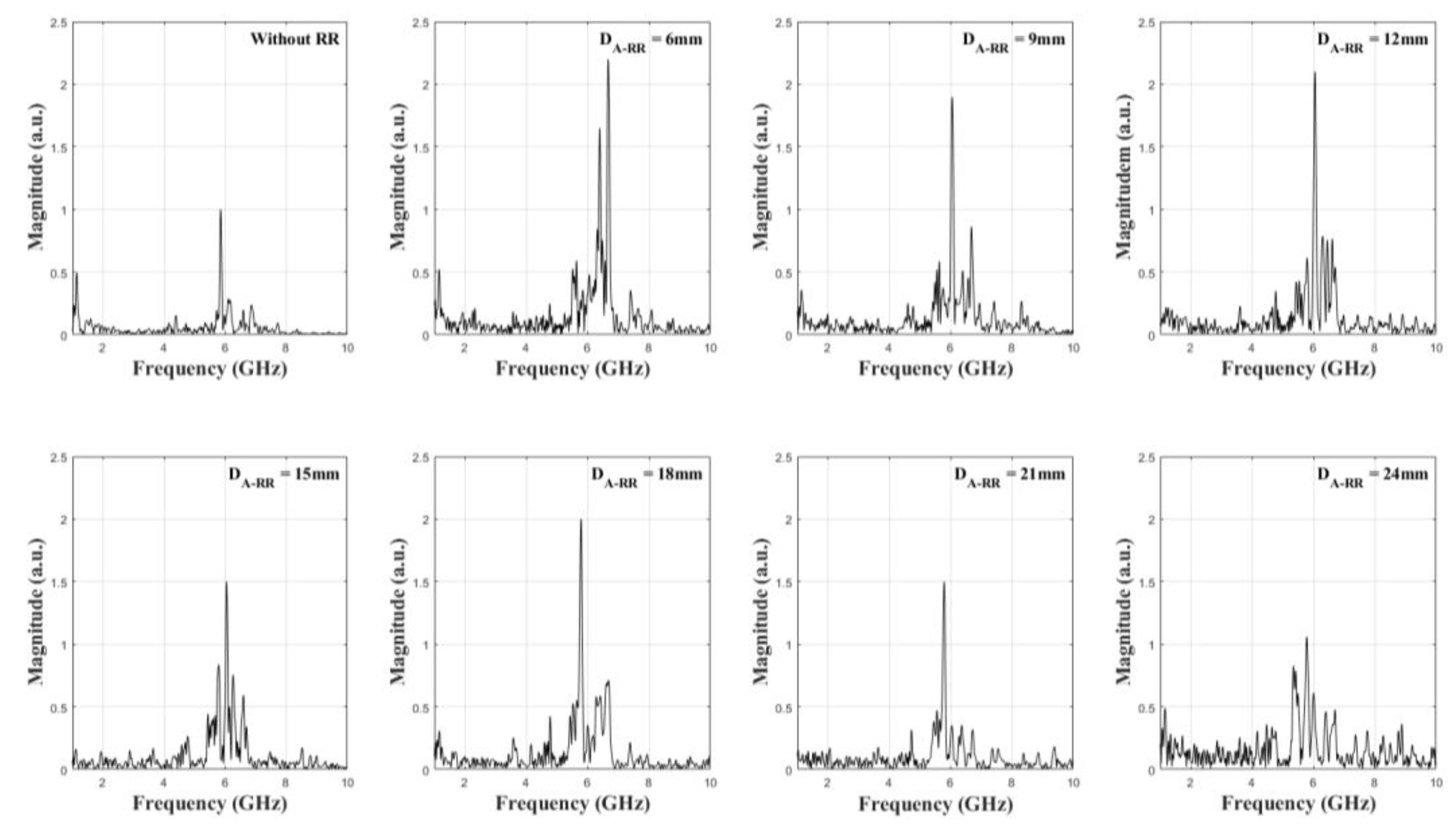
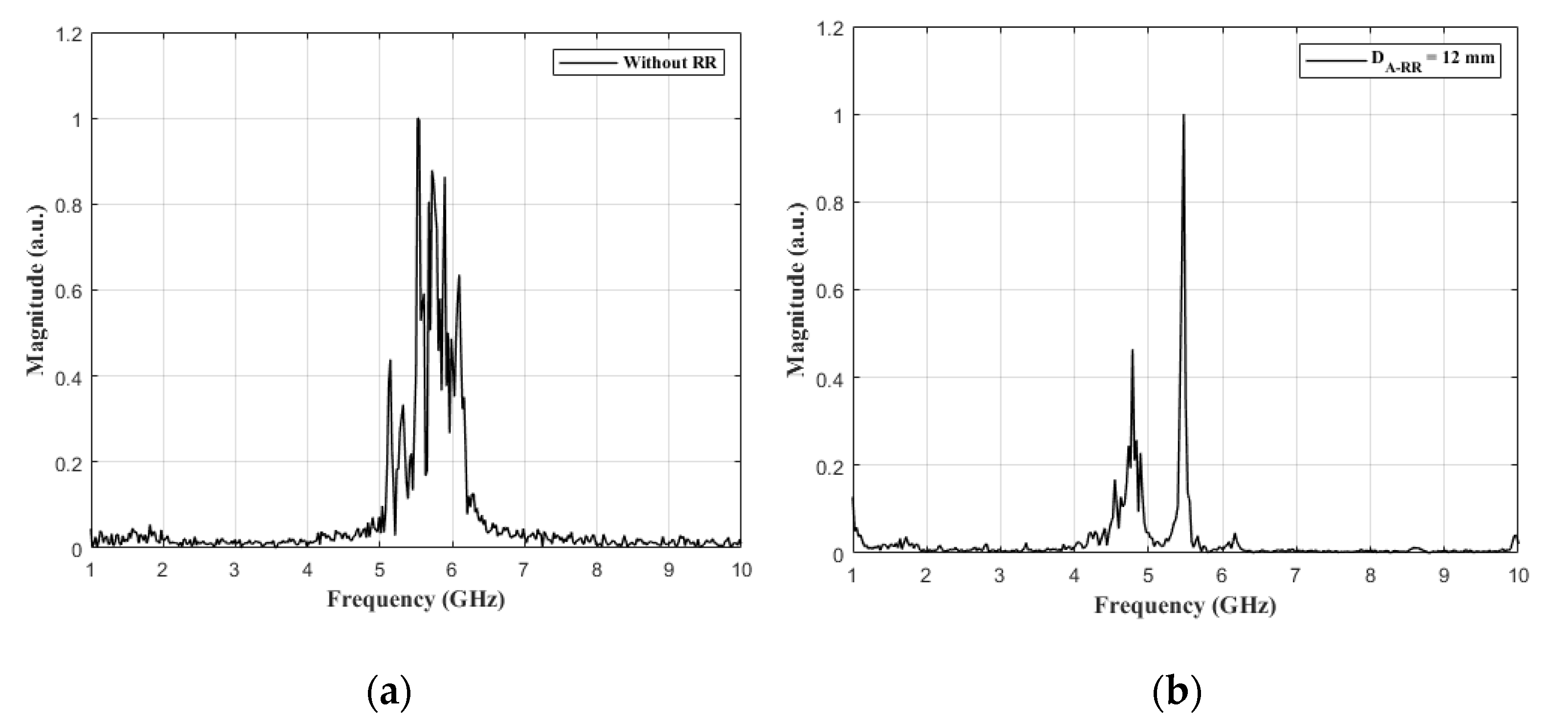
3.2. Experimental Results

The axial vircator is used to investigate and verify the enhancement of the microwave power caused by using the ring reflector. Figure 3b shows the typical voltage and current waveforms when DA-RR is 12 mm. The measured peak and plateau diode voltages were − 196 ± 5 kV and − 150 ± 7 kV, respectively. The rise time and the pulse width of the voltage pulse are 25 ns and 200 ns, respectively. The peak diode current is − 5.6 ± 0.7 kA. According to the experiments, the presence and the position of the ring reflector have no noticeable influence on the diode voltage or the diode current. The output microwave from the axial vircator is calculated using the RF diode detector output voltage and the dominant frequency attained from the FFT results. The typical diode detector output waveforms when the axial vircator is driven without the ring reflector and with the ring reflector (DA-RR is 12 mm) are shown in Figure 8. Although the pulse width of the input voltage is 200 ns, the pulse width of the RF diode detector output is 140 ns. According to the input voltage and the RF detector output waveforms, the microwave is considered to be generated at the plateau part of the input voltage. Figure 9 shows the typical frequency spectra of the measured microwave when the axial vircator is driven without the ring reflector and with the ring reflector (DA-RR is 12 mm). The frequency spectra are obtained from the FFT results of the recorded microwave using the high-speed oscilloscope. The overall experimental results with the ring reflector are shown in Table 2.
The microwave power results are normalized based on the microwave power of the axial vircator without the ring reflector to analyze the tendency of microwave enhancement. The normalized microwave power depending on the anode to ring reflector distance is shown in Figure 10. As shown in the figure, the simulations and experiments show analogous tendencies. From the figure, it can be seen that the microwave power of the axial vircator is significantly enhanced when the anode to ring reflector distance is below 21 mm. Both simulations and experiments show that the decay in microwave power enhancement is inversely proportional to the anode to ring reflector distance, and the ring reflector has no enhancing effects after this distance increases to 24 mm. Figure 11 shows the dominant frequency of the simulations and the experiments versus the anode to ring reflector distance. Simulation results show that the dominant frequency of the axial vircator with and without the ring reflector is formed between 5.8 and 6.7 GHz. According to experiments, the dominant frequency is formed between 5.2 and 5.8 GHz. The vircator frequency is proportional to the root of the input voltage and inversely proportional to the A-K gap distance. Because the plateau voltage of the simulations and experiments is the same, the difference in simulation and experimental frequencies is assumed to be caused by variation in the A-K gap distance. Although this distance can be accurately set to 6 mm in simulations, the A-K gap distance can have small variations during the experiments due to installation errors and the surface conditions of the mesh anode and the cathode. Simulations show that the frequency is slightly shifted upward when the anode to ring reflector distance is between 6 and 15 mm. However, according to the experiments, the ring reflector has no distinguishable frequency shifting tendency. From the figures, it is deduced that the power enhancement and the frequency shift are related to the microwave wavelength. The wavelengths corresponding to the average dominant frequency of the simulations and experiments are approximately 50 mm and 54, respectively. The quarter and half wavelengths of the simulations are 12.5 mm and 25 mm, while the quarter and half wavelengths of the experiments are 13.5 mm and 27 mm. If the microwave power enhancement when the anode to ring reflector distance is set to 18 mm is neglected, it is deduced that the ring reflector has a significant influence on the microwave power and the frequency when the anode to ring reflector distance is below the quarter wavelength, and it has no influence when the anode to ring reflector distance is above the half wavelength.

4. Conclusions

In this paper, the power enhancement and the optimum position of the ring reflector for an axial vircator have been investigated using PIC simulations and experiments. The operation features of the axial vircator with the ring reflector are compared with those of the axial vircator without the ring reflector. The axial vircator is driven using a −150 kV voltage pulse from a 10-stage PFN-Marx generator. The ring reflector is installed behind the mesh anode. The anode to ring reflector distance is adjusted in 3 mm steps from 6 mm to 24 mm. When the axial vircator is driven without the ring reflector, the peak microwave power and the dominant frequencies are 11.22 MW and 5.54 GHz, respectively. Installing the ring reflector enhances the microwave power up to 25.82 MW when the anode to ring reflector distance is 18 mm. According to the simulations and experiments, the available working distance between the anode and the ring reflector is limited to below 24 mm. When the anode to ring reflector distance increases above 24 mm, the power enhancement disappears. The difference between the simulations and the experiments is a frequency shift due to the ring reflector position. According to the simulations, the frequency shift is observed when the anode to ring reflector distance is between 6 and 15 mm. Although the frequency shifts upward when the anode to ring reflector distance is 6 mm, the experiments show no noticeable frequency shift when the anode to ring reflector distance is 12 mm or 15 mm. The changes in frequency and the power enhancement due to the position of the ring reflector are assumed to occur at the quarter and half wavelengths of the generated microwave. In future experiments, we intend to investigate the relation between the position of the ring reflector and the wavelength by varying the frequency of the microwave generated by the axial vircator.

Author Contributions

Conceptualization, S.-H.K. and C.-J.L.; methodology, S.-H.K., C.-J.L. and W.-I.K.; validation, S.-H.K., C.-J.L. and W.-I.K.; formal analysis, S.-H.K., C.-J.L. and W.-I.K.; investigation, S.-H.K., C.-J.L. and W.-I.K.; resources, S.-H.K.; data curation, S.-H.K.; writing—original draft preparation, S.-H.K.; writing—review and editing, K.-C.K. All authors have read and agreed to the published version of the manuscript.

Funding

This research received no external funding.

Conflicts of Interest

The authors declare no conflict of interest.

References

  1. Benford, J.; Swegle, J.A.; Schamiloglu, E. High Power Microwaves, 3rd ed.; CRC Press: Boca Raton, FL, USA, 2015. [Google Scholar]
  2. Jiang, W.; Kristiansen, M. Theory of the virtual cathode oscillator. Phys. Plasmas 2001, 8, 3781–3787. [Google Scholar] [CrossRef]
  3. Chen, Y.; Mankowski, J.; Walter, J.; Kristiansen, M. Cathode and Anode Optimization in a Virtual Cathode Oscillator. IEEE Trans. Dielectr. Electr. Insul. 2007, 14, 1037–1044. [Google Scholar] [CrossRef]
  4. Li, L.; Men, T.; Liu, L.; Wen, J. Dynamics of virtual cathode oscillation analyzed by impedance changes in high-power diodes. J. Appl. Phys. 2007, 102, 123309. [Google Scholar] [CrossRef]
  5. Kovalchuk, B.M.; Polevin, S.D.; Tsygankov, R.V.; Zherlitsyn, A.A. S-Band Coaxial Vircator With Electron Beam Premodulation Based on Compact Linear Transformer Driver. IEEE Trans. Plasma Sci. 2010, 38, 2819–2824. [Google Scholar] [CrossRef]
  6. Roy, A.; Sharma, A.; Sharma, V.; Patel, A.; Chakravarthy, D.P. Frequency Variation of a Reflex-Triode Virtual Cathode Oscillator. IEEE Trans. Plasma Sci. 2013, 41, 238–242. [Google Scholar] [CrossRef]
  7. Guo, L.; Shu, T.; Li, Z.; Ju, J.; Fang, X. Preliminary experimental investigation of an X-Band Cerenkov-type high power microwave oscillator without guiding magnetic field. Rev. Sci. Instrum. 2017, 88, 024708. [Google Scholar]
  8. Neira, E.; Xie, Y.Z.; Vega, F. On the virtual cathode oscillator’s energy optimization. AIP Adv. 2018, 8, 125210. [Google Scholar] [CrossRef] [Green Version]
  9. Mumtaz, S.; Lim, J.S.; Ghimire, B.; Lee, S.W.; Choi, J.J.; Choi, E.H. Enhancing the power of high power microwaves by using zone plate and investigations for the position of virtual cathode inside the drift tube. Phys. Plasmas 2018, 25, 103113. [Google Scholar] [CrossRef]
  10. Parson, J.M.; Lynn, C.F.; Mankowski, J.J.; Kristiansen, M.; Neuber, A.A.; Dickens, J.C. Conditioning of Carbon Fiber Cathodes in UHV-Sealed Tubes at 200 A/cm2. IEEE Trans. Plasma Sci. 2014, 42, 2007–2014. [Google Scholar] [CrossRef]
  11. Parson, J.M.; Lynn, C.F.; Scott, M.C.; Calico, S.E.; Dickens, J.C.; Neuber, A.A.; Mankowski, J.J. A Frequency Stable Vacuum-Sealed Tube High-Power Microwave Vircator Operated at 500 Hz. IEEE Electron Device Lett. 2015, 36, 508–510. [Google Scholar] [CrossRef]
  12. Andersson, J.; Jansson, M.; Aberg, D. Frequency Dependence of the Anod-Cathode Gap Spacing in a Coaxial Vircator System. IEEE Trans. Plasma Sci. 2013, 41, 2758–2762. [Google Scholar] [CrossRef]
  13. Roy, A.; Menon, R.; Mitra, S.; Sharma, A.; Nagesh, K.V.; Chakravarthy, D.P. Influence of Electron-Beam Diode Voltage and Current on Coaxial Vircator. IEEE Trans. Plasma Sci. 2012, 40, 1601–1606. [Google Scholar] [CrossRef]
  14. Turner, G.R. A one-dimentional model illustrating virtual-cathode formation in a novel coaxial virtual-cathode oscillator. Phys. Plasmas 2014, 21, 093104. [Google Scholar] [CrossRef] [Green Version]
  15. Jeon, W.; Sung, K.Y.; Lim, J.E.; Song, K.B.; Seo, Y.; Choi, E.H. A Diode Design Study of the Virtual Cathode Oscillator with a Ring-Type Reflector. IEEE Trans. Plasma Sci. 2005, 33, 2011–2016. [Google Scholar] [CrossRef]
  16. Jeon, W.; Lim, J.E.; Moon, M.W.; Jung, K.B.; Park, W.B.; Shin, H.M.; Seo, Y.; Choi, E.H. Output Characteristics of the High-Power Microwave Generated From a Coaxial Vircator With a Bar Reflector in a Drift Region. IEEE Trans. Plasma Sci. 2006, 34, 937–944. [Google Scholar] [CrossRef]
  17. Gurnevich, E.; Molchanov, P. The Effect of the Electron-Beam Parameter spread on Microwave Generation in a Three-Cavity Axial Vircator. IEEE Trans. Plasma Sci. 2015, 43, 1014–1017. [Google Scholar] [CrossRef] [Green Version]
  18. Baryshevsky, V.; Gurinovich, A.; Gurnevich, E.; Molchanov, P. Experimental Study of an Axial Vircator with Resonant Cavity. IEEE Trans. Plasma Sci. 2015, 43, 3507–3511. [Google Scholar] [CrossRef]
  19. Champeaux, S.; Gouard, P.; Cousin, R.; Larour, J. Improved Design of a Multistage Axial Vircator with Reflectors for Enhanced Performances. IEEE Trans. Plasma Sci. 2016, 44, 31–38. [Google Scholar] [CrossRef]
  20. Baryshevsky, V.; Gurinovich, A.; Gurnevich, E.; Molchanov, P. Experimental Study of a Triode Reflex Geometry Vircator. IEEE Trans. Plasma Sci. 2017, 45, 631–635. [Google Scholar] [CrossRef] [Green Version]
  21. Barnett, D.H.; Rainwater, K.; Dickens, J.C.; Neuber, A.A.; Mankowski, J.J. A Reflex Triode System with Multicavity Adjustment. IEEE Trans. Plasma Sci. 2019, 47, 1472–1476. [Google Scholar] [CrossRef]
  22. Zhang, H.; Shu, T.; Liu, S.; Zhang, Z.; Song, L.; Zhan, H. A Compact Modular 5 GW Pulse PFN-Marx Generatro for Driving HPM Source. Electronics 2021, 10, 545. [Google Scholar] [CrossRef]
  23. Zhang, H.; Yang, J.; Lin, J.; Yang, X. A compact bipolar pulse-forming network-Marx generator based on pulse transformers. Rev. Sci. Instrum. 2013, 84, 114705. [Google Scholar] [CrossRef] [PubMed]
  24. Verma, R.; Shukla, R.; Sharma, S.K.; Banerjee, P.; Das, R.; Deb, P.; Prabaharan, T.; Das, B.; Mishra, E.; Adhikary, B.; et al. Characterization of High Power Microwave Radiation by an Axially Extracted Vircator. IEEE Trans. Electron Devices 2014, 61, 141–146. [Google Scholar] [CrossRef]
Figure 1. Schematic diagram of the experimental system.
Electronics 10 01878 g001
Figure 2. Schematic circuit of the 10-stage PFN-Marx generator.
Electronics 10 01878 g002
Figure 3. Typical output waveforms of the diode voltage and the diode current: (a) simulation results and (b) experimental results.
Electronics 10 01878 g003
Figure 4. Inner structure of the axial vircator.
Electronics 10 01878 g004
Figure 5. Phase space diagram of the axial vircator with and without the ring reflector.
Electronics 10 01878 g005
Figure 6. Normalized microwave power of the axial vircator with and without the ring reflector.
Electronics 10 01878 g006
Figure 7. Frequency spectrum of the axial vircator with and without the ring reflector.
Electronics 10 01878 g007
Figure 8. Typical diode detector output waveform of the axial vircator: (a) without ring reflector and (b) with ring reflector (DA-RR = 12 mm).
Electronics 10 01878 g008
Figure 9. Typical frequency spectrum of the axial vircator: (a) without ring reflector and (b) with ring reflector (DA-RR = 12 mm).
Electronics 10 01878 g009
Figure 10. Normalized microwave power of the simulations and experiments as a function of the anode to ring reflector distance.
Electronics 10 01878 g010
Figure 11. Dominant frequency of the simulations and experiments as a function of the anode to ring reflector distance.
Electronics 10 01878 g011
Table 1. Design parameters of the 10-stage PFN-Marx generator.
ParameterValueParameterValue
Capacitance4.17 nFInductance37.5 nH
PFN stage6Marx stage10
Charging voltage−30 kVErected voltage−300 kV
Pulse width150 nsCharacteristic impedance30 Ω
Table 2. Experimental results.
DA-RRPmin (MW)Pmax (MW)Pavg (MW)Frequency (GHz)
Without RR8.712.311.225.54
6 mm18.112522.795.79
9 mm19.3624.4321.535.59
12 mm15.1422.7520.995.48
15 mm16.2218.6218.285.64
18 mm24.3829.3125.825.48
21 mm12.5316.215.355.16
24 mm11.2213.2712.425.57
Publisher’s Note: MDPI stays neutral with regard to jurisdictional claims in published maps and institutional affiliations.

