Abstract
A novel, improved equivalent circuit model of double-sided linear induction motors (DLIMs) is proposed, which takes the skin effect and the nonzero leakage reactance of the secondary, longitudinal, and transverse end effects into consideration. Firstly, the traditional equivalent circuit with longitudinal and transverse end effects are briefly reviewed. Additionally, the correction coefficients for longitudinal and transverse end effects derived by one-dimensional analysis models are given. Secondly, correction factors for skin effect, which reflects the inhomogeneous air gap magnetic field vertically, and the secondary leakage reactance are derived by the quasi-two-dimensional analysis model. Then, the proposed equivalent circuit is presented, and the excitation reactance and secondary resistance are modified by the correction coefficients derived from the three analytical models. Finally, a three-dimensional (3D) finite element model is used to verify the proposed equivalent circuit model under varying air gap width and frequency, and the results are also compared with that of the traditional equivalent circuit models. The calculated thrust characteristics by the proposed equivalent circuit and 3D finite element model are experimentally validated under a constant voltage–frequency drive.
1. Introduction
The wide range of velocity and acceleration of the linear induction motor (LIM) avoids the intermediate transmission mechanism of linear motion, which reduces the mechanical losses and stresses and improves the system’s reliability [1]. The LIMs have been utilized widely in industrial applications such as aircraft electromagnetic launch or accelerator systems [2,3], transportation systems [4,5,6], handling systems [7], new microgravity drop tower systems [8], etc.
A typical feature of LIM is that it has an entry end and an exit end in the traveling direction (longitudinal) for the primary or secondary cutoff of the LIM, which produces the longitudinal end effect, which the rotary machine does not have. Another feature of LIMs is that the secondary is invariably wider than the primary core in the transverse direction, resulting in the transverse end effect. In addition, the relatively larger air gap between primary and secondary is often inherent in the construction of a LIM [1]. The unique feature of LIM makes its performance different from that of a rotary induction motor. The finite element method (FEM) [9], numerical analysis method [4], equivalent circuit, and magnetic equivalent circuit [10,11] are the main methods used to analyze and calculate the characteristics of LIMs.
The finite element simulation software is convenient for the optimization design of LIMs [12,13]. The FEM is also convenient for the performance calculation of some special cases of linear motors, such as special primary or secondary structure [14], and primary and secondary relative position, e.g., the secondary sheet is displaced sideways from a symmetrical position [15], etc. For a large size linear induction motor, it is not possible to establish a FEM model of partial pole pairs such as rotary motor and a complete pole pairs model of LIM means that it takes longer calculation time and computer resources [16].
The analytical method is another method to solve the performance of a LIM. The one-dimensional (1D) analytical method is the most used. In order to consider the performance and parameters of a LIM more comprehensively, two-dimensional (2D) and three-dimensional (3D) fields are also used to solve the magnetic field and thrust [17,18,19]. It shows that the theoretical results agree very well with the experimental ones, and the 2D solution agrees very well with the rigid 3D solution. The analytical solution of the LIM is helpful to clearly understand the spatial distribution of the electromagnetic field, but it cannot directly reflect the impedance parameters of the motor.
The analysis of electromagnetic fields in the air gap shows that the end effect has a great influence on the operating characteristics of the LIM. The end effect is usually determined by boundary conditions in analytical solution, while the end effect is reflected by modifying the motor impedance parameters in the equivalent circuit of a LIM. In [20], a fast and accurate d–q axis-equivalent circuit model of LIM for drive system simulations was developed based on nonlinear transient finite element analysis. Duncan’s equivalent circuit model is widely utilized in the analysis of characteristics of single-sided linear induction motors (SLIMs) [21,22,23], which provided a practical way to estimate the characteristics of SLIMs. The field-theory-based T-type equivalent circuit is another commonly used model [11,24,25,26,27]. In [24,25], a novel equivalent circuit is presented, and an equivalent circuit considering the asymmetric secondary sheet is developed in [11]. Although the equivalent circuit of SLIM has been widely studied, the equivalent circuit of two kinds of motors is different due to the different structures between SLIM and DLIM—the secondary of SLIM has back iron, while the secondary of DLIM is usually a metal conductive plate. The research on the equivalent circuit of DLIM is not as extensive as that of SLIM because of its limited application. In the traditional equivalent circuit of DLIM, the secondary leakage reactance is usually considered to be negligible, the longitudinal and transverse end effect on the performance of DLIM is demonstrated by coefficients corrected secondary resistance and excitation reactance [26,28]. In the high-speed applications of DLIM, the equivalent circuit only with the longitudinal end effect may be enough to analyze the operating characteristics accurately, while the transverse end effect is neglected [26,27]. Nevertheless, for the large air gap DLIM with low speed, the secondary leakage reactance may not be negligible as high-speed DLIM, and it has a large ratio to the secondary resistance. The inhomogeneous distribution of the air gap magnetic field in the vertical direction will significantly affect the excitation reactance and secondary resistance parameters in the equivalent circuit. In the equivalent circuit model above, few papers take the vertical distribution of the air gap magnetic field into the impedance parameters of the equivalent circuit.
In this paper, an improved equivalent circuit model of DLIMs is developed, which takes the skin effect, the nonzero leakage reactance of the secondary, longitudinal, and transverse end effects into consideration independently, based on the three independent directions model of DLIMs, i.e., longitudinal, transverse and vertical. The paper is organized as follows. In Section 2, the traditional equivalent circuit with longitudinal end effect and the transverse end effect is briefly reviewed. Additionally, correction factors for longitudinal and transverse end effects derived by the 1D analysis models are presented, i.e., longitudinal and transversal models. Then, the new correction factors of the transverse end effect are given [29]. In Section 3, the quasi-two-dimensional (quasi-2D) analysis model is established, and the correction coefficients for skin effect, which considers the inhomogeneous air gap magnetic field vertically, and the secondary leakage reactance are derived. The improved equivalent circuit is proposed, in which skin effect, secondary leakage reactance, longitudinal end effect, and transverse end effect are considered. In Section 4, FEM 3D is used to compare the calculation results in order to verify the proposed equivalent circuit model under different mechanical air gap widths and power frequencies. The FEM results are also compared with the traditional equivalent circuit models. Additionally, variations of forces under negative sequence braking and motoring operations are presented under a constant voltage–frequency inverter; the calculated forces by the proposed equivalent circuit and FEM 3D are experimentally validated. The conclusions of the paper are summarized in Section 5.
2. Traditional Equivalent Circuit Model of DLIM
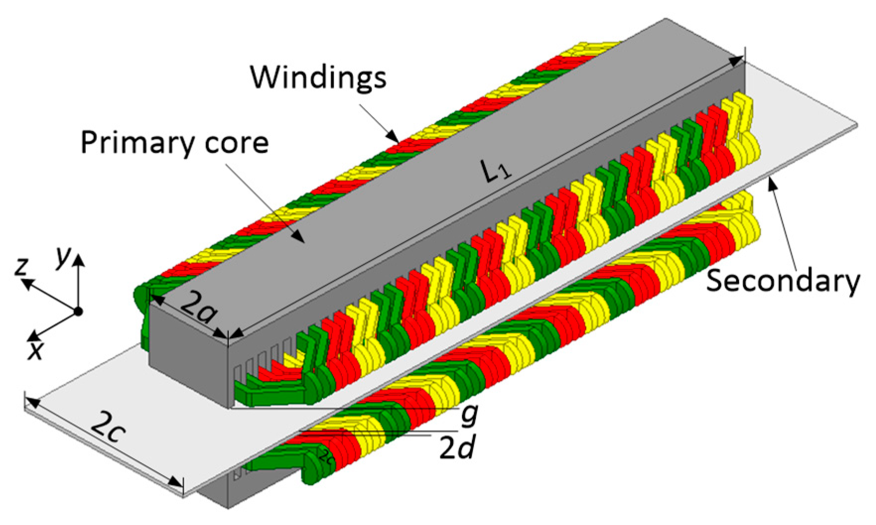
A model was developed in 3D of the linear induction motor and is presented in Figure 1. The direction of the X-axis is longitudinal and is the direction of the secondary (or primary) moving and magnetic-field-traveling wave; vertical moves along the normal line of the secondary surface (Y-axis), and transverse moves along the primary slots (Z-axis). In the field of analytical theories, the 1D method is a practical way to solve the characteristics of DLIMs. The longitudinal and transverse end effects can be considered to act independently or be neglected. The longitudinal and transversal 1D analysis models are shown in Figure 2, where L1 is the length of primary, 2d is the thickness of secondary, g is the mechanical air gap width, τ is the pole pitch, 2a is the width of the primary core, and 2c is the width of secondary.

Figure 1.
Structure of DLIM.
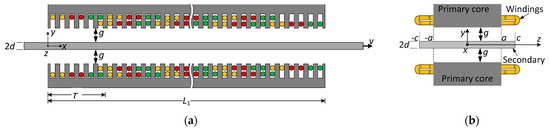
Figure 2.
Analytical model of DLIM: (a) longitudinal model in the XOY plane; (b) transverse model in the YOZ plane.
2.1. Longitudinal Analytical Model of DLIMs
In order to simplify the derivation of the equivalent circuit considering the longitudinal end effect, the assumptions are presented as [26]. As shown in the longitudinal 1D model in Figure 2a, due to the limit length of the primary core, slots containing only one layer of coils at both ends of the primary are called half-filled slots. Numbers of half-filled slots at two ends of the primary both are βτ·m1·q1, which decided by the primary winding short pitch ε. The length of primary can be obtained by
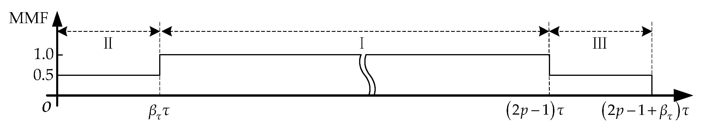
These half-filled slots at two ends of the primary extend about lengths of βτ·τ, and lengths of filled slots are (2p-1-βτ)·τ. The magnetomotive force (MMF) of the primary is presented in Figure 3. Due to only one-layer coil in the half-filled slots, MMF of regions II and III are half of region I, which contains a two-layer coil.
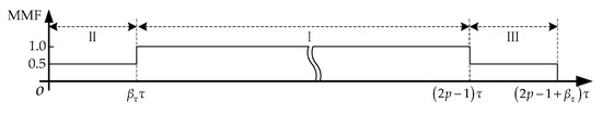
Figure 3.
Longitudinal distribution of MMF.
The current of the primary winding is transformed into an infinitely thin equivalent current density, according to the principle of equal MMF. The expression of primary equivalent current density can be divided into three regions, i.e., the half-filled slots at both ends and full-filled slots, for the existence of half-filled slots at the two ends of the primary core. Additionally, the air gap flux density can then be obtained using Maxwell’s equations. The equivalent circuit parameters, such as secondary resistance and magnetizing reactance, can be obtained using the equal complex power relationship between the magnetic field and the electrical circuit.
The longitudinal end effect coefficients Kr and Kx are denoted as Equations (2) and (3), where Kr is the correction factor of the secondary resistance, and Kx is the correction factor of the magnetizing reactance.
where K1 and K2 are the functions of slip s and goodness factor G. The number of equivalent pole pairs pe is corrected in [11], due to the half-filled slots may affect the precise of the calculation, where p is the actual number of the pole pairs, m1 is the number of primary phases, and q1 is the number of coil sides per phase per pole.
2.2. Transverse Analytical Model of DLIMs
The motor is divided into two independent models—longitudinal and transverse. The longitudinal end effect is neglected when solving the transverse end effect [28]. The correction factors considering the transverse edge effect Cr and Cx are given by
These two coefficients are used to correct the secondary resistance and excitation reactance, respectively. The T in Equations (5) and (6) is obtained by (7) as follows:
where r, λ, α are given as Equations (8)–(10), T is the function of the slip s, goodness factor G, and motor parameters, such as the width of primary core 2a and pole pitch τ, and k = π/τ.
The transverse end effect may be accounted for by introducing a larger (equivalent) primary stack width 2ae instead of 2a, and 2ae = 2a + kg·(2d + 2g), and range of correction coefficient kg is 1.2 to 2 [29]. By introducing the new equivalent stack thickness into Equations (5)–(9), new correction coefficients Cer and Cex of transverse end effect can be obtained.
2.3. Equivalent Circuit of DLIM with Longitudinal and Transverse End Effects
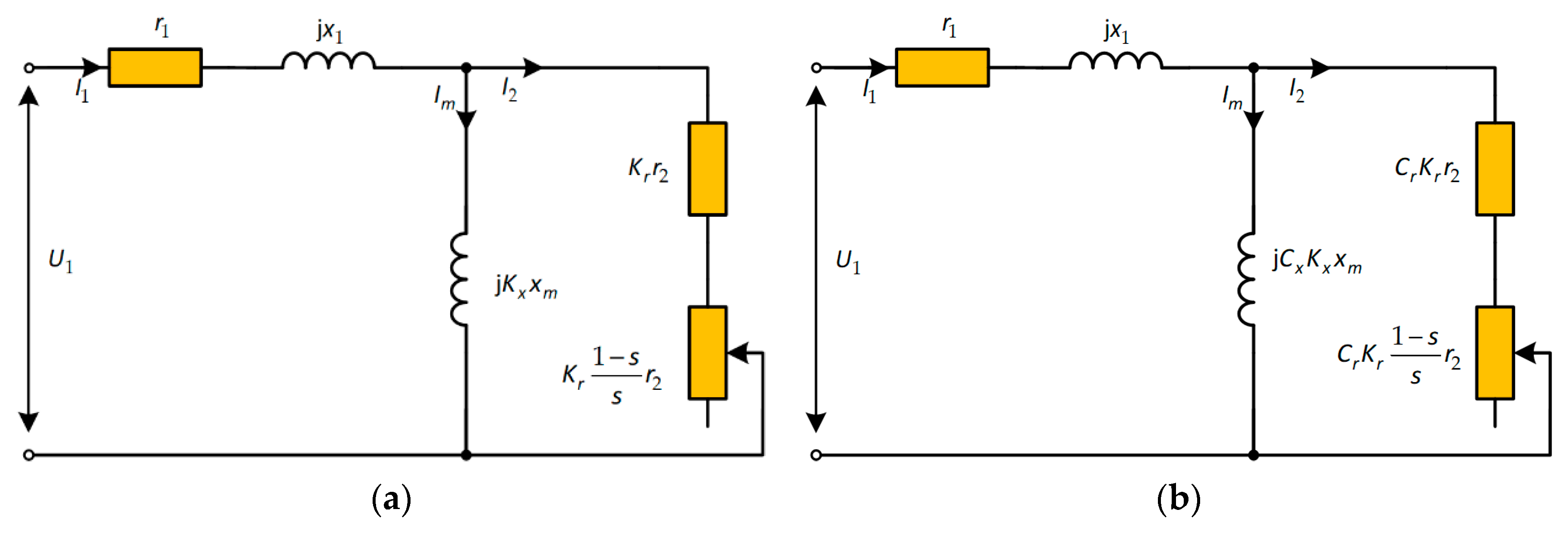
The conventional T-type equivalent circuit with longitudinal and transverse end effects is represented in Figure 4. The parameters in the T-circuit, namely, the primary resistance r1, primary leakage reactance x1, secondary resistance reduced to the primary r2, exciting inductance xm, and secondary leakage reactance x2 are usually considered to be 0 for plate DLIM [26].
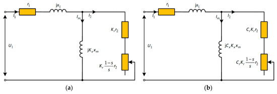
Figure 4.
Equivalent circuit of DLIM: (a) only longitudinal end effect considered (EC-L); (b) both longitudinal and transverse end effect considered (EC-LT).
When coefficients Cer and Cex are used to replace the traditional transverse end effect correction factors Cr and Cx in Figure 4b, a new equivalent circuit (EC-LTe) can be used to calculate the characteristics of a DLIM. When the coefficients Kr, Kx, Cr (Cer), and Cx (Cex) are 1, the longitudinal and transversal end effects are neglected. The equivalent circuit of DLIM is similar to that of rotary induction motor (RIM); therefore, it is convenient to analyze the performance of DLIM as that of RIM based on the equivalent circuit.
3. Proposed Novel Equivalent Circuit Model of DLIMs
Based on the traditional equivalent circuit, the proposed model for the large air gap DLIM in this paper also considers the secondary leakage reactance and skin effect and derives correction coefficients for the equivalent circuit impedance by quasi-2D field model, that is, in the quasi-2D field, the influence of the air gap magnetic field variation in the vertical direction on the performance of DLIM is further considered, while the previous longitudinal and transverse analysis models consider that the air gap magnetic field remains unchanged in the vertical direction, as discussed in Section 2.
Since the longitudinal and transverse end effects were taken into account independently in the previous equivalent circuit, they are not considered in the quasi-2D field analysis in this section.
3.1. Vertical Quasi-Two-Dimensional Analytical Model of DLIMs
To simplify the analytical model, the assumptions are as follows [4,11,17]:
- (1)
- The primary core will not be saturated, and the conductivity of the cores is equal to zero;
- (2)
- The primary and secondary are infinitely long in the longitudinal direction and wide enough in the transverse direction;
- (3)
- Primary and secondary currents flow in the z-direction, and primary currents flow in infinitesimally thin sheets.
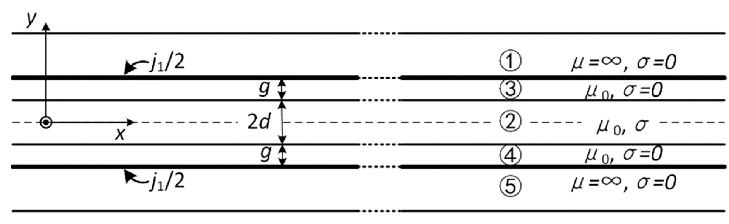
The quasi-2D representation of the DLIM is shown in Figure 5.
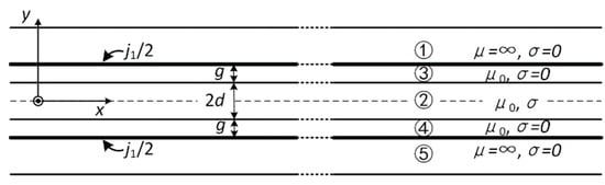
Figure 5.
Quasi-2D analytical model of DLIM.
On the basis of the theory of the linear induction motor and Maxwell’s equations, the magnetic flux density and electric field intensity can be calculated by
For the reason that the current of primary and secondary flow in the z-direction, the vector magnetic potential A can be simplified as
In region 2 (secondary), the following Equation (13) is obtained:
where μ0 is the air magnetic permeability, σ is the conductivity of the secondary, and ω is the angular supply frequency of primary. In regions 3 and 4, the conductivity σ in these regions are 0 for no conductor in this region, and Equation (13) can be simplified as follows:
Solutions of Azi in domains 2 to 4 are given by
where , .
Undetermined constants c1 to c6 in Equation (15) are solved by the satisfactions of the following boundary conditions:
- (1)
- Primary surface (domains 1 and 3; 4 and 5): y = ±ge = ±(d + g);
- (2)
- Secondary surface (domains 2 and 3; 2 and 4): y = ±d;
- (3)
- According to the symmetry distribution of the magnetic field in the air gap,
The electric field intensity in the air gap and the secondary is denoted by the following:
3.2. Parameters Calculation for the Proposed Equivalent Circuit Model
The electromagnetic power transferred from the primary to the air gap and secondary can be calculated by the following equation:
where the Ez3 is the electric field intensity in the air gap, and P23 = P2 + P3, P3 is the active power in the air gap, which is usually considered as 0.
When the slip is 0, the complex power calculated by Equation (20) only has the reactive power Q30 on the exciting reactance. There is no active power and reactive power in the secondary, i.e., P23 = 0 and Q20 = 0, where Q23= Q20+ Q30.
The current of the secondary branch reduced to the primary is 0. Therefore, the excitation reactance with secondary leakage reactance and skin effect considered can be obtained by the following expression:
where Km is the correction coefficient of excitation reactance without end effect.
When the slip is not 0, the power in the air gap and secondary is the power on the excitation reactance, secondary leakage reactance, and secondary resistance and is given by
The primary induced electromotive force (emf) E1 can be calculated by
The reactive power in the air gap is as follows:
The complex power in the secondary can be obtained by the following equation:
The active power P2 and reactive power Q2 in the secondary are
The conjugate current of the secondary branch reduced to the primary is
The active power P2 and reactive power Q2 are the power of secondary resistance and leakage reactance, respectively. Hence, the resistance and the leakage reactance of the secondary sheet can be obtained according to the following Equations (30) and (31). Both the resistance considering skin effect and the leakage reactance of the secondary can be expressed by the secondary resistance without end effect.
From Equations (22) and (30), the correction coefficients of secondary resistance and excitation reactance considering skin effect and secondary leakage reactance are calculated as Equations (32) and (33).
The equations show that these two correction coefficients are closely related to the parameters of the DLIM, e.g., the secondary thickness and the mechanical air gap.
3.3. Proposed Equivalent Circuit Models
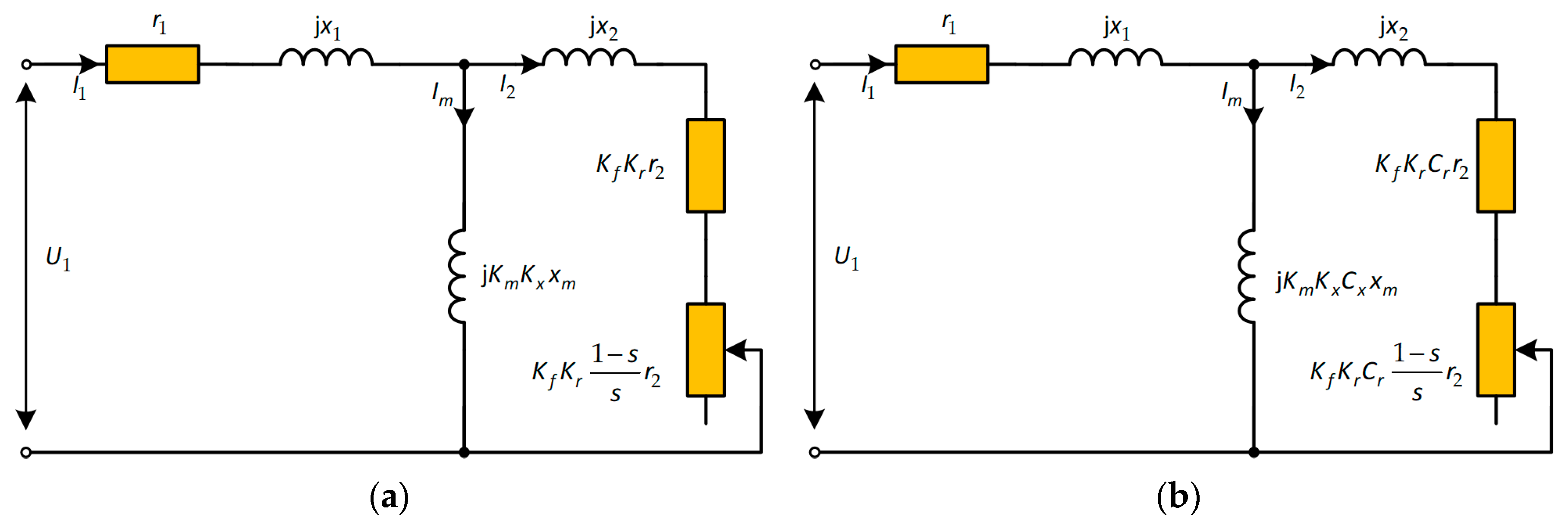
Let the coefficients of transverse end effect be 1, that is, ignore the influence of transverse end effect, add secondary leakage reactance on the secondary branch, and use the correction coefficients of Equations (32) and (33) to modify the secondary resistance and excitation reactance; then, a new T-type equivalent circuit without considering transverse end effect can be obtained, as shown in Figure 6a.
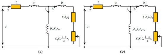
Figure 6.
Novel equivalent circuits of DLIM: (a) with skin effect, secondary leakage reactance, and longitudinal end effect considered (EC-LS); (b) with longitudinal end effect, transverse end effect, and skin effect and secondary leakage reactance considered (EC-LTS).
In the traditional equivalent circuit shown in Figure 4b, the excitation reactance and secondary resistance are modified, respectively, by using the correction coefficients derived in this section, and secondary leakage reactance is added to the secondary branch. An improved equivalent circuit proposed in this paper can be obtained, as shown in Figure 6b. Similarly, if the transverse end effect coefficients Cer and Cex are used to replace the traditional Cr and Cx in Figure 6b, respectively, another new T-type equivalent circuit (EC-LTeS) for solving the motor characteristics is obtained.
In the equivalent circuit of Figure 6b, the correction coefficients of three directions and secondary leakage reactance of the DLIM model are considered. The mechanical power considering all effects is as follows:
4. Experiments and Discussion
4.1. Calculation of Operating Characteristics by Traditional and Improved Models
The results of the 3D finite element model were compared with those of the improved equivalent circuit in order to verify the proposed equivalent circuit model. The results were also compared with the 2D FEM, the traditional equivalent circuit model, which only considers the longitudinal end effect, and the equivalent circuit, which includes the longitudinal and transverse end effects.
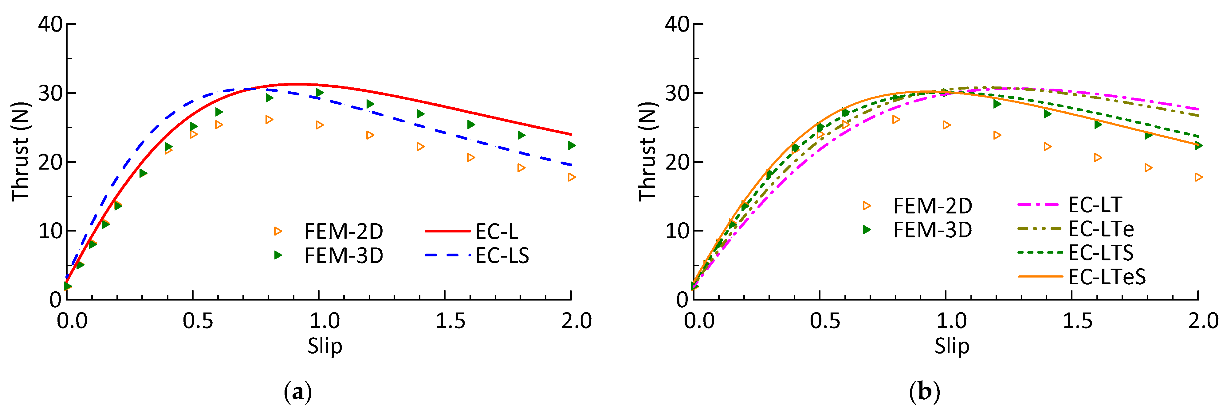
The thrust slip characteristics of different mechanical air gap widths calculated by the equivalent circuits were compared with the results calculated by the FEM 3D and 2D models, as shown in Figure 7, Figure 8 and Figure 9. In the simulations and calculations, the secondary thickness is 3 mm, the current is 6.85 A, and the thickness of the mechanical air gap is 0.0075, 0.0105, 0.0135 m, respectively. The specifications of the DLIM are shown in Table A1.
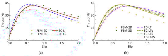
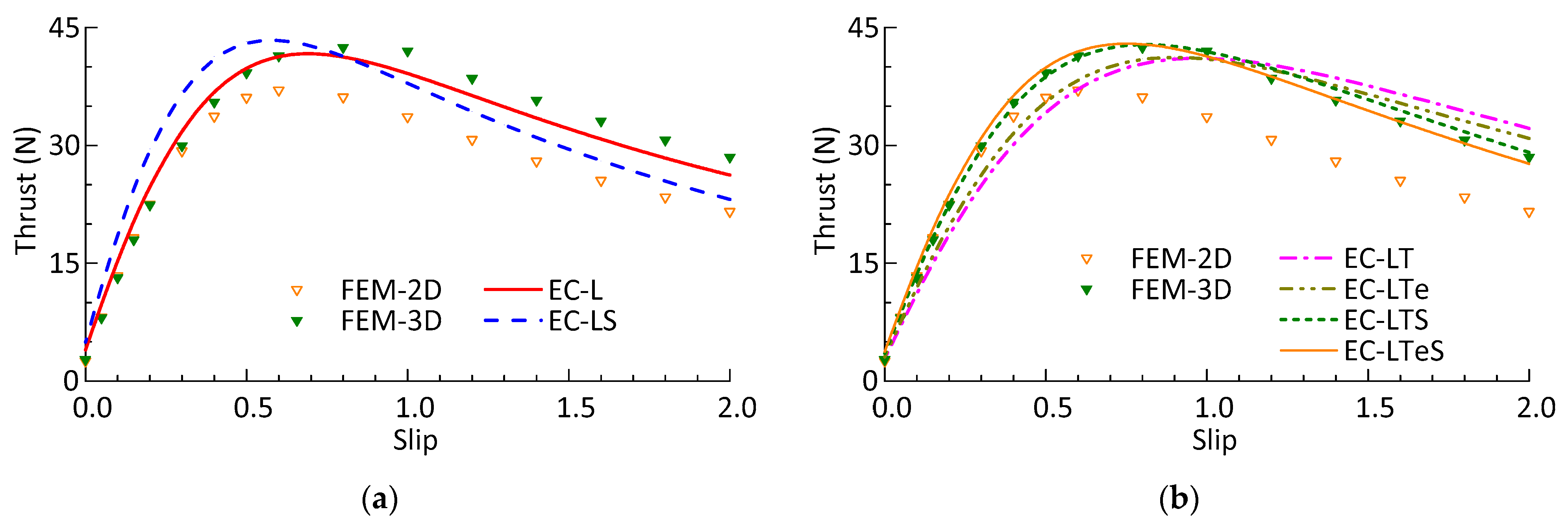
Figure 7.
Thrust versus slip characteristics with a mechanical gap of 0.0075 m: (a) is calculated by equivalent circuit with longitudinal end effect (EC-L), skin effect, the air gap leakage, and longitudinal end effect considered (EC-LS), FEM 2D, and FEM 3D model; (b) is calculated by longitudinal end effect, transverse end effect (EC-LT, EC-LTe), in addition to skin effect and secondary leakage reactance considered (EC-LTS, EC-LTeS), FEM 2D and 3D model.
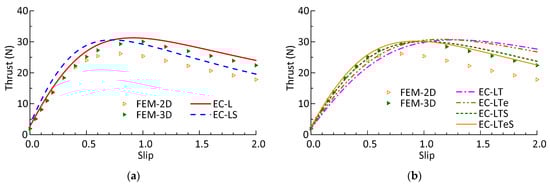
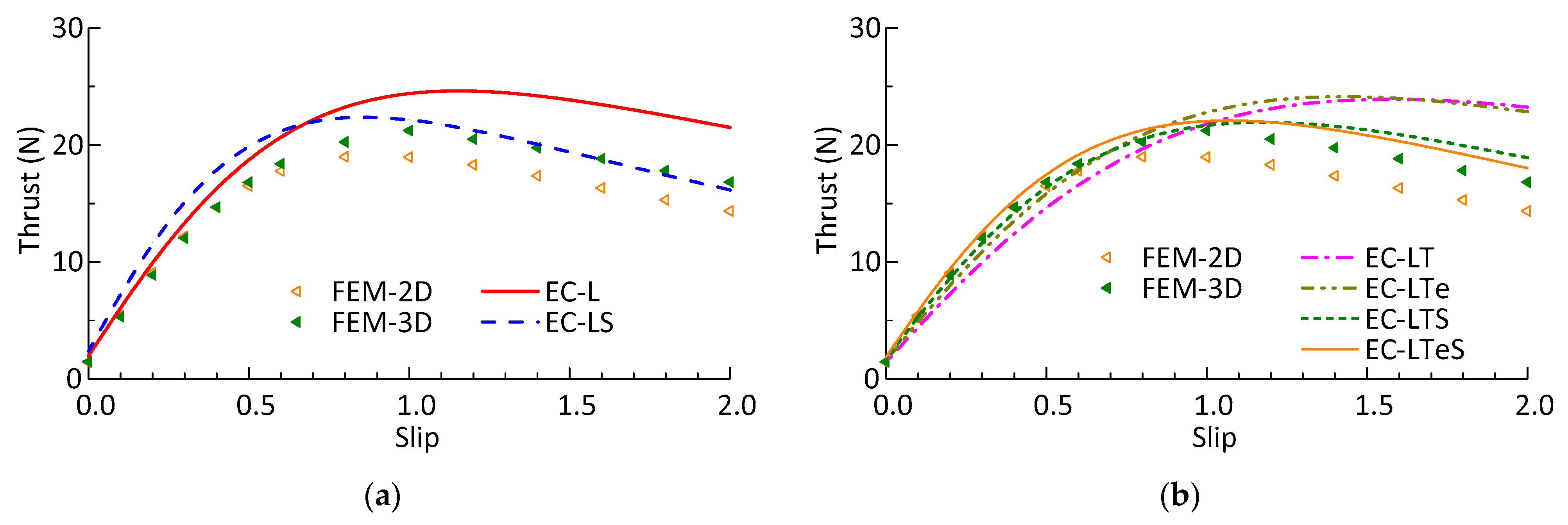
Figure 8.
Thrust versus slip characteristics with a mechanical gap of 0.0105 m: (a) is calculated by equivalent circuit EC-L, EC-LS, FEM 2D, and FEM 3D model; (b) is calculated by equivalent circuit EC-LT, EC-LTe, EC-LTS, EC-LTeS, FEM 2D, and 3D model.
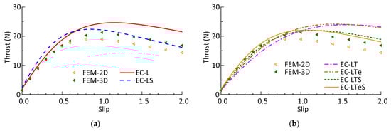
Figure 9.
Thrust versus slip characteristics with a mechanical gap of 0.0135 m: (a) is calculated by equivalent circuit EC-L, EC-LS, FEM 2D, and FEM 3D model; (b) is calculated by equivalent circuit EC-LT, EC-LTe, EC-LTS, EC-LTeS, FEM 2D, and 3D model.
The 2D simulation results are close to the 3D results only in a small slip range, and the difference becomes larger with the increase of slip. In the negative braking region (s > 1), the maximum errors between 3D and 2D calculation results are 24.3%, 20.5%, and 14.8%, respectively, when the mechanical air gap is 0.0075, 0.0105, 0.0135 m.
The thrust calculated by the equivalent circuit, which considers only the longitudinal end effect, the equivalent circuit, which considers longitudinal end effect, the skin effect, and secondary leakage reactance are larger than the 2D simulation results in the slip range, which also cannot accurately reflect the trend of the 3D calculation results with different mechanical air gap widths.
For the DLIM with a large air-gap-to-pole-pitch ratio, the calculated thrust of equivalent circuit considering longitudinal and transverse end effect (EC-LT and EC-LTe) is consistent with 3D simulation values within a certain slip range. In the range of slip, with the increase of air gap width, this kind of equivalent circuit cannot reflect the motor performance well, and the average errors of the motor with the three mechanical air gap widths are 10.7%, 13.63%, and 17.33%, respectively. Even if the new transverse end effect coefficients are used in the equivalent circuit (EC-LTe), the average errors of the thrust are reduced by about 3%.
The results of the proposed equivalent circuit (EC-LTS or EC-LTeS) in the slip range are basically consistent with the results of the FEM 3D. The proposed equivalent circuit can more accurately reflect the thrust characteristics of the large air gap DLIM, compared with other equivalent circuits, as shown in Figure 7, Figure 8 and Figure 9. With the three mechanical air gaps, the average error between the calculated results and the 3D simulation ones are 1.95%, 3.11%, and 5.17%, respectively.
The thrust characteristic curve calculated by the equivalent circuit with new transverse end effect correction coefficients (Cer and Cex) is slightly different from that calculated by the traditional ones (Cr and Cx), whether the traditional equivalent circuit only considers longitudinal and transverse, or the improved equivalent circuit proposed in this paper. The proposed equivalent circuit with the new transverse end effect coefficient has smaller errors in the negative braking region, which are 1.12%, 2.17%, and 7.5%, respectively, compared with the corresponding errors of 3.4%, 5.82%, and 10.37% with traditional ones.
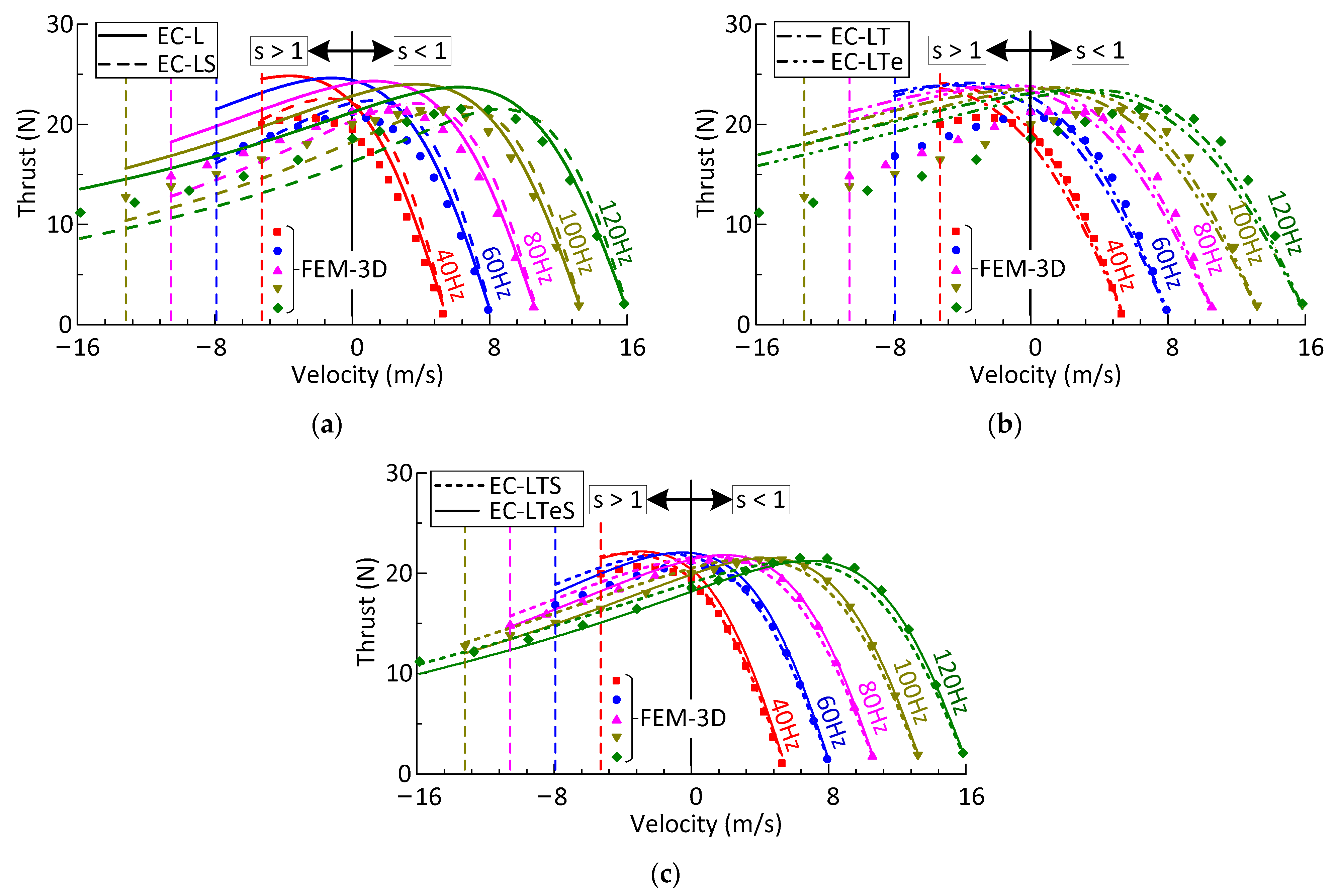
In Figure 10, the calculated thrust obtained by the equivalent circuits are compared with the results of the FEM 3D model. In the simulations and calculations, all the results are a function of the velocity when the mechanical air gap length is 0.0135 m, the current is 6.85 A, frequency is 40, 60, 80, 100, and 120 Hz.
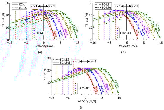
Figure 10.
Thrust versus velocity characteristics at constant current calculated by FEM 3D model: (a) equivalent circuit EC-L and EC-LS model; (b) equivalent circuit EC-LT and EC-LTe model; (c) equivalent circuit EC-LTS and EC-LTeS model.
The calculated thrust of the equivalent circuit considering only the longitudinal end effect (EC-L) is larger than that of FEM 3D because the transverse end effect, the vertical variation of air gap magnetic field, and the secondary leakage reactance are neglected. In the negative braking region, the calculated results by the equivalent circuit with skin effect and longitudinal end effect (EC-LS) are closer to the 3D simulation ones, compared with EC-L in Figure 10a. However, the minimum average error between the calculated (EC-LS) and the simulated thrust in the slip region is still more than 11%.
In Figure 10b, the thrust characteristics of simulation and calculated by two equivalent circuits considering longitudinal and transverse end effects (EC-LT and EC-LTe) are compared. In the motoring region of the synchronous speed side before the maximum FEM 3D value, and the thrust calculated by the equivalent circuit EC-LTe is closer to that of 3D simulation. However, the calculation errors of the two equivalent circuits are more than 12% in the slip range. In the negative braking region, the average errors between the calculation results of these two equivalent circuits and the simulation results are even more than 40%, 35%, respectively; hence, these equivalent circuits cannot accurately reflect the force characteristics of the motor.
Compared with the previous four equivalent circuits, the improved equivalent circuit proposed in this paper can be in good agreement with the FEM 3D calculation values in both the motoring and negative braking region, although there is a slight difference in the thrust velocity characteristic curve by using two different transverse end effect coefficients, as shown in Figure 10c. At low frequency, e.g., 40 Hz, the results calculated by using traditional transverse end effect coefficients are closer to that of simulation, and the average error between the calculated and simulation results is 4.24%, while at higher frequencies, the results calculated by using the new transverse end effect coefficients may be better consistent with the simulation ones, and the average error between the calculated thrust and FEM results is less than 3%.
4.2. Experimental Validation
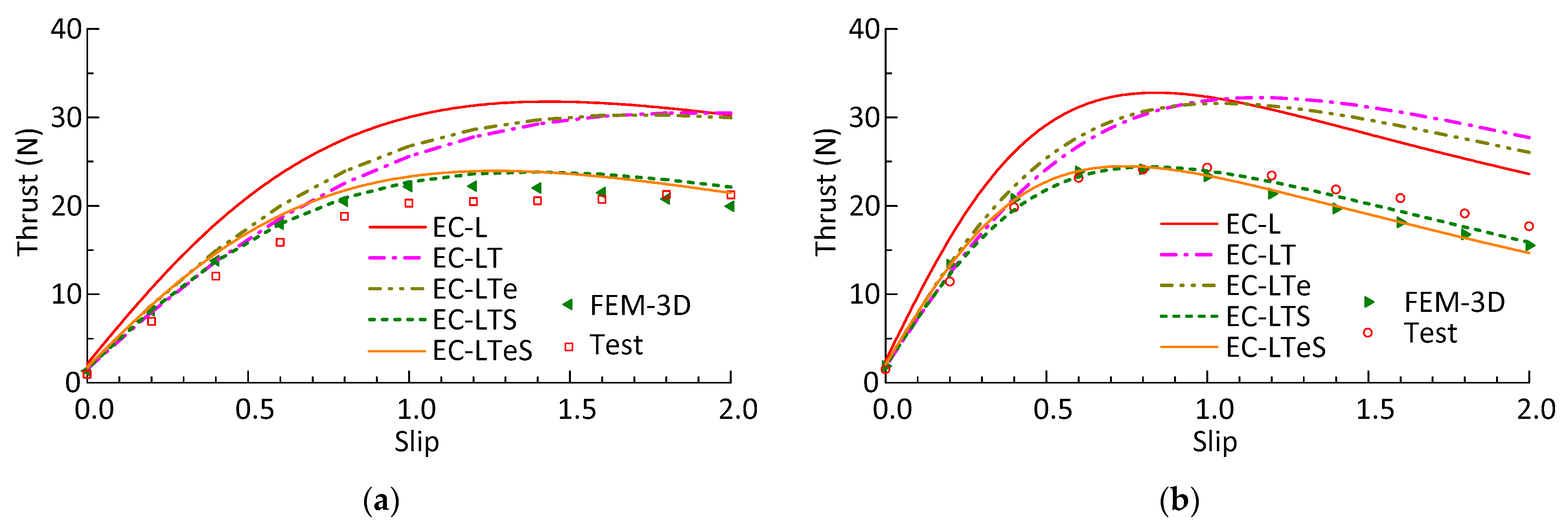
In Figure 11, the analytically calculated thrust versus slip characteristics under a constant voltage–frequency drive is compared with the FEM results and measurements at 60 Hz and 110 Hz, and the mechanical air gap is 0.0135 m. The trend of analyzed results by the proposed equivalent circuit (EC-LTS and EC-LTeS) over the whole slip range is basically in accordance with the measurements and FEM results. Additionally, it presents slight differences in variation of the transverse end effect coefficients.
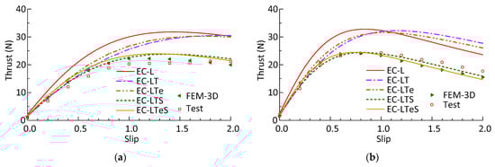
Figure 11.
Calculation, simulation, and test results of thrust: (a) at 60 Hz; (b) at 110 Hz.
When the motor is driven by a constant voltage–frequency inverter, the equivalent circuit with longitudinal end effect (EC-L) has the largest error in the motoring region, compared with other equivalent circuit models. With the increase of slip, the difference between the calculated and the measured value becomes larger, the maximum errors between them are more than 50%, and the average error between them is 52.41% and 34.51% at 60 Hz and 110 Hz, respectively.
The calculation results of the equivalent circuits considering the longitudinal and transverse end effects (EC-LT), including the equivalent circuit with new transverse end effect correction coefficients (EC-LTe), have less error with the simulation and measurement values only when the speed is close to the synchronous speed. The average error of the slip range between the calculated thrust and measured ones is more than 30% at both 60 Hz and 110 Hz. In the motoring region with high slip and the negative braking region, the equivalent circuit cannot meet the calculation accuracy for the motor with a large air-gap-to-pole-pitch ratio due to the large error.
The equivalent circuit considering longitudinal and transverse end effects, skin effect, and secondary leakage reactance can reflect the thrust slip characteristics more accurately. In general, the average errors between the measured and the calculated value of EC-LTS under the two frequencies are 11.68% and 5.85%, respectively, which is smaller than that between the measured and the calculated value of EC-LTeS. The error between the 3D simulation and the measured results is less than 10%. In order to simplify the model and facilitate the calculation, some assumptions are made in the longitudinal, transverse and vertical models, and therefore, there are some errors between the calculated values and the simulation and test values.
5. Conclusions
A novel, improved equivalent circuit model is proposed as a quasi-2D vertical model that considers the vertical distribution of air gap magnetic field and secondary leakage reactance on the basis of traditional equivalent circuits, and the influences on operating characteristics of a DLIM with different equivalent circuit models are fully investigated. Three-dimensional (3D) FEM is used to compare the calculation results in order to verify the proposed equivalent circuit model. The analytical calculations are validated by the measurements on a prototype low-speed DLIM under a constant voltage–frequency drive [30]. Based on the comprehensive comparison in the four equivalent circuit models, conclusions include the following:
- (1)
- Considering the vertical distribution of the magnetic field in the equivalent circuit, two coefficients can be used to modify the secondary resistance and excitation reactance, respectively.
- (2)
- The average errors between FEM calculation and the proposed equivalent circuit results, which considers longitudinal, transverse end effects, and skin effect, are 1.95%, 3.11%, and 5.17% with the mechanical air gap width of 0.0075, 0.0105, and 0.0135 m, respectively, while that of the traditional equivalent circuit (EC-LT) are 10.7%, 13.63%, and 17.33%, respectively; when a new transverse end effect coefficient is used in the equivalent circuit (EC-LTe), the average errors of the thrust are reduced by about 3%.
- (3)
- When the large air gap DLIM is driven by a constant current source with different frequencies, the thrust calculation results of the equivalent circuit, which do not fully consider the correction coefficients of the three direction models, i.e., equivalent circuit model EC-L, EC-LS, and EC-LT(e), have more than 11% errors with the FEM simulation results in the slip range, while the errors between the value of proposed equivalent circuit and simulation are less than 5%. When the DLIM is driven by a constant voltage–frequency inverter, the calculated results of the proposed equivalent circuit are in good agreement with the measured and simulated ones.
- (4)
- The improved equivalent circuit proposed in this paper takes into account the correction coefficients of the longitudinal, transverse, and vertical model of DLIM, which can reflect the thrust characteristics of the motor more accurately, compared with the traditional equivalent circuits, especially for the large air-gap-to-pole-pitch ratio DLIMs.
Author Contributions
Conceptualization, Q.Z. and Z.Z.; methodology, T.S.; validation, Q.Z., T.S. and Z.Z.; formal analysis, investigation, writing—original draft preparation, Q.Z.; data curation, T.S.; writing—review and editing, Q.Z. and H.L.; visualization, T.S.; resources, supervision, project administration, H.L. All authors have read and agreed to the published version of the manuscript.
Funding
This research was funded by the Fundamental Research Funds for the Central Universities, Grant Number 2021YJS159.
Data Availability Statement
Data are contained within the article.
Acknowledgments
Some simulation results are completed by Yu Wang; School of Electrical Engineering, Beijing Jiaotong University.
Conflicts of Interest
The authors declare no conflict of interest.
Appendix A

Table A1.
Specifications of DLIM.
Appendix B
The expressions of constants C1, C2, D1, and D2 in Equations (19)–(27) are as follows:
References
- Boldea, I.; Nasar, S. Linear electric actuators and generators. IEEE Trans. Energy Convers. 1999, 14, 712–717. [Google Scholar] [CrossRef]
- Meeker, D.; Newman, M. Indirect Vector Control of a Redundant Linear Induction Motor for Aircraft Launch. Proc. IEEE 2009, 97, 1768–1776. [Google Scholar] [CrossRef]
- Bertola, L.; Cox, T.; Wheeler, P.; Garvey, S.; Morvan, H. Thermal Design of Linear Induction and Synchronous Motors for Electromagnetic Launch of Civil Aircraft. IEEE Trans. Plasma Sci. 2017, 45, 1146–1153. [Google Scholar] [CrossRef]
- Lv, G.; Zeng, D.; Zhou, T. A Novel MMF Distribution Model for 3-D Analysis of Linear Induction Motor with Asymmetric Cap-Secondary for Metro. IEEE Trans. Magn. 2017, 53, 8107907. [Google Scholar] [CrossRef]
- Lv, G.; Zhou, T.; Zeng, D.; Liu, Z. Influence of Secondary Constructions on Transverse Forces of Linear Induction Motors in Curve Rails for Urban Rail Transit. IEEE Trans. Ind. Electron. 2018, 66, 4231–4239. [Google Scholar] [CrossRef]
- Abdollahi, S.E.; Mirzayee, M.; Mirsalim, M. Design and Analysis of a Double-Sided Linear Induction Motor for Transportation. IEEE Trans. Magn. 2015, 51, 1–7. [Google Scholar] [CrossRef]
- Mihalachi, M.; Leidhold, R.; Mutschler, P. Long primary linear drive for material handling. In Proceedings of the 2009 International Conference on Electrical Machines and Systems, Tokyo, Japan, 15–18 November 2009; pp. 1–6. [Google Scholar]
- Liu, H.; Zhang, Q.; Ma, J. Thrust Characteristics Analysis of Long Primary Double Sided Linear Induction Machine with Plate and Novel Shuttle Secondary Structure. Trans. Nanjing Univ. Aeronaut. Astronaut. 2019, 36, 693–702. [Google Scholar] [CrossRef]
- De Oliveira, R.A.H.; Berger, D.; Schultz, L.; Stephan, R.M.; Ferreira, A.C. Finite element analysis of the forces developed on linear induction motors. In Proceedings of the 2015 IEEE 13th Brazilian Power Electronics Conference and 1st Southern Power Electronics Conference (COBEP/SPEC, Fortaleza, Brazil, 29 November–2 December 2015; pp. 1–6. [Google Scholar]
- Naderi, P.; Shiri, A. Modeling of Ladder-Secondary-Linear Induction Machine Using Magnetic Equivalent Circuit. IEEE Trans. Veh. Technol. 2018, 67, 11411–11419. [Google Scholar] [CrossRef]
- Zeng, D.; Lv, G.; Zhou, T. Equivalent Circuits for Single-Sided Linear Induction Motors with Asymmetric Cap Secondary for Linear Transit. IEEE Trans. Energy Convers. 2018, 33, 1729–1738. [Google Scholar] [CrossRef]
- Isfahani, A.; Ebrahimi, B.; Lesani, H. Design Optimization of a Low-Speed Single-Sided Linear Induction Motor for Improved Efficiency and Power Factor. IEEE Trans. Magn. 2008, 44, 266–272. [Google Scholar] [CrossRef]
- Ravanji, M.H.; Nasiri-Gheidari, Z. Design Optimization of a Ladder Secondary Single-Sided Linear Induction Motor for Improved Performance. IEEE Trans. Energy Convers. 2015, 30, 1595–1603. [Google Scholar] [CrossRef]
- Lee, B.-J.; Koo, D.-H.; Cho, Y.-H. Investigation of Linear Induction Motor According to Secondary Conductor Structure. IEEE Trans. Magn. 2009, 45, 2839–2842. [Google Scholar] [CrossRef]
- Bolton, H. Forces in induction motors with laterally asymmetric sheet secondaries. Proc. Inst. Electr. Eng. 1970, 117, 2241–2248. [Google Scholar] [CrossRef]
- Lv, G.; Zhou, T.; Zeng, D.; Liu, Z. Design of Ladder-Slit Secondaries and Performance Improvement of Linear Induction Motors for Urban Rail Transit. IEEE Trans. Ind. Electron. 2018, 65, 1187–1195. [Google Scholar] [CrossRef]
- Yoshida, K.; Kawamura, I. A method of two-dimensional analysis for short primary linear induction motors. Electr. Eng. Jpn. 1980, 100, 51–59. [Google Scholar] [CrossRef]
- Nonaka, S.; Fujii, N. Simplified two-dimensional analysis of linear induction motors. IEEE Trans. Magn. 1987, 23, 2832–2834. [Google Scholar] [CrossRef]
- Yamamura, S.; Ito, H. Three-dimensional analysis of linear induction motors. Electr. Eng. Jpn. 1976, 96, 55–61. [Google Scholar] [CrossRef]
- Kim, D.-K.; Kwon, B.-I. A Novel Equivalent Circuit Model of Linear Induction Motor Based on Finite Element Analysis and Its Coupling with External Circuits. IEEE Trans. Magn. 2006, 42, 3407–3409. [Google Scholar] [CrossRef]
- Heidari, H.; Rassõlkin, A.; Razzaghi, A.; Vaimann, T.; Kallaste, A.; Andriushchenko, E.; Belahcen, A.; Lukichev, D. A Modified Dynamic Model of Single-Sided Linear Induction Motors Considering Longitudinal and Transversal Effects. Electron. 2021, 10, 933. [Google Scholar] [CrossRef]
- Woronowicz, K.; Safaee, A. A novel linear induction motor equivalent-circuit with optimized end effect model. Can. J. Electr. Comput. Eng. 2014, 37, 34–41. [Google Scholar] [CrossRef]
- Lv, G.; Zeng, D.; Zhou, T. An Advanced Equivalent Circuit Model for Linear Induction Motors. IEEE Trans. Ind. Electron. 2018, 65, 7495–7503. [Google Scholar] [CrossRef]
- Xu, W.; Zhu, J.; Zhang, Y.; Li, Y.; Wang, Y.; Guo, Y. An Improved Equivalent Circuit Model of a Single-Sided Linear Induction Motor. IEEE Trans. Veh. Technol. 2010, 59, 2277–2289. [Google Scholar] [CrossRef] [Green Version]
- Xu, W.; Zhu, J.; Zhang, Y.; Li, Z.; Li, Y.; Wang, Y.; Guo, Y.; Li, Y. Equivalent Circuits for Single-Sided Linear Induction Motors. IEEE Trans. Ind. Appl. 2010, 46, 2410–2423. [Google Scholar] [CrossRef] [Green Version]
- Lu, J.; Ma, W. Research on End Effect of Linear Induction Machine for High-Speed Industrial Transportation. IEEE Trans. Plasma Sci. 2010, 39, 116–120. [Google Scholar] [CrossRef]
- Hirasa, T.; Ishikawa, S.; Yamamuro, T. Equivalent circuit of linear induction motors with end effect taken into account. Electr. Eng. Jpn. 1980, 100, 65–71. [Google Scholar] [CrossRef]
- Bolton, H. Transverse edge effect in sheet-rotor induction motors. Proc. Inst. Electr. Eng. 1969, 116, 725. [Google Scholar] [CrossRef]
- Boldea, I.; Nasar, S.A. The Induction Machine Handbook; CRC Press LLC: Boca Raton, FL, USA, 2002. [Google Scholar]
- Umezu, N.; Nonaka, S. Characteristics of Low-Speed Linear Induction Machines. Electr. Eng. Jpn. 1977, 97, 50–60. [Google Scholar] [CrossRef]

Publisher’s Note: MDPI stays neutral with regard to jurisdictional claims in published maps and institutional affiliations. |
© 2021 by the authors. Licensee MDPI, Basel, Switzerland. This article is an open access article distributed under the terms and conditions of the Creative Commons Attribution (CC BY) license (https://creativecommons.org/licenses/by/4.0/).