Article

Accuracy Improvement in Resolver Offset Detection Based on Angle Tracking Observer with Coordinate Transformation

LG Magna e-Powertrain, Incheon KS006, Korea
*
Author to whom correspondence should be addressed.
Electronics 2021, 10(14), 1643; https://doi.org/10.3390/electronics10141643
Submission received: 31 May 2021 / Revised: 20 June 2021 / Accepted: 5 July 2021 / Published: 10 July 2021
(This article belongs to the Special Issue State-of-the-art Power Electronics in Korea)

Abstract

:
It is necessary to obtain the rotor position of the Interior Permanent Magnet Synchronous Motor (IPMSM) for instantaneous torque control in an electric vehicle system. A resolver is mostly used as a rotor position sensor, each motor has a resolver offset according to the fit tolerance of the resolver pressed into the rotor shaft when the motor is manufactured. This resolver offset is having a huge effect on IPMSM output characteristics. Therefore, resolver offset detection equipment with a method for high precision of detection is required in production lines in order to make uniform characteristics of IPMSM. It is also necessary to have robust performance in many different kinds of the noise of equipment in the production line. This paper presents a highly precise Resolver to Digital Converter (RDC) that is implemented with LabVIEW of National Instruments and a resolver offset detecting method that has the robust performance to noise based on coordinate transformation algorithm. Experiments with and without the proposed method were performed and a comparative analysis is conducted to test the validity.

1. Introduction

The IPMSM has been widely used in electric vehicles for its high power density and high speed driving characteristics [1,2,3,4,5]. IPMSM must obtain a rotor position with a position sensor to instantaneous torque control. A resolver which is a robust position sensor about physical vibration and shock is most commonly used in electric vehicles. It is pressed in the shaft of IPMSM and detects position by rotating in synchronization with a rotor [6,7,8,9,10,11,12]. Mass-produced motors certainly have a resolver fit tolerance when each resolver is pressed into the rotor shaft. The tolerance occurs to resolver offset and this offset occurs to torque tolerance as Figure 1. In production, the resolver offset should be precisely measured and the offset should be applied in motor control.
Several studies on detecting resolver offset in stationary state [13,14,15,16] have been performed and a lot of sensorless methods [17,18,19] that estimate resolver position without position sensor were done. However, these kinds of methods require an inverter and a power supply providing DC power to the inverter, therefore, these are not appropriate for production line limited in space. Moreover, sensorless methods are unable to apply when high precision under electric angle 0.6 tolerance is required. So resolver offset measuring equipment to apply in production line should be measured without inverter precisely. It is also required to have a robust performance to many different kinds of the noise of equipment in production line. This paper presents a highly precise RDC that is implemented with LabVIEW of National Instruments and a resolver offset detecting method that has the robust performance to noise applying coordinate transformation algorithm. Experiments with and without the proposed method were performed and a comparative analysis is conducted to test the validity.

2. Resolver to Digital Converter

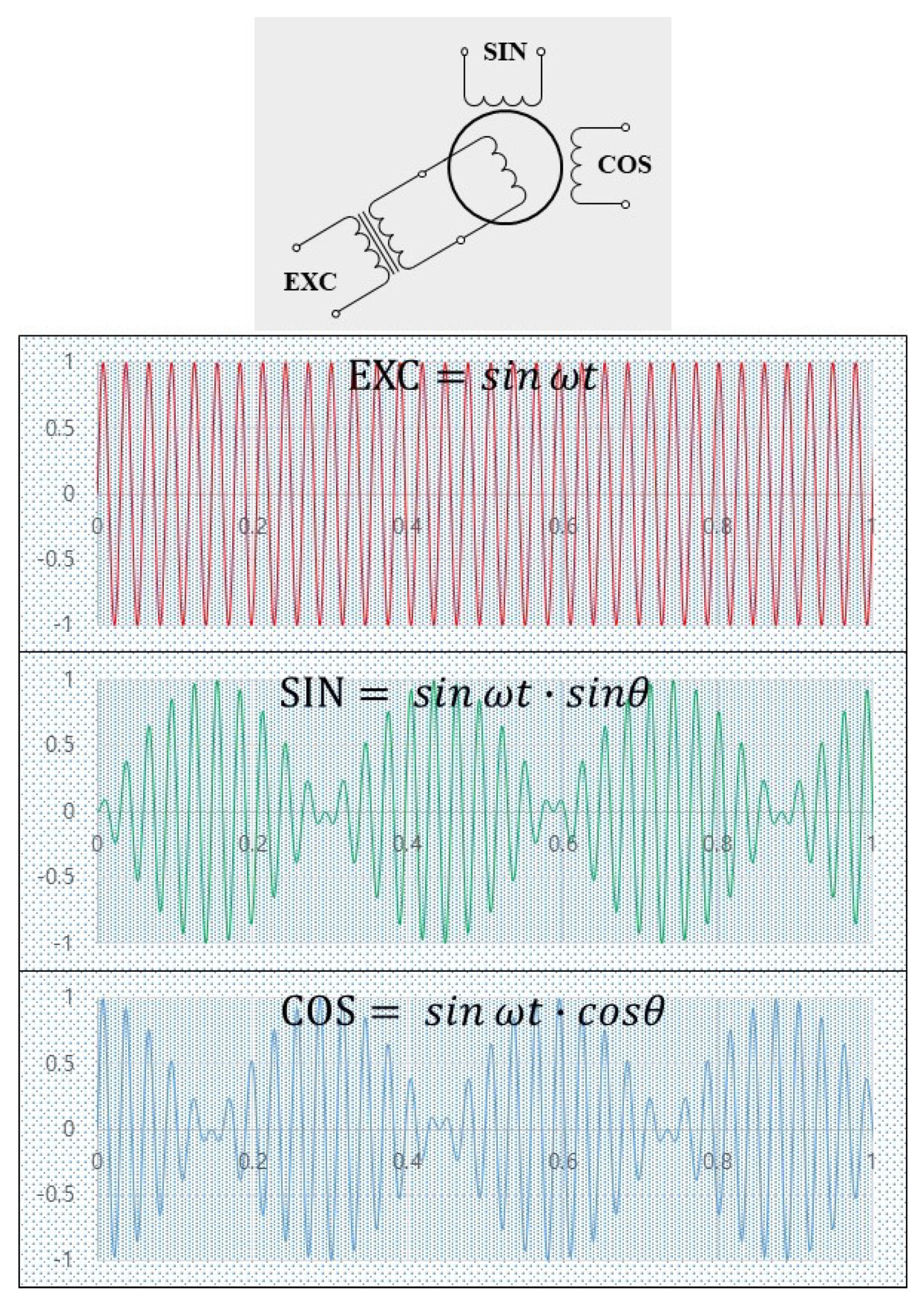
2.1. Method to Detecting Position with Resolver

As previously mentioned, a resolver has been widely used in electric vehicles to obtain the absolute position of the rotor for instantaneous torque control with vector control. Resolver, an analog type of absolute position sensor, is a kind of rotary transformer connected to the motor shaft and outputs an alternating voltage according to rotor position. Resolver structure and input/output consists of stator, rotor, and rotating transformer as Figure 2.
A rotor winding, a primary winding of a resolver, is EXC(Excitation signal) and two stator windings with 90-degree angle difference are secondary windings of a resolver. The principle of the resolver is EXC winding acts as the input for an AC drive signal and each of the secondary windings is used as output windings as Figure 2. Through these signals, the position of the resolver axis, in other words, the position of rotor θ can be obtained. Each of the signals of secondary windings varies depending on primary axis θ . Once analog voltage sin ω t is excited to EXC, following two signals can be obtained in rotor windings.
S I N = s i n ( ω t ) s i n ( θ ) C O S = s i n ( ω t ) c o s ( θ )
Through the ratio of these two signals, the absolute angle θ of the rotor connected to the resolver shaft can be obtained as follows.
θ e = t a n 1 ( s i n ( ω t ) s i n ( θ ) s i n ( ω t ) c o s ( θ ) )
However, this method of obtaining the position of the rotor is vulnerable to noise. Therefore, it is difficult to apply to systems that require precise rotor position obtaining.

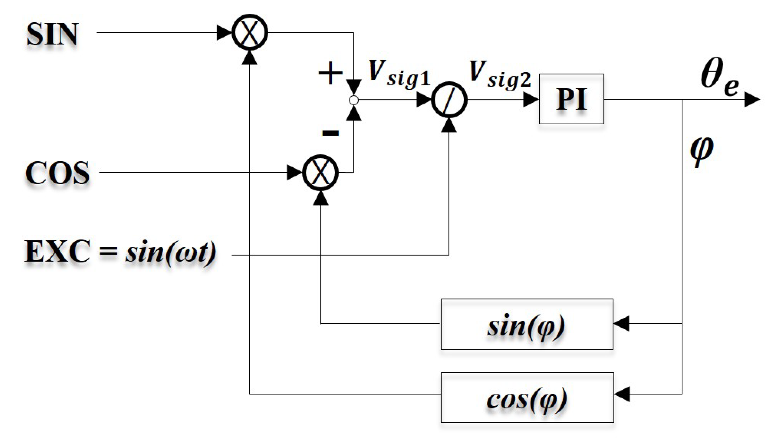
2.2. Angle Tracking Observer (ATO)

Input/Output signals of a resolver are connected to RDC which is made up of a single IC and it detects rotor position. To apply commercial RDC to the motor production line, there needs to be an additional circuit, which means more space is required for the hardware of RDC.
RDC can be substituted using National Instruments PCI which consists of DAC (Digital to Analog Converter), ADC( Analog to Digital Converter) functions with LabVIEW software where the rotor position detecting algorithm can be implemented. The absolute position of the rotor can be detected based on SIN and COS signals from the ADC function, which are electrical reactions of EXC signal that sent from DAC to the resolver. As previously mentioned this method easily detects the position of the rotor; however, it is vulnerable to noise so it is improper to apply to a production line. ATO is the algorithm that feedbacks the rotor position through the PI controller and tracking the rotor position as Figure 3. Each SIN and COS signal is multiplied with ATO feedback value sin( φ ) and cos( φ ). V s i g 1 can be expressed as subtracting these equations.
V s i g 1 = [ s i n ( θ ) s i n ( ω t ) c o s ( φ ) ] [ c o s ( θ ) s i n ( ω t ) s i n ( φ ) ]
Solving Equation (3):
V s i g 1 = s i n ( ω t ) s i n ( θ φ )
Dividing EXC signal s i n ω t , V s i g 2 can be expressed as follows:
V s i g 2 = s i n ( θ e φ )
V s i g 2 is entered PI controller and it controls to reduce V s i g 2 value to zero. With an adequate gain of the PI controller, the PI controller corrects θ e φ value to zero using a feedback loop, and finally, the value becomes θ e = φ . This kind of method has noise-robust characteristics.

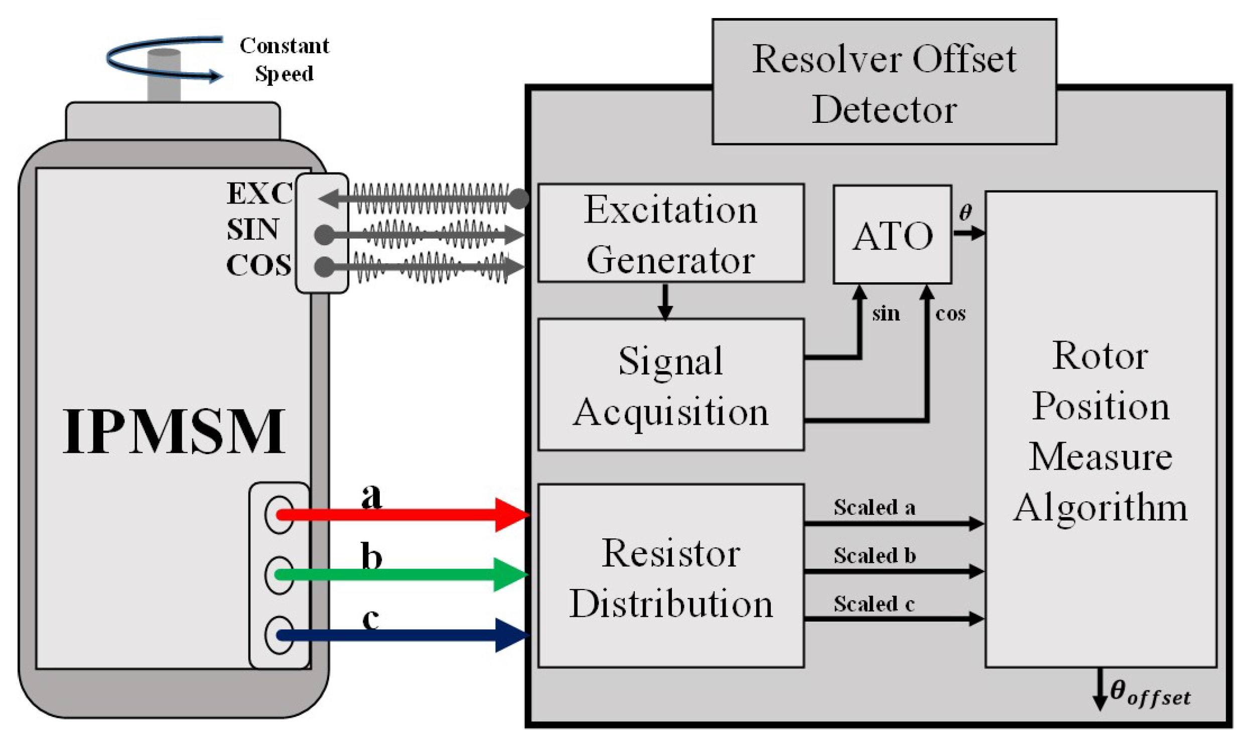
3. Resolver Offset Detection Method

To instantaneously control the torque of IPMSM, using rotating reference frame which has the speed of the rotor, the inverter converts stator current. The position of the rotor θ e is required for conversion into a rotating reference frame, and this is mainly detected with a resolver in an electric vehicle system. θ e detected by a resolver is placed as rotating reference frame d e axis, the inverter converts the stator current to the rotating reference frame. Figure 4 is IPMSM torque control system. With θ e detected by a resolver and 3 phase current i a , i b , i c , torque control is performed after coordinate transformation through θ e .

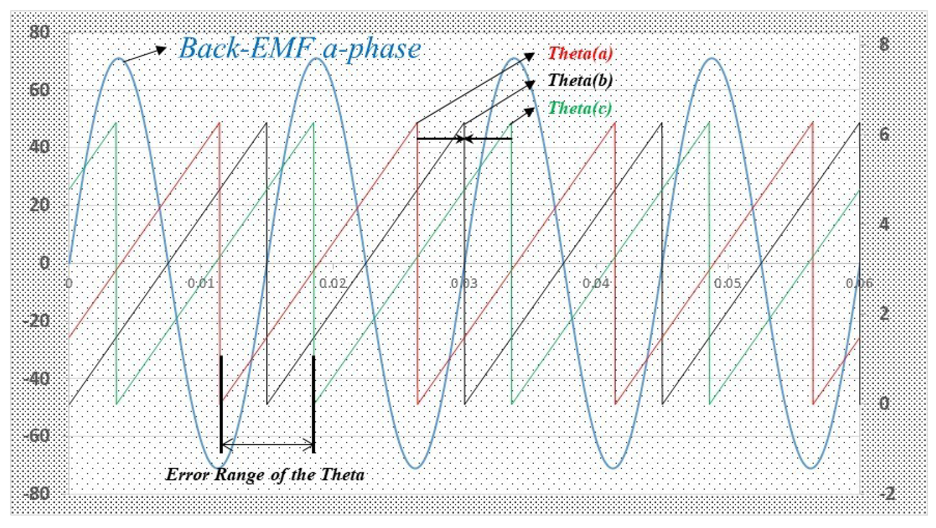
3.1. A-Phase, Theta Zero-Cross Point Detection Method

Torque T e of IPMSM is expressed as follows:
T e = 3 2 P 2 [ ( ϕ f i q s r + ( L d L q ) i d s r i q s r ]
where, P: Number of pole, ϕ f : Magnetic flux of permanent magnet, L d s : d-axis inductance, L q s : q-axis inductance.
As you can know the fact from torque equation and Figure 4, inadequately measured θ e affects i d s e , i q s e and it has a negative effect on torque accuracy. Torque accuracy of the inverter is required under 5% between command and output torque for electric vehicle IPMSM. Stator current I s is expressed as follows.
I s = ( i d s e + i q s e )
If stator current exceeds 500 [A], θ e only have a margin of 0.6 in electrical angle to meet output torque accuracy under 5%. Therefore, the resolver offset error measured in motor production must be under 0.6 in electrical angle.
As previously mentioned, the rotor position θ e must be synchronized with θ e on a-phase Back-EMF(Back-Electro Motive Force) of IPMSM. In other words, the process of measuring and applying the resolver offset can be done by applying offset value to θ e to synchronize θ e with the angle of the a-phase Back-EMF. Figure 5 shows the a-phase Back-EMF of IPMSM rotating 1000 [rpm] and θ e output by the resolver. Since the initial angular error from the mechanical tolerance is determined when the resolver is inserted to the shaft of the IPMSM, there will be no more mechanical position error changes. Distance between Theta(a) and Theta(c) is the maximum error value so each has a phase difference with Back-EMF, while theta(b) is the same phase with a-phase Back-EMF and has no phase difference with it. Therefore, it is necessary to detect the angular difference between θ e and Theta(b), and the method to find this difference based on the zero-cross point of a-phase Back-EMF is called Zero-cross point detection method. This zero-cross point detection method can easily detect the angular difference but it is vulnerable to the noise in Back-EMF measurement.

3.2. Detection Method with Coordinate Transformation

In general, a voltage induced by Back-EMF has intense noise, which components vary according to the motor rotation. Analog and digital filters could be applied to reduce these noise components but it is impossible to select a cut-off frequency since the frequency of back-EMF voltage varies.
The coordinate transformation is being used widely as transforming AC voltage or current signal to DC signal. As you can see in Figure 4, it is used in the motor control field for vector control. The transforming process of 3-phase voltage to d-q axes in the stationary reference frame voltage is shown below. First of all, 3-phase equilibrium voltage is assumed to be:
v a s = V m c o s ( ω t ) v b s = V m c o s ( ω t 120 ) v c s = V m c o s ( ω t + 120 )
3-phase equilibrium voltage is represented by d s q s axes voltage in the stationary reference frame as follows:
v d s s = ( 2 v a s v b s v c s 3 ) = v a s = V m c o s ( ω e t ) v q s s = 1 3 ( v b s v c s ) = V m s i n ( ω e t ) v n s s = 2 ( v a s + v b s + v c s ) 3 = 0
Converting 3-phase alternative variable with 120 phase difference to d s q s axes stationary reference frame, two variables are written where equal magnitudes and 90 phase differences. Reformulate d q axes components in the stationary reference frame to rotating reference as follows:
v d s e = v d s s c o s ( θ e ) + v q s e s i n ( θ e ) = V m c o s ( ω e t ) c o s ( θ e ) + V m s i n ( ω e t ) s i n ( ω e ) = V m v q s e = v d s s s i n ( θ e ) + v q s e c o s ( θ e ) = V m c o s ( ω e t ) s i n ( θ e ) + V m s i n ( ω e t ) s i n ( ω e ) = 0
3-phase AC variables are expressed as DC values in a rotating reference frame that rotates at the frequency of the AC, and their magnitudes become the maximum value of the AC variables. Figure 6 illustrates the previously described coordinate transformations.
As you can see in Figure 6, v q s e becomes zero when θ e is correspond with rotor speed. Therefore, the offset value of θ e which is used to transform 3-phase Back-EMF should be set to make v q s e to zero. In addition, since v q s e is DC value, there are fewer limits of select cut-off frequency to apply a filter and not required compensation of distorted signals so it is robust to noise.

4. The Result of the Experiment and Analysis

4.1. The Result of the Experiment

Among the resolver offset detection methods, the application of ATO for resolver signal processing is robust to noise without additional circuit. In addition, its coordinate transformation is much more robust to noise than comparing Back-EMF and θ e technique as described before. In this section, performance comparisons were performed for ATO and t a n 1 techniques, and the comparison of zero-cross point and coordinate transformation-based techniques are also presented.
The system block diagram for the proposed resolver offset detection technique is shown in Figure 7. 3-phase Back-EMF is induced when the external motor rotates target IPMSM at a specific speed, and the resolver offset detector measures the 3-phase Back-EMF. The detector sends an EXC signal to the resolver of IPMSM and receives SIN and COS signals from the resolver. After that, ATO obtains SIN and COS signals and output θ . Back-EMF voltages are distributed by the distribution resistor to make the appropriate voltage of the sensing board in the rotor position measure algorithm. The rotor position measure algorithm receives 3-phase Back-EMF and θ e to perform coordinate transformation and output resolver offset value which makes v q s e to zero.
The resolver offset detection system is executed at the End of production line and it is included in EOL (End of Line) tests. EOL tests are responsible for testing the overall functionality of the motor before it is delivered and comprised of Back-EMF/1000 [rpm] test, hi-pot test, stator and resolver resistance test, resolver offset detector, and so on. Since tests and controls are carried out by PCI for EOL tests, it is possible to implement a resolver offset detector with LabVIEW. There is no need to add more hardware because the hardware is already configured for Back-EMF and resolver resistance detection. Figure 8 shows the results of implementing the Resolver offset detector ATO and Rotor position measure algorithm in Labview.
Specifications of the experiment IPMSM are 120 [kW], 8-pole and v r m s / k r p m is 42 [V]. Ten motors are used to check the resolver offset detection accuracy, one motor is used to check repeatability. Resolver offset value is represented with 0 to 2 ϕ (0 to 360 ) and it is converted to digital 12 bit (0 to 4095) to apply to an MCU (Micro Control Unit) calculation.
First of all, experiment results of θ finding using the t a n 1 method are shown in Figure 9. θ e measured 44 periods, and is at a distorted maximum 0.045 (electrical angle) on zero points even if the experiment environment is not affected by the noise of production equipment. It is expected that accurate measurement of the resolver offset through this method will be difficult.
Back-EMF, this too, is not independent of noise. Waveforms in Figure 10 are Back-EMF of a-phase overlaid 8 periods driven on 200 [rpm]. Figure 10a does not include distortion of noise and Figure 10b does include. As shown in Figure 10, to detect the resolver offset using a method that compares a-phase zero-cross point with θ e , a filter must be applied on this kind of method.
The resolver offset detection technique using proposed ATO and coordinate transformation has only small error from the noise and it is possible to measure accurate resolver offset using an appropriate filter on Back-EMF. Figure 11 is the experiment results using proposed ATO and coordinate transformation. Figure 11a shows v q s e and v q s e * command which makes θ e to zero. As shown in this figure, the value of v q s e * for the process starts with the q-axis value that causes the maximum position error in the current estimated position. Based on the initial error in this process, open-loop compensation is conducted based on the mean value of formal processes. Then, the proposed closed-loop algorithm eliminates the small error left from the formal process. Based on this last process, the final resolver offset value is obtained, in the case of Figure 11, 1582 which means 139.043 in electrical angle. Figure 11b shows the a-phase Back-EMF with the estimated rotor position in the first step of the process, when the q-axis voltage causes the maximum position error is injected. From the result of the estimated position in this figure, it can be noticed that a-phase Back-EMF and θ e have a huge phase difference in this initial process. Figure 11c shows the a-phase Back-EMF and θ e when the proposed closed-loop estimation process is finished. The angle in this figure is almost identical to the angle of the a-phase Back-EMF, which ensures that the measured resolver offset value through the coordinate transformation is valid. Figure 11d shows SIN and COS signal output by a resolver during the process.

4.2. Analysis of the Experiment

To verify the resolver offset detecting method proposed in this paper, a comparison experiment was performed in the production line. There is a process to determine whether the overall functionality of the motor is normal or not by measuring Back-EMF at 1000 [rpm] during the production process, so if the process of measuring the resolver offset is performed at the same time, it is possible to perform the detecting method in parallel without adding additional tac-time. Therefore comparative experiment for detecting resolver offset was measured during rotation at 1000 [rpm], and the offset value was measured by comparing 100 cycles of Back-EMF and θ e in one measurement. The test motors are ten identically produced IPMSM.
The experiment conditions are shown in Table 1.
There are two ways to convert the resolver signal to θ e : using t a n 1 or ATO algorithm. There are also two ways to detect resolver offset: comparing a-phase Back-EMF or using coordinate transformation. These can result in a combination of four detecting methods. The results of the experiment using these four methods are shown in Figure 12. #10 sample is the sample where 1503 is the correct offset value, it is true value verified by inverter and 1500 to 1506 is allowable tolerance. As shown in Figure 12, 81% of the combination of t a n 1 and a-phase Back-EMF method exceeds the error range, the distribution appears normal but has a large standard deviation at 11.2262, and even if the sample mean value is 1496.45, the value and true value are different.
On the other hand, combination of the ATO and coordinate transformation does never exceed the error range, has low standard deviation at 0.5024 and all offset values are measured in 1503 or 1504. The offset errors of 1503 or 1504 are errors levels that inevitably occur by converting 0 to 2 π ( 0 to 360 ) into 12 bit.
When the true value of the experiment results of the ten samples shown in Figure 12 is zero, the result of expressing the overall experiment results are shown in Figure 13. Like previous results, it can be seen that the rest of the methods except the combination of the ATO and coordinate transformation exceed the error range from 54.7% to 83.7%. However, the proposed method of the resolver offset detection in this paper tends not to exceed the error range during the whole experiments.

5. Conclusions

In this paper, a high precision resolver offset detection method is implemented to apply to the vehicle IPMSM production line and we proposed the detection method which is robust to noise using the coordinate transformation algorithm. Experiments were performed with and without the proposed algorithm, and these were compared and analyzed to verify the validity of the proposed method. It is confirmed that the accuracy and reliability of the resolver offset measurement are excellent, regardless of the measurement speed and noise, compared to the position detection method comparing a-phase Back-EMF and t a n 1 . Moreover, the total tact-time is improved by reducing the detecting time in EOL by measuring resolver offset simultaneously with the motor back-EMF. A high level of torque accuracy can be satisfied with the proposed resolver offset detecting method; we believe that the method will be applied not only to electric vehicles but also to various systems that apply resolvers.

Author Contributions

Conceptualization, D.-Y.K.; formal analysis, visualization and writing—original draft preparation, D.-Y.K.; experiment, M.-H.K.; validation, M.-H.K.; writing—review and editing, M.-H.K. and D.-Y.K. All authors have contributed to the manuscript. All authors have contributed to the manuscript. All authors have read and agreed to the published version of the manuscript.

Funding

This research received no external funding.

Conflicts of Interest

The authors declare no conflict of interest.

References

  1. Shao, L.; Karci, A.E.H.; Tavernini, D.; Sorniotti, A.; Cheng, M. Design Approaches and Control Strategies for Energy-Efficient Electric Machines for Electric Vehicles—A Review. IEEE Access 2020, 8, 5639–5646. [Google Scholar] [CrossRef]
  2. Khanh, P.Q.; Truong, V.A.; Anh, H.P.H. Extended Permanent Magnet Synchronous Motors Speed Range Based on the Active and Reactive Power Control of Inverters. Energies 2021, 14, 3549. [Google Scholar] [CrossRef]
  3. Kang, L.; Jiang, D.; Xia, C.; Xu, Y.; Sun, K. Research and Analysis of Permanent Magnet Transmission System Controls on Diesel Railway Vehicles. Electronics 2021, 10, 173. [Google Scholar] [CrossRef]
  4. Park, G.; Kim, G.; Gu, B.-G. Sensorless PMSM Drive Inductance Estimation Based on a Data-Driven Approach. Electronics 2021, 10, 791. [Google Scholar] [CrossRef]
  5. Kim, D.-Y.; Lee, J.-H. Low Cost Simple Look-Up Table-Based PMSM Drive Considering DC-Link Voltage Variation. Energies 2020, 13, 3904. [Google Scholar] [CrossRef]
  6. Datlinger, C.; Hirz, M. Benchmark of Rotor Position Sensor Technologies for Application in Automotive Electric Drive Trains. Electronics 2020, 9, 1063. [Google Scholar] [CrossRef]
  7. Datlinger, C.; Hirz, M. An Extended Approach for Validation and Optimization of Position Sensor Signal Processing in Electric Drive Trains. Electronics 2019, 8, 77. [Google Scholar] [CrossRef] [Green Version]
  8. Gaechter, J.; Hirz, M. Evaluation and Modeling of Rotor Position Sensor Characteristics for Electric Traction Motors. SAE Tech. Pap. 2016. [Google Scholar] [CrossRef]
  9. Datlinger, C.; Hirz, M. Investigations of Rotor Shaft Position Sensor Signal Processing in Electric Drive Train Systems. In Proceedings of the 2018 IEEE Transportation Electrification Conference and Expo, Asia-Pacific (ITEC Asia-Pacific), Bangkok, Thailand, 6–9 June 2018; pp. 1–5. [Google Scholar]
  10. Hwang, S.; Kim, H.; Kim, J.; Liu, L.; Li, H. Compensation of Amplitude Imbalance and Imperfect Quadrature in Resolver Signals for PMSM Drives. IEEE Trans. Ind. Appl. 2011, 47, 134–143. [Google Scholar] [CrossRef]
  11. Jin, C.-S.; Jang, I.-S.; Bae, J.-N.; Lee, J.; Kim, W.-H. Proposal of improved winding method for VR resolver. IEEE Trans. Magn. 2015, 51, 1–4. [Google Scholar]
  12. Idkhajine, L.; Monmasson, E.; Naouar, M.W.; Prata, A.; Bouallaga, K. Fully Integrated FPGA-Based Controller for Synchronous Motor Drive. IEEE Trans. Ind. Electron. 2009, 56, 4006–4017. [Google Scholar] [CrossRef]
  13. Bang, J.S.; Kim, T.S. Automatic calibration of a resolver offset of permanent magnet synchronous motors for hybrid electric vehicles. In Proceedings of the 2015 American Control Conference (ACC), Chicago, IL, USA, 1–3 July 2015; pp. 4174–4179. [Google Scholar]
  14. Noori, N.; Khaburi, D.A. Diagnosis and compensation of amplitude imbalance, imperfect quadrant and offset in resolver signals. In Proceedings of the 2016 7th Power Electronics and Drive Systems Technologies Conference (PEDSTC), Tehran, Iran, 16–18 February 2016; pp. 76–81. [Google Scholar]
  15. Katakura, M.; Toda, A.; Takagi, Y.; Suzuki, N.; Kadoyama, T.; Kushihara, H. A 12-bits resolver-to-digital converter using complex twin PLL for accurate mechanical angle measurement. In Proceedings of the Digest of Technical Papers. 2005 Symposium on VLSI Circuits, Kyoto, Japan, 16–18 June 2005; pp. 236–239. [Google Scholar]
  16. Wu, Z.; Li, Y. High-Accuracy Automatic Calibration of Resolver Signals via Two-Step Gradient Estimators. IEEE Sens. J. 2018, 18, 2883–2891. [Google Scholar] [CrossRef]
  17. Shinnaka, S.; Takeuchi, S. A New Sensorless Drive Control System for Transmissionless EVs Using a Permanent-Magnet Synchronous Motor. World Electr. Veh. J. 2007, 2007, 1–9. [Google Scholar] [CrossRef]
  18. Bae, B.H.; Sul, S.K.; Kwon, J.H.; Byeon, J.S. Implementation of sensorless vector control for super-high-speed PMSM of turbo-compressor. IEEE Trans. Ind. Appl. 2003, 39, 811–818. [Google Scholar] [CrossRef]
  19. García, R.C.; Pinto, J.O.P.; Belini, A.B. Estimation of Angular Speed and Park Matrix from Resolver Position Sensor Signals without Using Trigonometric Functions. In Proceedings of the 2018 IEEE XXV International Conference on Electronics, Electrical Engineering and Computing (INTERCON), Lima, Peru, 8–10 August 2018; pp. 1–4. [Google Scholar]
Figure 1. Torque variation due to difference of resolver offset.
Electronics 10 01643 g001
Figure 2. Characteristics of resolver.
Electronics 10 01643 g002
Figure 3. ATO algorithm block diagram.
Electronics 10 01643 g003
Figure 4. Torque control system of IPMSM.
Electronics 10 01643 g004
Figure 5. Back-EMF and Theta ( θ e ).
Electronics 10 01643 g005
Figure 6. d-q axis transformation.
Electronics 10 01643 g006
Figure 7. Resolver offset measure system.
Electronics 10 01643 g007
Figure 8. ATO and Resolver offset measure algorithm.
Electronics 10 01643 g008
Figure 9. θ e ’s data 44 cycle using t a n 1 method.
Electronics 10 01643 g009
Figure 10. Back-EMF a-phase at 200 [rpm].
Electronics 10 01643 g010
Figure 11. Graphic user interface of proposal method (ATO and axis transformation).
Electronics 10 01643 g011
Figure 12. Normal distribution and capability analysis.
Electronics 10 01643 g012aElectronics 10 01643 g012b
Figure 13. Overall normal distribution and capability analysis.
Electronics 10 01643 g013
Table 1. Experiment condition.
ParametersValueUnit
Number of IPMSM10EA
speed1000rpm
v r p m / k r p m 42V
Measurement of time100/1.5Period/s
Pole pair4-
Publisher’s Note: MDPI stays neutral with regard to jurisdictional claims in published maps and institutional affiliations.

