
A Comparison Review on Transmission Mode for Onshore Integration of Offshore Wind Farms: HVDC or HVAC


Abstract
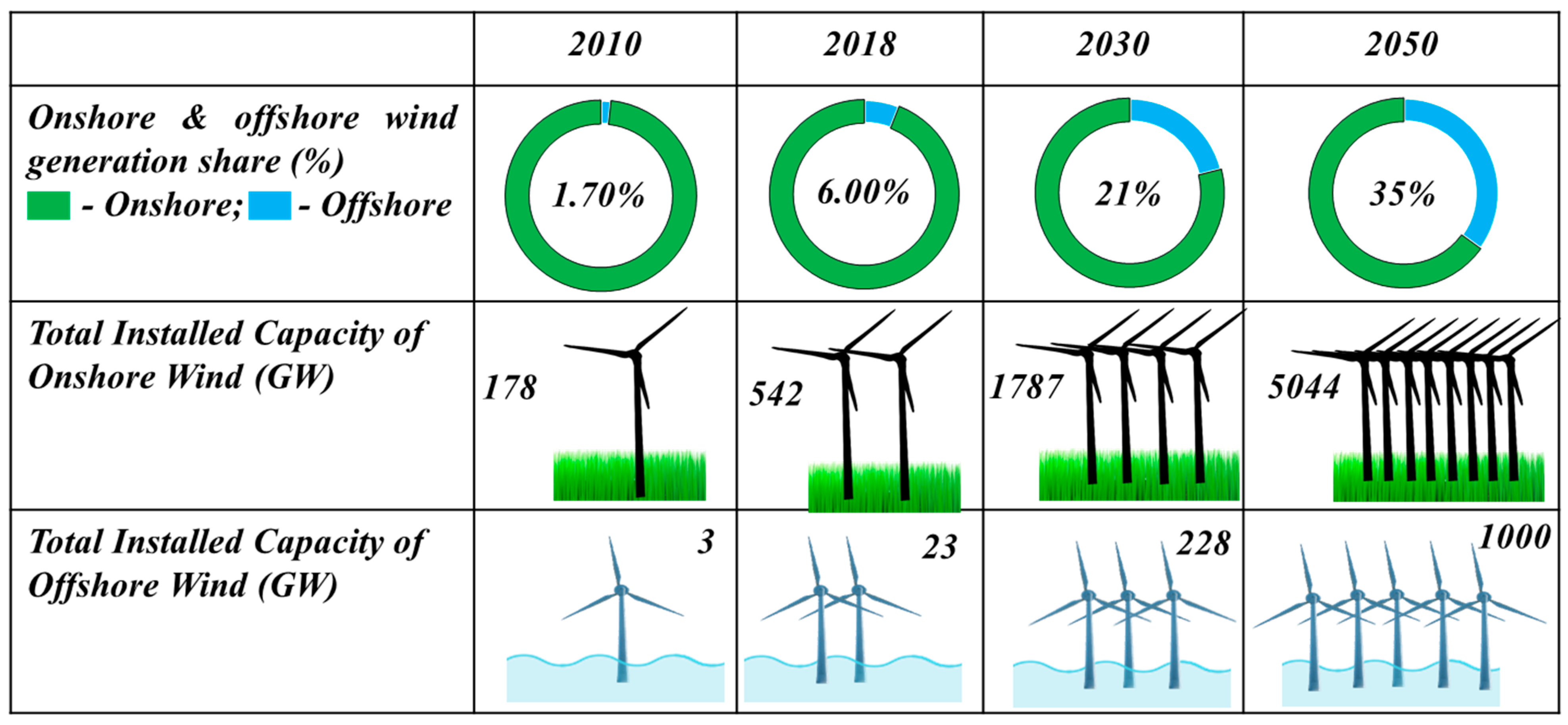
:1. Introduction
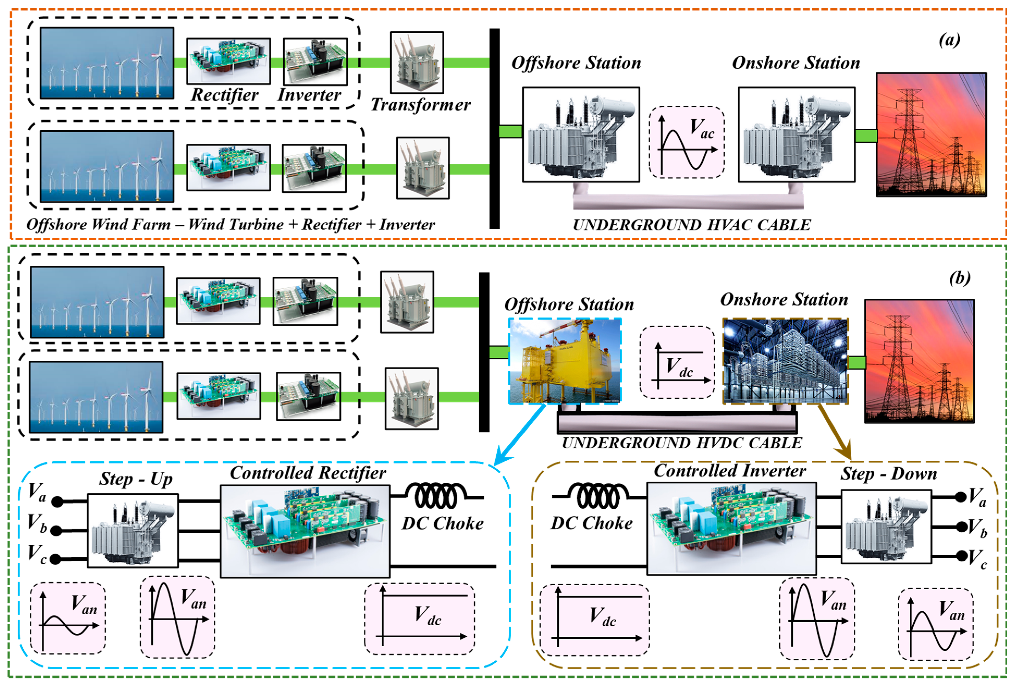
2. Power Layout for Integration of Offshore Wind Farm
3. Grid Side Requirements of Offshore WF
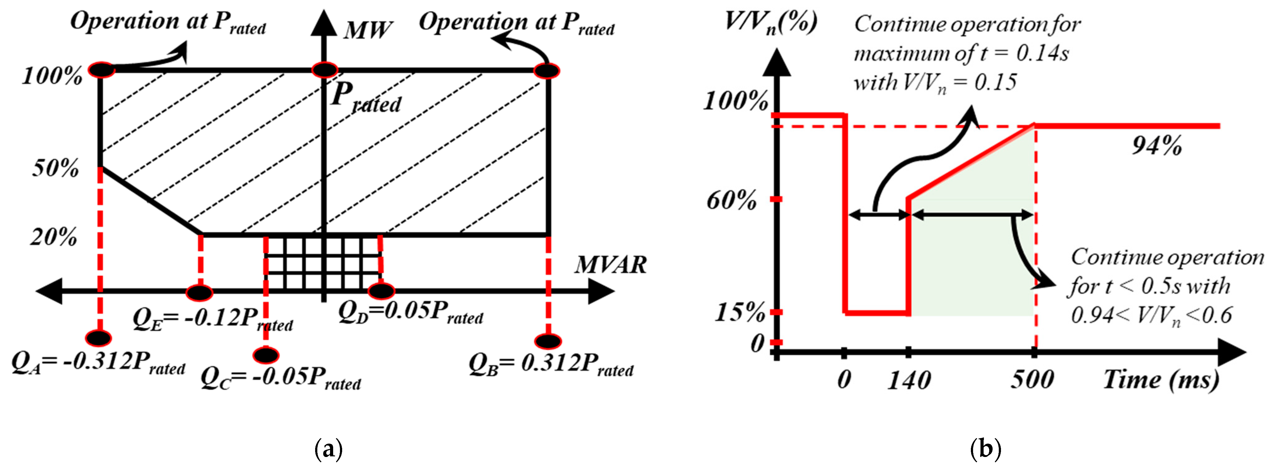
3.1. Voltage or Reactive Power Control Capability
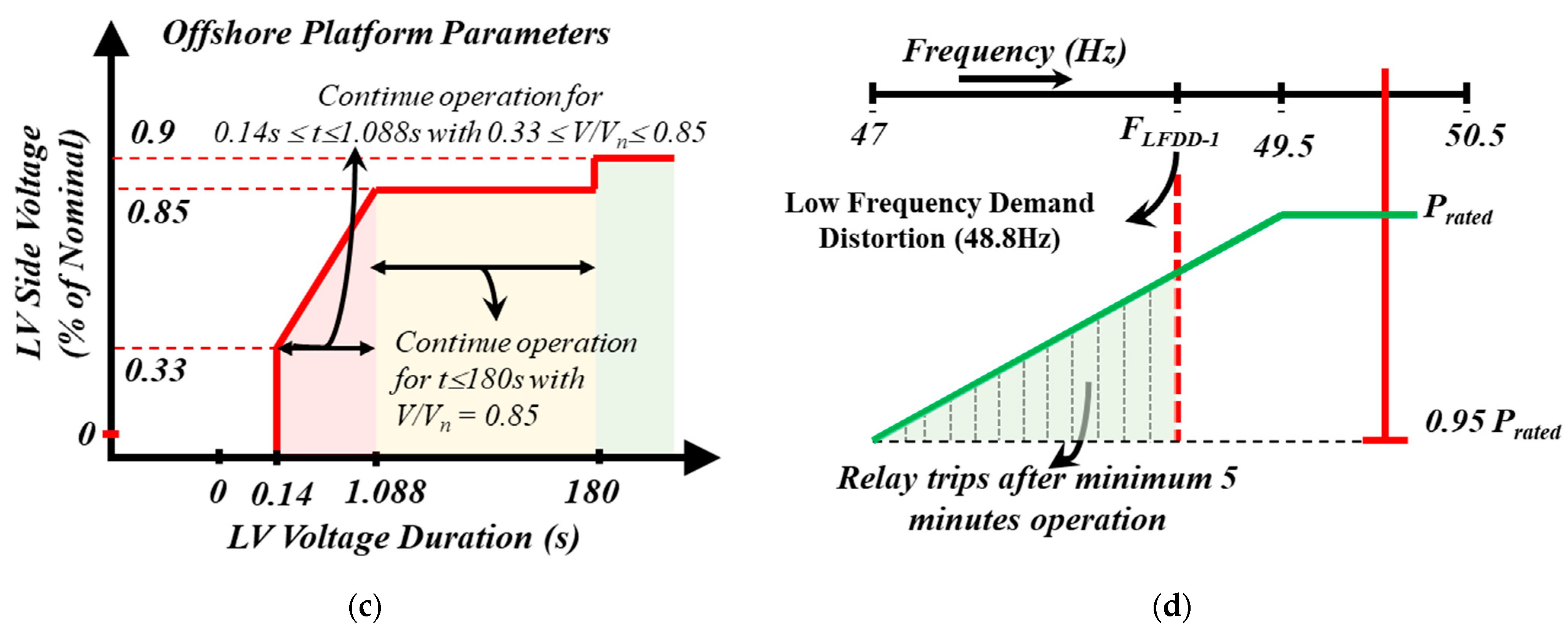
3.2. Fault Ride-Through (FRT) Capability
3.3. Active Power vs. Frequency Control
- -
- DC faults must not completely disrupt the entire system.
- -
- Voltage stabilization and frequency support must be provided by the offshore system to the onshore AC grid.
3.4. Black Start Capability
4. Different Topologies for Offshore Wind Farm
5. AC Vs DC Transmission Choice for Offshore Wind Farm
5.1. Technology Comparison
5.2. Conductor Configurations for HVAC and HVDC Systems
5.3. Cost Comparison
6. Conclusions
Author Contributions
Funding
Data Availability Statement
Conflicts of Interest
References
- IRENA. Deployment, investment, technology, grid integration and socio-economic aspects. In Future of Wind; International Renewable Energy Agency: Abu Dhabi, United Arab Emirates, 2019. [Google Scholar]
- Panwar, N.; Kaushik, S.; Kothari, S. Role of renewable energy sources in environmental protection: A review. Renew. Sustain. Energy Rev. 2011, 15, 1513–1524. [Google Scholar] [CrossRef]
- Billinton, R. Bagen Reliability Considerations in the Utilization of Wind Energy, Solar Energy and Energy Storage in Electric Power Systems. In Proceedings of the 2006 International Conference on Probabilistic Methods Applied to Power Systems, Stockholm, Sweden, 11–15 June 2006; pp. 1–6. [Google Scholar]
- Yang, Y.; Bremner, S.; Menictas, C.; Kay, M. Battery energy storage system size determination in renewable energy systems: A review. Renew. Sustain. Energy Rev. 2018, 91, 109–125. [Google Scholar] [CrossRef]
- Keck, F.; Lenzen, M.; Vassallo, A.; Li, M. The impact of battery energy storage for renewable energy power grids in Australia. Energy 2019, 173, 647–657. [Google Scholar] [CrossRef]
- Chen, Z.; Guerrero, J.M.; Blaabjerg, F. A review of the state of the art of power electronics for wind turbines. IEEE Trans. Power Electron. 2009, 24, 1859–1875. [Google Scholar] [CrossRef]
- Blaabjerg, F.; Liserre, M.; Ma, K. Power Electronics Converters for Wind Turbine Systems. IEEE Trans. Ind. Appl. 2012, 48, 708–719. [Google Scholar] [CrossRef] [Green Version]
- Yaramasu, V.; Wu, B.; Sen, P.C.; Kouro, S.; Narimani, M. High-power wind energy conversion systems: State-of-the-art and emerging technologies. Proc. IEEE 2015, 103, 740–788. [Google Scholar] [CrossRef]
- Erlich, I.; Shewarega, F.; Feltes, C.; Koch, F.W.; Fortmann, J. Offshore Wind Power Generation Technologies. Proc. IEEE 2013, 101, 891–905. [Google Scholar] [CrossRef]
- Gao, Z.; Liu, X. An Overview on Fault Diagnosis, Prognosis and Resilient Control for Wind Turbine Systems. Processes 2021, 9, 300. [Google Scholar] [CrossRef]
- Kaldellis, J.; Apostolou, D. Life cycle energy and carbon footprint of offshore wind energy. Comparison with onshore counterpart. Renew. Energy 2017, 108, 72–84. [Google Scholar] [CrossRef]
- Anuta, H.; Ralon, P.; Taylor, M.; La Camera, F. Renewable Power Generation Costs in 2018; IRENA: Abu Dhabi, United Arab Emirates, 2019. [Google Scholar]
- Watson, S.; Moro, A.; Reis, V.; Baniotopoulos, C.; Barth, S.; Bartoli, G.; Bauer, F.; Boelman, E.; Bosse, D.; Cherubini, A.; et al. Future emerging technologies in the wind power sector: A European perspective. Renew. Sustain. Energy Rev. 2019, 113, 109270. [Google Scholar] [CrossRef]
- Sun, X.; Huang, D.; Wu, G. The current state of offshore wind energy technology development. Energy 2012, 41, 298–312. [Google Scholar] [CrossRef]
- Anaya-Lara, O.; Tande, J.O.; Uhlen, K.; Merz, K. Offshore Wind Energy Technology; Wiley: Hoboken, NJ, USA, 2018. [Google Scholar]
- Ahmad, H. Offshore Wind Park Connection to an HVDC Platform, without Using an AC Collector Platform; Gotl Univ Sweden; 2012; Available online: http://www.diva-portal.org/smash/get/diva2:617719/FULLTEXT01.pdf (accessed on 1 March 2021).
- Ackermann, T.; Ancell, G.; Borup, L.; Eriksen, P.; Ernst, B.; Groome, F.; Lange, M.; Mohrlen, C.; Orths, A.; O’Sullivan, J.; et al. Where the wind blows. IEEE Power Energy Mag. 2009, 7, 65–75. [Google Scholar] [CrossRef]
- Bilgili, M.; Yasar, A.; Simsek, E. Offshore wind power development in Europe and its comparison with onshore counterpart. Renew. Sustain. Energy Rev. 2011, 15, 905–915. [Google Scholar] [CrossRef]
- Gonzalez-Rodriguez, A.G. Review of offshore wind farm cost components. Energy Sustain. Dev. 2017, 37, 10–19. [Google Scholar] [CrossRef]
- Snyder, B.; Kaiser, M.J. Ecological and economic cost-benefit analysis of offshore wind energy. Renew. Energy 2009, 34, 1567–1578. [Google Scholar] [CrossRef]
- Bórawski, P.; Bełdycka-Bórawska, A.; Jankowski, K.J.; Dubis, B.; Dunn, J.W. Development of wind energy market in the European Union. Renew. Energy 2020, 161, 691–700. [Google Scholar] [CrossRef]
- Tang, L.; HVDC Technologies & ABB Experience. DOE Workshop—Applications for High-Voltage Direct Current Transmission Technologie. Available online: https://fdocument.org/document/le-tang-abb-april-22-2013-hvdc-technologies-abb-technologies-abb-experience.html (accessed on 12 May 2021).
- Ryndzionek, R. Sienkiewicz, Łukasz Evolution of the HVDC Link Connecting Offshore Wind Farms to Onshore Power Systems. Energies 2020, 13, 1914. [Google Scholar] [CrossRef] [Green Version]
- Ruddy, J.; Meere, R.; O’Donnell, T. Low Frequency AC transmission for offshore wind power: A review. Renew. Sustain. Energy Rev. 2016, 56, 75–86. [Google Scholar] [CrossRef]
- Qin, N.; You, S.; Xu, Z.; Akhmatov, V. Offshore wind farm connection with low frequency AC transmission technology. In Proceedings of the 2009 IEEE Power & Energy Society General Meeting, Calgary, AB, Canada, 26–30 July 2009; pp. 1–8. [Google Scholar]
- Sharifabadi, K.; Nee, H.; Norrga, S.; Teodorescu, R.; Harnefors, L. Design and Optimization of MMC-HVDC Schemes for Offshore Wind-Power Plant Application. In Design, Control and Application of Modular Multilevel Converters for HVDC Transmission Systems; Wiley: Hoboken, NJ, USA, 2016; pp. 283–304. [Google Scholar]
- Nasiri, M.; Milimonfared, J.; Fathi, S. A review of low-voltage ride-through enhancement methods for permanent magnet synchronous generator based wind turbines. Renew. Sustain. Energy Rev. 2015, 47, 399–415. [Google Scholar] [CrossRef]
- Wu, Y.-K.; Chang, S.-M.; Mandal, P. Grid-Connected Wind Power Plants: A Survey on the Integration Requirements in Modern Grid Codes. IEEE Trans. Ind. Appl. 2019, 55, 5584–5593. [Google Scholar] [CrossRef]
- Giddani, O.A.; Adam, G.P.; Anaya-Lara, O.; Burt, G.; Lo, K.L. Control strategies of VSC-HVDC transmission system for wind power integration to meet GB grid code requirements. SPEEDAM 2010, 385–390. [Google Scholar] [CrossRef]
- Lu, S.-D.; Wang, M.-H.; Tai, C.-Y. Implementation of the Low-Voltage Ride-Through Curve after Considering Offshore Wind Farms Integrated into the Isolated Taiwan Power System. Energies 2019, 12, 1258. [Google Scholar] [CrossRef] [Green Version]
- Xie, Z.; Zhang, X.; Zhang, X.; Yang, S.; Wang, L. Improved ride-through control of DFIG during grid voltage swell. IEEE Trans. Ind. Electron. 2014, 62, 1. [Google Scholar] [CrossRef]
- Liu, X.; Li, X.; Jiao, D. Theoretical Study on Control Strategy of Grid-Connected High Voltage Ride Through in Doubly-Fed Wind Farm. IEEE Access 2019, 7, 107453–107464. [Google Scholar] [CrossRef]
- Kyaw, M.M.; Ramachandaramurthy, V. Fault ride through and voltage regulation for grid connected wind turbine. Renew. Energy 2011, 36, 206–215. [Google Scholar] [CrossRef]
- Dragan, J.; Khaled, A. High. Voltage Direct Current Transmission: Converters, Systems and DC Grids—Dragan Jovcic, Khaled Ahmed; John Wiley & Sons: Hoboken, NJ, USA, 2015. [Google Scholar]
- Li, P.; Hu, W.; Hu, R.; Huang, Q.; Yao, J.; Chen, Z. Strategy for wind power plant contribution to frequency control under variable wind speed. Renew. Energy 2019, 130, 1226–1236. [Google Scholar] [CrossRef]
- Perveen, R.; Kishor, N.; Mohanty, S.R. Off-shore wind farm development: Present status and challenges. Renew. Sustain. Energy Rev. 2014, 29, 780–792. [Google Scholar] [CrossRef]
- Blasco-Gimenez, R.; Añó-Villalba, S.; Rodríguez-D’Derlée, J.; Bernal-Pérez, S. Diode based HVDC link for the connection of large off-shore wind farms with self start capability. In Proceedings of the 2011 14th European Conference on Power Electronics and Applications, Barcelona, Spain, August 30 –1 September 2011; pp. 1–9. [Google Scholar]
- Cheah, M. Offshore Wind Integration through High Voltage Direct Current Systems. Available online: https://orca.cf.ac.uk/101463/1/2016CheahMPhD.pdf (accessed on 5 April 2021).
- Korompili, A.; Wu, Q.; Zhao, H. Review of VSC HVDC connection for offshore wind power integration. Renew. Sustain. Energy Rev. 2016, 59, 1405–1414. [Google Scholar] [CrossRef] [Green Version]
- Ibrahim, A.O.; Nguyen, T.H.; Lee, D.-C.; Kim, S.-C. A Fault Ride-Through Technique of DFIG Wind Turbine Systems Using Dynamic Voltage Restorers. IEEE Trans. Energy Convers. 2011, 26, 871–882. [Google Scholar] [CrossRef]
- Jerkø, A. Reactive Power and Voltage Control of Offshore Wind Farms. 2014 MS Thesis, published by NTNU-Trondheim. Available online: https://ntnuopen.ntnu.no/ntnu-xmlui/bitstream/handle/11250/257852/745186_FULLTEXT01.pdf?sequence=1 (accessed on 10 January 2021).
- Robinson, J.; Jovcic, D.; Joos, G. Analysis and Design of an Offshore Wind Farm Using a MV DC Grid. IEEE Trans. Power Deliv. 2010, 25, 2164–2173. [Google Scholar] [CrossRef]
- Chen, W.; Huang, A.Q.; Li, C.; Wang, G.; Gu, W. Analysis and Comparison of Medium Voltage High Power DC/DC Converters for Offshore Wind Energy Systems. IEEE Trans. Power Electron. 2012, 28, 2014–2023. [Google Scholar] [CrossRef]
- Veilleux, E.; Lehn, P.W. Interconnection of Direct-Drive Wind Turbines Using a Series-Connected DC Grid. IEEE Trans. Sustain. Energy 2014, 5, 139–147. [Google Scholar] [CrossRef]
- Guan, M. A Series-Connected Offshore Wind Farm Based on Modular Dual-Active-Bridge (DAB) Isolated DC–DC Converter. IEEE Trans. Energy Convers. 2019, 34, 1422–1431. [Google Scholar] [CrossRef]
- Bidadfar, A.; Saborío-Romano, O.; Sakamuri, J.N.; Akhmatov, V.; Cutululis, N.A.; Sørensen, P.E. Coordinated Control of HVDC and HVAC Power Transmission Systems Integrating a Large Offshore Wind Farm. Energies 2019, 12, 3435. [Google Scholar] [CrossRef] [Green Version]
- Renaudin, F. Integration and stability of a large offshore wind farm with hvdc transmission in the norwegian power system. Available online: https://ntnuopen.ntnu.no/ntnu-xmlui/bitstream/handle/11250/256606/348739_FULLTEXT01.pdf?sequence=2 (accessed on 3 April 2021).
- Kirby, N.M.; Luckett, M.J.; Xu, L.; Siepmann, W. HVDC transmission for large offshore windfarms. In Proceedings of the Seventh International Conference on AC and DC Transmission, London, UK, 28–30 November 2001. [Google Scholar]
- Jallad, J.; Mekhilef, S.; Mokhlis, H. Frequency Regulation Strategies in Grid Integrated Offshore Wind Turbines via VSC-HVDC Technology: A Review. Energies 2017, 10, 1244. [Google Scholar] [CrossRef] [Green Version]
- Watson, N.R.; Watson, J.D. An Overview of HVDC Technology. Energies 2020, 13, 4342. [Google Scholar] [CrossRef]
- Flourentzou, N.; Agelidis, V.G.; Demetriades, G.D. VSC-Based HVDC Power Transmission Systems: An Overview. IEEE Trans. Power Electron. 2009, 24, 592–602. [Google Scholar] [CrossRef]
- Alekseeva, N.; Bubnova, A.; Chudny, V.; Tikhodeev, N. Reliability analysis and comparison of long-distance HVAC and HVDC power transmission lines. Proc. Int. Conf. Power Syst. Technol. 2003, 1, 375–379. [Google Scholar]
- Dziendziel, A.; Kocot, H.; Kubek, P. Construction and Modeling of Multi-Circuit Multi-Voltage HVAC Transmission Lines. Energies 2021, 14, 421. [Google Scholar] [CrossRef]
- Kalair, A.; Abas, N.; Khan, N. Comparative study of HVAC and HVDC transmission systems. Renew. Sustain. Energy Rev. 2016, 59, 1653–1675. [Google Scholar] [CrossRef]
- Alassi, A.; Bañales, S.; Ellabban, O.; Adam, G.; MacIver, C. HVDC Transmission: Technology Review, Market Trends and Future Outlook. Renew. Sustain. Energy Rev. 2019, 112, 530–554. [Google Scholar] [CrossRef]
- Kamalapur, G.D.; Arakeri, K. A Comparative Study of Monopolar and Bipolar HVDC Transmission Systems. Eur. J. Adv. Eng. Technol 2020, 7, 21–26. [Google Scholar]
- Warnock, J.; McMillan, D.; Pilgrim, J.; Shenton, S. Failure Rates of Offshore Wind Transmission Systems. Energies 2019, 12, 2682. [Google Scholar] [CrossRef] [Green Version]
- Ardelean, M.; Minnebo, P. HVDC submarine power cables in the world. Jt. Res. Cent. 2015, 1–79. [Google Scholar] [CrossRef]
- Walling, R.A. Preliminary Evaluation of the System Compatibility of an HVDC Transmission Alternative for the Beseck-East Devon Segment of the Middletown-Norwalk Transmission Project; GE Energy: Schenectady, NY, USA, 2004; pp. 1–19. [Google Scholar]
- Ackermann, T. Wind Power in Power Systems; Wiley Online Library: Chichester, UK, 2005. [Google Scholar]
- Saad, M. Challenges of HVDC Transmission Systems for Large Offshore Wind Power Plants. SSRN Electron. J. 2017. [Google Scholar] [CrossRef]
- Oni, O.E.; Davidson, I.; Mbangula, K.N. A review of LCC-HVDC and VSC-HVDC technologies and applications. In Proceedings of the 2016 IEEE 16th International Conference on Environment and Electrical Engineering (EEEIC), Florence, Italy, 7–10 June 2016; pp. 1–7. [Google Scholar]
- Dorn, J.; Huang, H.; Retzmann, D. Novel Voltage-Sourced Converters for HVDC and FACTS Applications; Siemens AG: München, Germany, 2007. [Google Scholar]
- Alyami, H.; Mohamed, Y. Review and development of MMC employed in VSC-HVDC systems. In Proceedings of the 2017 IEEE 30th Canadian Conference on Electrical and Computer Engineering (CCECE), Windsor, ON, Canada, April 30 –3 May 2017; pp. 1–6. [Google Scholar]
- Lazaridis, L. Economic Comparison of HVAC and HVDCSolutions for Large Offshore Wind Farms under Special Consideration of Reliability. Available online: https://www.diva-portal.org/smash/get/diva2:609080/FULLTEXT01.pdf (accessed on 5 December 2020).
- Bahrman, M.P.; Johnson, B.K. The ABCs of HVDC transmission technologies. IEEE Power Energy Mag. 2007, 5, 32–44. [Google Scholar] [CrossRef]
- Kucuksari, S.; Erdogan, N.; Cali, U. Impact of Electrical Topology, Capacity Factor and Line Length on Economic Performance of Offshore Wind Investments. Energies 2019, 12, 3191. [Google Scholar] [CrossRef] [Green Version]


| Length (km) | Power (MW) | Voltage (kV) | Losses (%) | |
|---|---|---|---|---|
| AC | 1000/2000 | 3000 | 800 | 6.7/10 |
| DC | 1000/2000 | 6400 | 800 | 3.5/5 |
| Parameter/Feature | HVAC | HVDC |
|---|---|---|
| No. of conductors | 3 (single circuit), 6 (double circuit) | 2 (bipolar) with metallic return |
| Power transmission capability | Lower | Higher |
| Transmission capability | Limited by the distance | Independent of distance |
| Offshore/Onshore Station | Low-frequency transformer | Power electronic converter system |
| Losses for 1200 MW rating [59] (2004) | Conversion losses—0%, line losses—1.2% | LCC:Conversion losses—1.4%, line losses—0.5%; VSC: Conversion losses—0%, line losses—1.2% |
| Space requirements | Small | Larger |
| Control capability | Depends entirely on the turbine side converter | An additional degree of freedom provided by the converter stations |
| Black start capability | Yes | LCC based system—No, VSC based HVDC—Yes |
| Reactive power compensation | Requires additional hardware | LCC requires lower compensation, VSC does not require any compensation |
| Active and reactive power control | Dependent on load current and line impedance | Independent of each other for VSC based HVDC system |
| Offshore and onshore utility grid | Both grids are coupled | Both grids are completely decoupled |
| Technology maturity | Highly matured | Relatively inexperienced |
| Skin effect | Occurs | Absent |
| Corona losses | Higher | Lower |
| Voltage regulation | Relatively poor | Better |
| Interference with the communication line | Higher | Lower |
| Parameter | HVDC (Bipole) | HVAC (Double Circuit) | |
|---|---|---|---|
| Transmission System Details | Rated power (MW) | 3000 | 3000 |
| Transmission voltage level (kV) | 500 | 500 | |
| Distance in miles | 750 | 750 | |
| Cost Breakdown | Station cost (including Q compensation) (M$) | 420 | 542 |
| Transmission line cost (M$/mile) | 1.6 | 2 | |
| Total Transmission line cost (M$) | 1200 | 2400 | |
| Total cost (M$) | 1620 | 2942 | |
| % losses at full load | 6.44% | 6.93% | |
| Capitalized cost of losses at $1500/kW (M$) | 246 | 265 |
| AC Configuration (100 MW, 300 MW) | DC Configuration (100 MW, 300 MW) | |
|---|---|---|
| Annual Energy losses | ||
| Collection Cables (%) | 0.05, 0.06 | 0.03, 0.04 |
| Transmission lines (%) | 0.36, 0.30 | 0.27, 0.23 |
| Power electronics including transformers (%) | 3.39, 3.39 | 3.46, 3.47 |
| Total energy losses (%) | 3.8, 3.75 | 3.77, 3.75 |
| Cost Analysis | ||
| OPEX Cost (million$) | 5.71, 17.17 | 6.37, 18.98 |
| CAPEX Cost (million$/20 years) | 300.59, 903.88 | 335.01, 998.72 |
Publisher’s Note: MDPI stays neutral with regard to jurisdictional claims in published maps and institutional affiliations. |
© 2021 by the authors. Licensee MDPI, Basel, Switzerland. This article is an open access article distributed under the terms and conditions of the Creative Commons Attribution (CC BY) license (https://creativecommons.org/licenses/by/4.0/).
Share and Cite
Rahman, S.; Khan, I.; Alkhammash, H.I.; Nadeem, M.F. A Comparison Review on Transmission Mode for Onshore Integration of Offshore Wind Farms: HVDC or HVAC. Electronics 2021, 10, 1489. https://doi.org/10.3390/electronics10121489
Rahman S, Khan I, Alkhammash HI, Nadeem MF. A Comparison Review on Transmission Mode for Onshore Integration of Offshore Wind Farms: HVDC or HVAC. Electronics. 2021; 10(12):1489. https://doi.org/10.3390/electronics10121489
Chicago/Turabian StyleRahman, Syed, Irfan Khan, Hend I. Alkhammash, and Muhammad Faisal Nadeem. 2021. "A Comparison Review on Transmission Mode for Onshore Integration of Offshore Wind Farms: HVDC or HVAC" Electronics 10, no. 12: 1489. https://doi.org/10.3390/electronics10121489
APA StyleRahman, S., Khan, I., Alkhammash, H. I., & Nadeem, M. F. (2021). A Comparison Review on Transmission Mode for Onshore Integration of Offshore Wind Farms: HVDC or HVAC. Electronics, 10(12), 1489. https://doi.org/10.3390/electronics10121489