
Numerical Study of a Reconfigurable Multiband Microwave Photonic Filter Using a Tunable Fabry-Perot Filter


Abstract
:1. Introduction
2. Brief Principle of Operation of an FPF and the MPF
2.1. Principle of Operation of an FPF
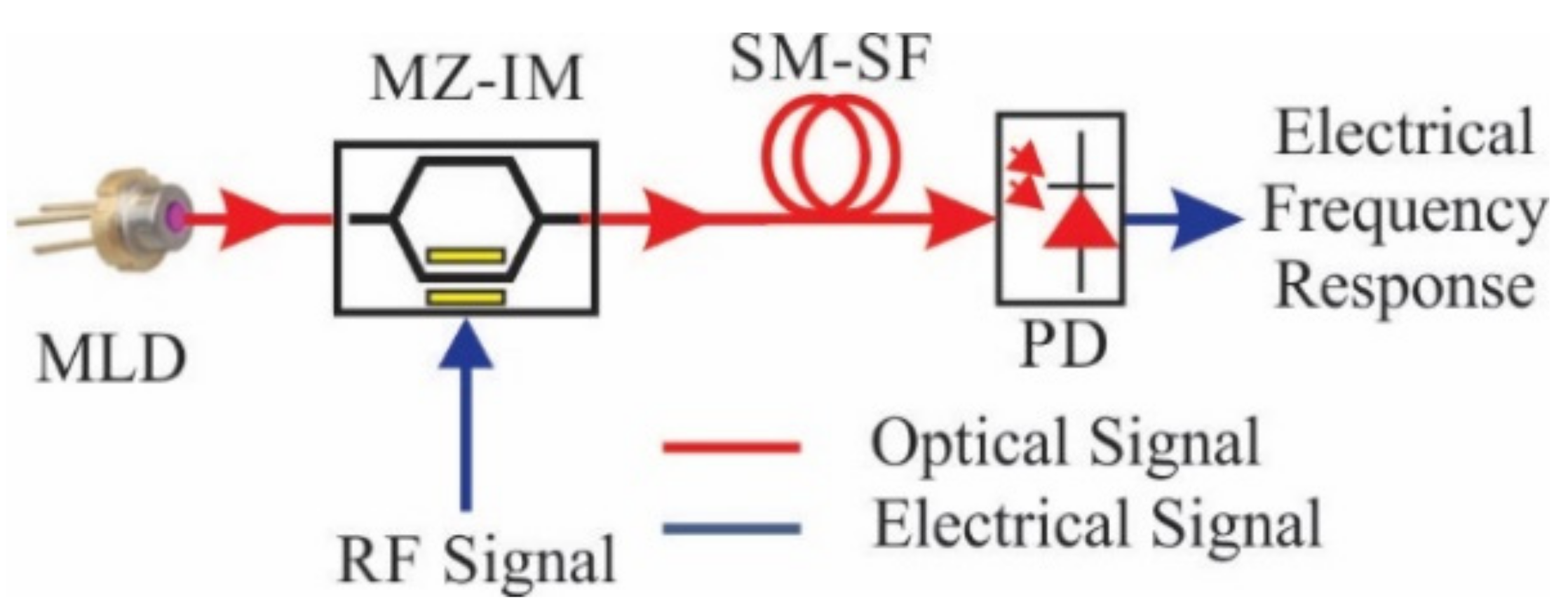
2.2. Principle of Operation of the MPF
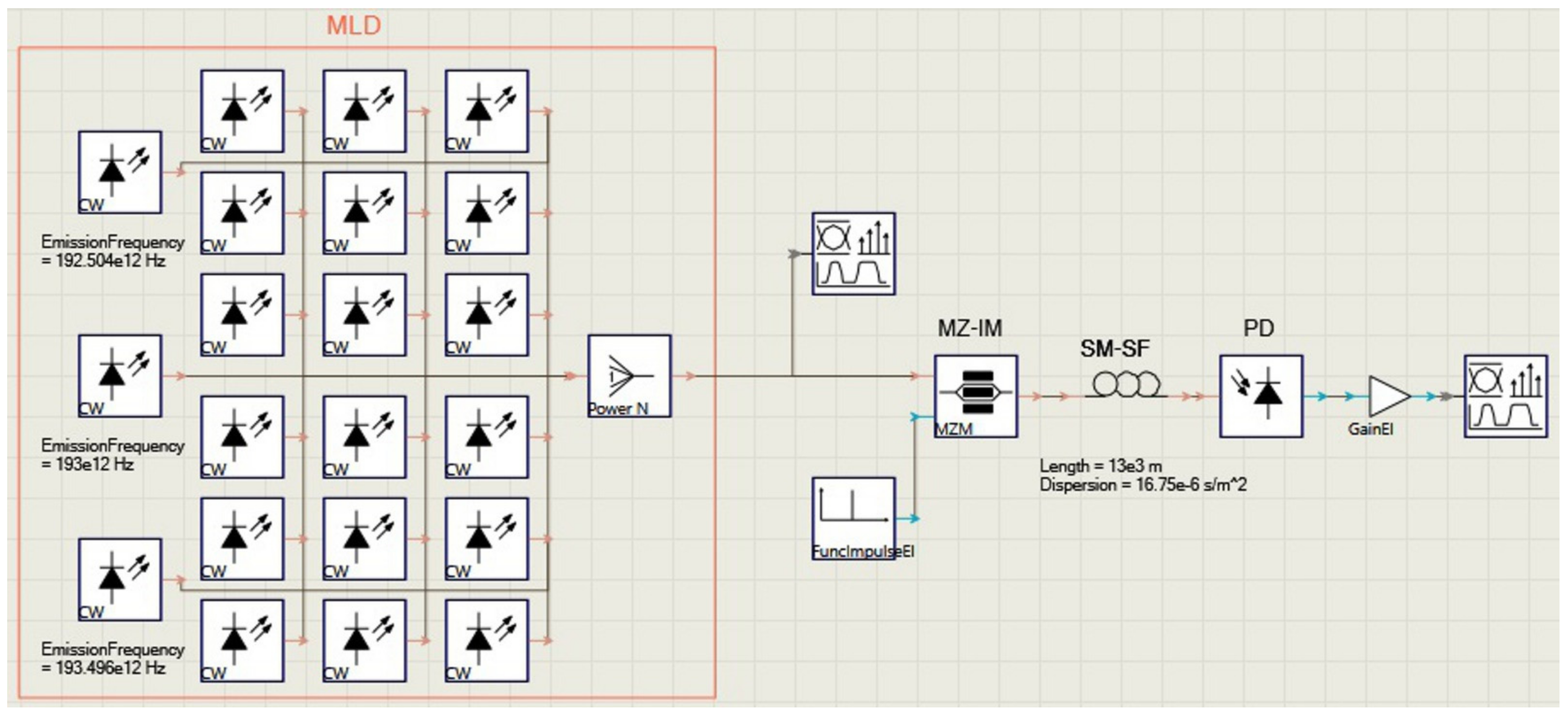
3. Simulation and Results
4. Conclusions
Author Contributions
Funding
Acknowledgments
Conflicts of Interest
References
- Yao, J. Microwave Photonics. J. Lightwave Technol. 2009, 27, 314–335. [Google Scholar] [CrossRef]
- Capmany, J.; Ortega, B.; Pastor, D. A tutorial on microwave photonic filters. J. Lightwave Technol. 2006, 24, 201–229. [Google Scholar] [CrossRef]
- Yao, J. Photonics to the Rescue: A Fresh Look at Microwave Photonic Filters. IEEE Microw. Mag. 2015, 16, 46–60. [Google Scholar] [CrossRef]
- Correa-Mena, A.G.; Vera-Marquina, A.; García-Juárez, A.; Rodríguez-Asomoza, J.; Zaldívar-Huerta, I.E. Experimental Transmission of Digital Data Coded on Electrical Carriers at 2.1 GHz and 4.2 GHz by Using a Microwave Photonic Filter. Electronics 2020, 9, 833. [Google Scholar] [CrossRef]
- Ding, Z.; Zhao, J.; Yang, F.; Feng, Z.; Lu, B.; Cai, H. Wide Bandwidth Reconfigurable and Frequency Tunable Microwave Photonic Filter Based on Tunable Ultra-sharp Roll-off Optical Filter. In Proceedings of the 2018 Asia Communications and Photonics Conference (ACP), Hangzhou, China, 26–29 October 2018; pp. 1–3. [Google Scholar]
- Liu, L.; Jin, X.; Ning, T.; Chen, L.R.; Capmany, J. Optical Spectral Slicing Based Reconfigurable and Tunable Microwave Photonic Filter. J. Lightwave Technol. 2020, 38, 5492–5499. [Google Scholar] [CrossRef]
- Mirza, J.; Atieh, A.; Aljohani, A.J.; Ghafoor, S. Design and optimization of a microwave photonic filter exploiting differential mode group delay of a multi-mode fiber. Opt. Rev. 2021, 28, 199–206. [Google Scholar] [CrossRef]
- Available online: https://www.vpiphotonics.com/index.php (accessed on 13 May 2021).
- Kasap, S.O. Optoelectronics and Photonics: Principles and Practices; Prentice Hall: Hoboken, NJ, USA, 2001. [Google Scholar]
- Venghaus, H. Wavelength Filters in Fibre Optics; Springer Nature: Cham, Switzerland, 2006. [Google Scholar]
- González-Mondragón, L.; Quintero-Rodríguez, L.; García-Juárez, A.; Vera-Marquina, A.; Zaldívar-Huerta, I. Multiple passband microwave photonic filter with adjustable bandwidth. Opt. Laser Technol. 2020, 126, 106133. [Google Scholar] [CrossRef]


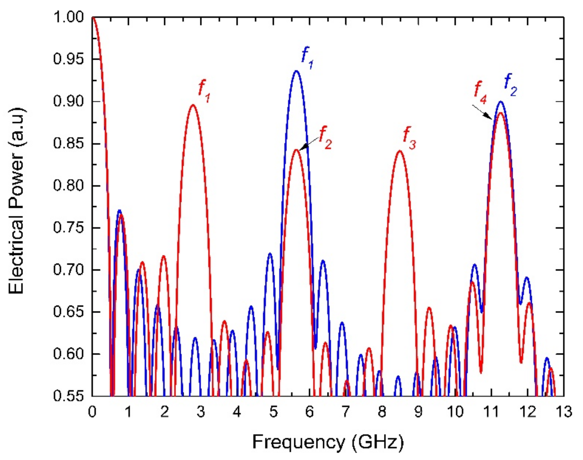
| L = 13 km, D = 16.75 ps/nm⋅km | |||||||
| - | f1 (GHz) | f2 (GHz) | f3 (GHz) | f4 (GHz) | - | - | - |
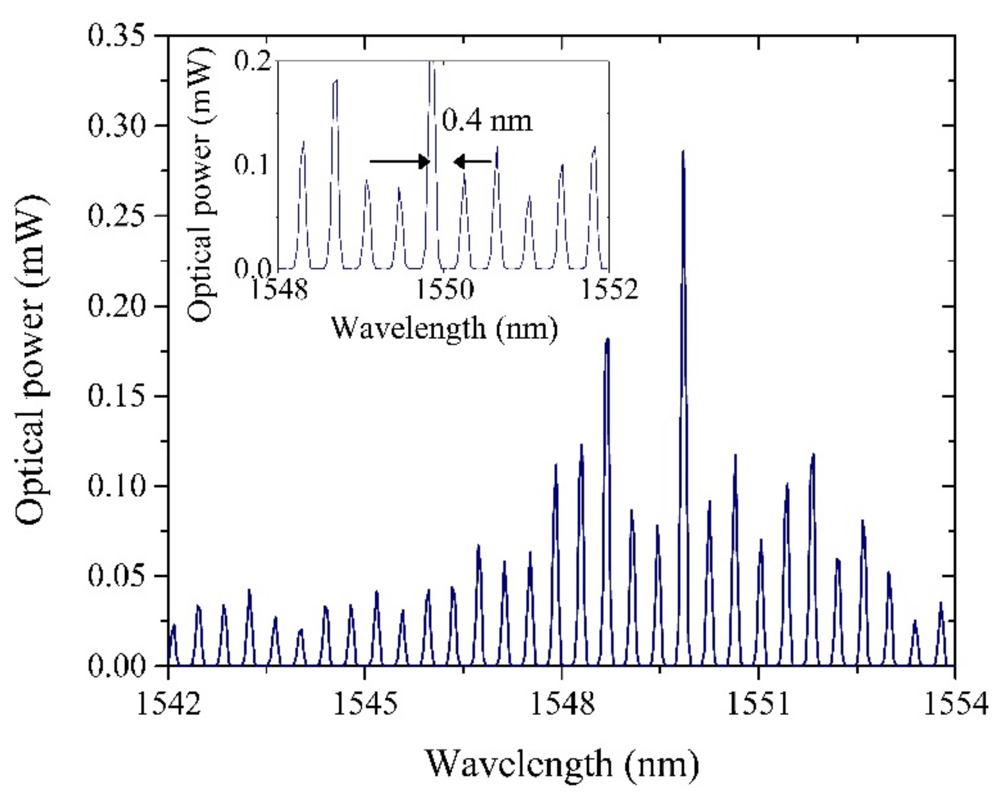
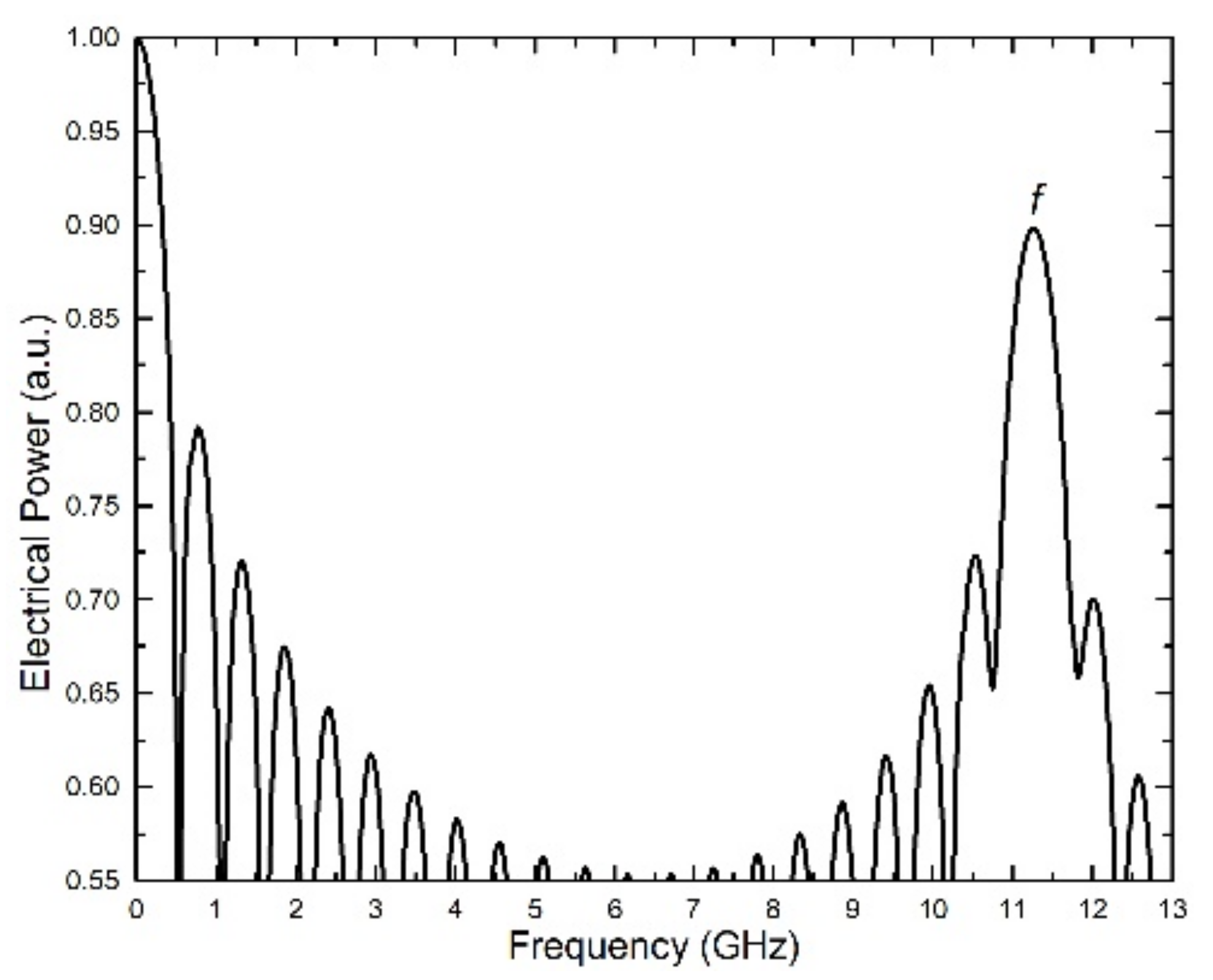
| δλ = 0.40 nm | 11.26 | - | - | - | - | - | - |
| Computed by Equation (2) | 11.48 | - | - | - | - | - | - |
| δλ = 0.82 nm | 5.64 | 11.26 | - | - | - | - | - |
| Computed by Equation (2) | 5.60 | 11.20 | - | - | - | - | - |
| δλ = 1.61 nm | 2.77 | 5.64 | 8.47 | 11.26 | - | - | - |
| Computed by Equation (2) | 2.85 | 5.70 | 8.55 | 11.40 | - | - | - |
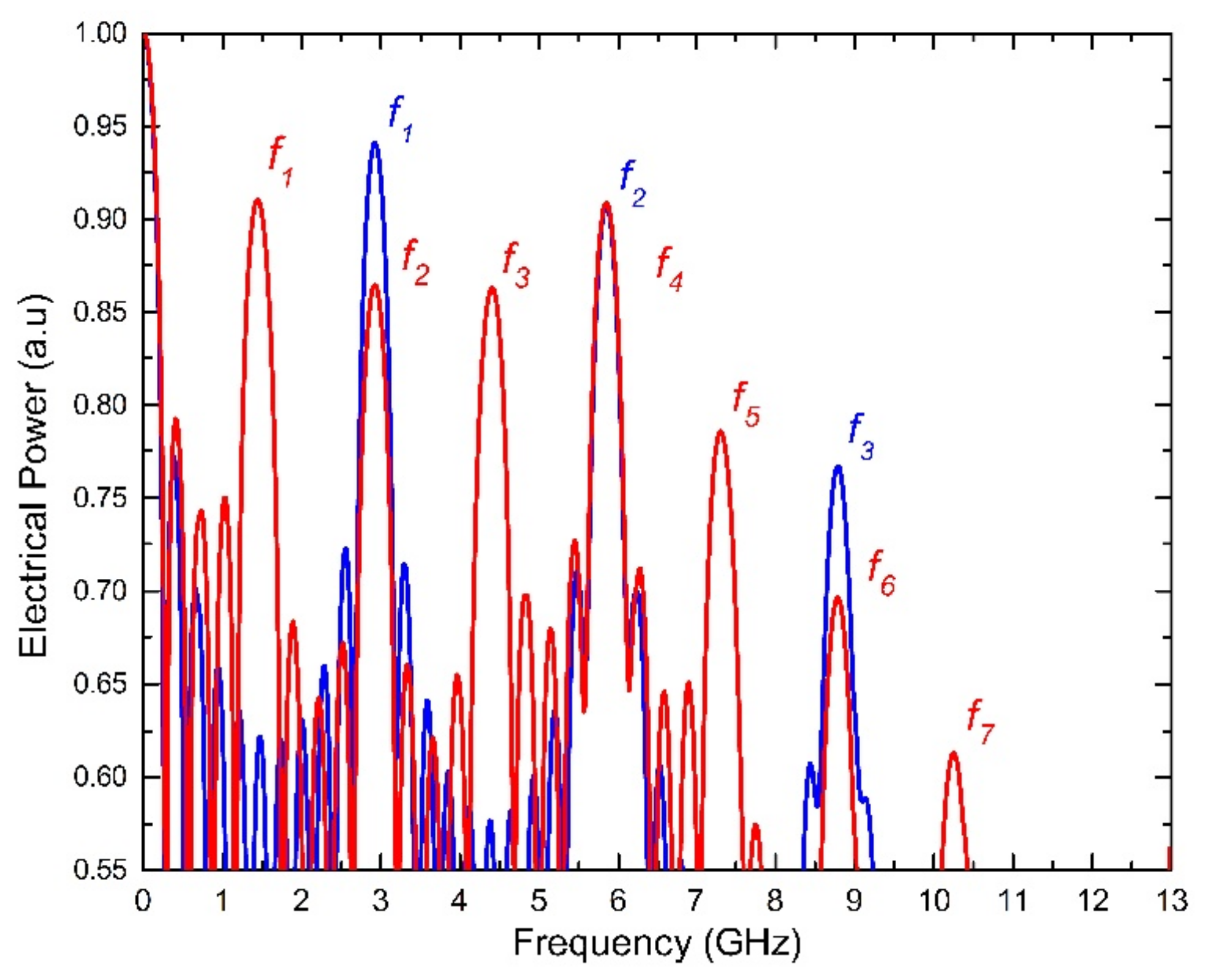
| L = 25 km, D = 16.75 ps/nm⋅km | |||||||
| - | f1 (GHz) | f2 (GHz) | f3 (GHz) | f4 (GHz) | f5 (GHz) | f6 (GHz) | f7 (GHz) |
| δλ = 0.40 nm | 5.95 | - | - | - | - | - | - |
| Computed by Equation (2) | 5.97 | 11.94 | - | - | - | - | - |
| δλ = 0.82 nm | 2.92 | 5.87 | 8.78 | - | - | - | - |
| Computed by Equation (2) | 2.91 | 5.82 | 8.73 | 11.64 | - | - | - |
| δλ = 1.61 nm | 1.44 | 2.92 | 4.41 | 5.87 | 7.30 | 8.78 | 10.25 |
| Computed by Equation (2) | 1.48 | 2.96 | 4.44 | 5.93 | 7.41 | 8.89 | 10.38 |
Publisher’s Note: MDPI stays neutral with regard to jurisdictional claims in published maps and institutional affiliations. |
© 2021 by the authors. Licensee MDPI, Basel, Switzerland. This article is an open access article distributed under the terms and conditions of the Creative Commons Attribution (CC BY) license (https://creativecommons.org/licenses/by/4.0/).
Share and Cite
Tshibangu-Mbuebue, B.; Rojas Laguna, R.; Lee, M.W.; Rodríguez-Asomoza, J.; Zaldívar-Huerta, I.E. Numerical Study of a Reconfigurable Multiband Microwave Photonic Filter Using a Tunable Fabry-Perot Filter. Electronics 2021, 10, 1473. https://doi.org/10.3390/electronics10121473
Tshibangu-Mbuebue B, Rojas Laguna R, Lee MW, Rodríguez-Asomoza J, Zaldívar-Huerta IE. Numerical Study of a Reconfigurable Multiband Microwave Photonic Filter Using a Tunable Fabry-Perot Filter. Electronics. 2021; 10(12):1473. https://doi.org/10.3390/electronics10121473
Chicago/Turabian StyleTshibangu-Mbuebue, Blaise, Roberto Rojas Laguna, Min Won Lee, Jorge Rodríguez-Asomoza, and Ignacio Enrique Zaldívar-Huerta. 2021. "Numerical Study of a Reconfigurable Multiband Microwave Photonic Filter Using a Tunable Fabry-Perot Filter" Electronics 10, no. 12: 1473. https://doi.org/10.3390/electronics10121473
APA StyleTshibangu-Mbuebue, B., Rojas Laguna, R., Lee, M. W., Rodríguez-Asomoza, J., & Zaldívar-Huerta, I. E. (2021). Numerical Study of a Reconfigurable Multiband Microwave Photonic Filter Using a Tunable Fabry-Perot Filter. Electronics, 10(12), 1473. https://doi.org/10.3390/electronics10121473