All articles published by MDPI are made immediately available worldwide under an open access license. No special
permission is required to reuse all or part of the article published by MDPI, including figures and tables. For
articles published under an open access Creative Common CC BY license, any part of the article may be reused without
permission provided that the original article is clearly cited. For more information, please refer to
https://www.mdpi.com/openaccess.
Feature papers represent the most advanced research with significant potential for high impact in the field. A Feature
Paper should be a substantial original Article that involves several techniques or approaches, provides an outlook for
future research directions and describes possible research applications.
Feature papers are submitted upon individual invitation or recommendation by the scientific editors and must receive
positive feedback from the reviewers.
Editor’s Choice articles are based on recommendations by the scientific editors of MDPI journals from around the world.
Editors select a small number of articles recently published in the journal that they believe will be particularly
interesting to readers, or important in the respective research area. The aim is to provide a snapshot of some of the
most exciting work published in the various research areas of the journal.
Maritime safety issues have aroused great attention, and it has become a difficult problem to use the sky-wave over-the-horizon radar system to locate foreign targets or perform emergency rescue quickly and timely. In this paper, a distributed multi-point sky-wave over-the-horizon radar system is used to locate marine targets. A positioning algorithm based on the Doppler frequency is proposed, namely, the two-step weighted least squares (2WLS) method. This algorithm first converts the WGS-48 geodetic coordinates of the transceiver station to spatial rectangular coordinates; then, introduces intermediate variables to convert the nonlinear optimization problem into a linear problem. In the 2WLS method, four mobile transmitters and four mobile receivers are set up, and the Doppler frequency is calculated by transmitting and receiving signals at regular intervals; it is proven that the 2WLS algorithm has always maintained a better positioning accuracy than the WLS algorithm as the error continues to increase with a certain ionospheric height measurement error and the Doppler frequency measurement error. This paper provides an effective method for the sky-wave over-the-horizon radar to locate maritime targets.
The sky-wave over-the-horizon radar (OTHR) uses ionospheric reflection or refraction to realize the propagation of radio waves. It mainly uses shortwave frequency bands, usually 3–30 MHz, and its range can break through the limitations of the curvature of the earth beyond the line-of-sight [1], and the over-the-horizon radar is mainly used for early warning [2]. It has a long detection record and long warning time for aircraft and missiles flying at low altitude. It is an effective means of low-altitude defense.
Meanwhile, the sky-wave over-the-horizon radar system’s ability to locate ship targets in distance and azimuth has also attracted widespread attention [3]. The sky-wave over-the-horizon radar system is positioned to transmit radar signals from the transmitting antenna, which are reflected or refracted by a relatively stable ionosphere; then, they reach the target, and reach the receiving antenna after being scattered by the target to detect the ship target beyond the visible range. The state of the ionosphere determines the positioning performance of the skywave over-the-horizon radar system, and the models describing the ionosphere state are usually divided into the International Reference Ionosphere (IRI) model, the Chapman ionosphere model and the multiple pseudo-parabolic model (MQP) [1]. In this paper, the MQP model is used to describe the OTHR system in which multistatic radar signals travel through the ionosphere. In the OTHR system, the transmitted signal with a specific frequency hits the ship target after being reflected by different ionospheres of different heights. In addition, the signal bounced back from the ship target can also reach the receiver after being reflected by different ionospheres of different heights [4]. These factors lead to multiple propagation paths, which is called the multipath ionospheric propagation (MIP) phenomenon [5].
There are many positioning methods for multistatic radar systems, for example, target positioning based on the combination of the time difference of arrival (TDOA), the frequency difference of arrival (FDOA) and the angle of arrival (AOA). The author of [6] proposes a weighted least squares (WLS) scheme to estimate the target location in the TRM multistatic radar system by considering the measured azimuth angle and the measured elevation angle. An iterative double extended Kalman filter (EKF) algorithm is proposed to locate mobile transmitters by using TDOA and FDOA [7]. However, for moving targets, the Doppler frequency can often be used as an important positioning parameter [8]. The Doppler frequency in [9] is used to locate multiple-input multiple-output (MIMO) radar systems with a wide range of separation stations. The position and speed of the target can be obtained in the Doppler estimation frequency. The author of [10] uses two best linear unbiased estimators (BLUE) based on the measured Doppler frequency to obtain the display solution of the neighboring target position. Based on the highly nonlinear positioning optimization problems obtained by these methods [11], the grid search method is very popular, but it requires a lot of calculation [12]. In [13], after establishing a suitable cost function by using the Doppler frequency measurement, the coverage area is searched grid by grid to find the position of the target in the two-dimensional space. However, there is very little research on target positioning for sky-wave over-the-horizon radar systems. Due to the particularity of the signal propagation path in the ionosphere [14], refraction or reflection will occur, which makes it difficult to locate [15].
In this paper, a signal model of the sky-wave over-the-horizon radar system based on the Doppler frequency measurement is established to obtain a positioning optimization equation, and a two-step weighted least square method (2WLS) is proposed to transform the highly non-linear optimization problem into a linear optimization problem. The simulation shows that the 2WLS algorithm has better positioning accuracy than the WLS algorithm within a certain range of ionospheric height measurement error and the Doppler frequency measurement error.
2. Signal Model
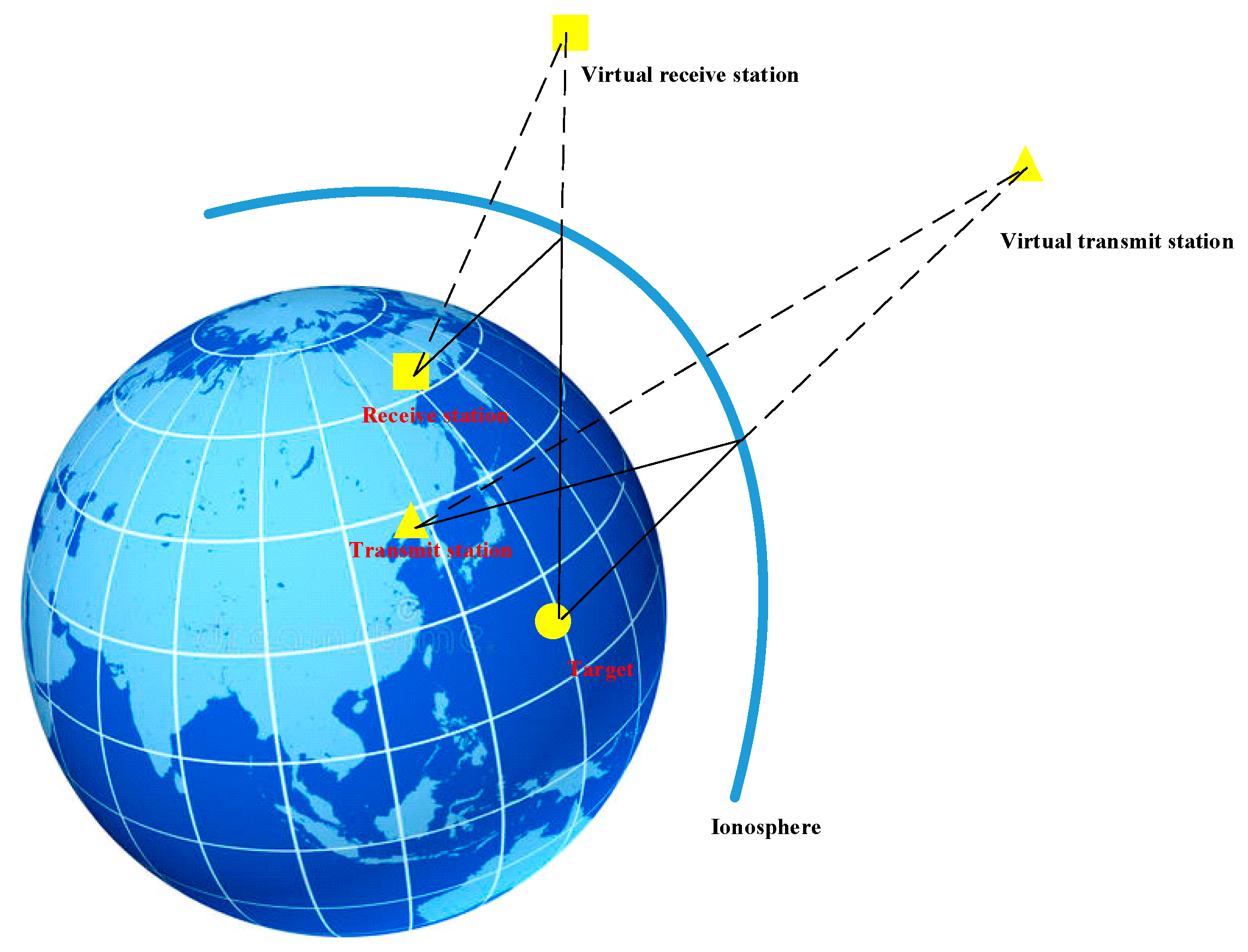
In the OTHR system in this paper, there are transmitters (The transmitter both transmits and receives signals), receivers, and a stationary ship target (when the target is stationary, the receiving station is in motion and the Doppler frequency can be measured). Each transmitter radiates signals of different frequencies to the ionosphere, and reaches the target through ionosphere refraction or reflection, and then each receiver receives the reflection of the target—its propagation model [16] is shown in Figure 1.
In order to further describe the propagation path model, this paper uses an equivalent figure to represent the path propagation [13], as shown in Figure 2. Using the ionosphere as the reflecting surface [17], the transmitting station and the receiving station are mirrored to produce virtual stations [18], which makes the signal propagation route from a broken line to a straight line [19], and it is convenient for the following formula derivation.
Therefore, in this article there are moving receiving stations(The transmitter both transmits and receives signals) and a stationary target, and the moving speed and trajectory of the receiving stations are known. After a short time interval, each receiving station receives the target signal once. It is assumed that each receiving station receives target signal measurements, a total of Doppler measurements can be obtained. The virtual receiver’s position (The position latitude and longitude of the virtual receiver and the real receiver are the same, and the altitude is twice the height of the ionosphere), the speed (The virtual receiver has the same speed as the real receiver) are developed to estimate the target position , then express the observed value of Doppler frequency as
where the original carrier frequency of the signal is , is the propagation speed of the signal, is the measurement error.
The normalized Doppler frequency is written as:
where , , 𝑖 are the index of the receivers. For the sake of simplicity, will be called the Doppler frequency measurement value.
Next, all the measured noise is composed into a vector , which is a Gaussian random variable with zero mean and its covariance matrix is . All measured values form the vector , then the conditional probability density function of the measured value relative to the target position can be expressed as:
where
It can be seen from the above formula that the ML estimation of the target position is obtained through the following optimization problem:
Since the relationship between and is highly non-linear, it is difficult to solve directly. Next, one algorithm is proposed to solve this optimization problem.
3. Two-Step Weighted Least Squares (2WLS)
In many papers, the WLS algorithm is applied to the multistatic radar system positioning, and a good positioning estimation is obtained [20]. Therefore, in this article, the WLS algorithm is applied to the sky-wave over-the-horizon radar system as the initial positioning, and the positioning is determined according to the 2WLS algorithm. Performance is more optimized.
First, both the left and right sides of Equation (2) multiply by , to obtain:
where , represent the distance between the target and the receiving station.
Then, squaring both sides of the equation in Equation (6):
Among them, high-order error terms are omitted [21].
Suppose the target location is ( is the geodetic longitude, is the geodetic latitude, and is the altitude), the signal station is and convert the WGS-84 geodetic coordinate system to a rectangular coordinate system [22]:
where the radius of the earth is , the earth’s major and minor axes are and , is the first eccentricity of earth, and:
Then Equation (7) can be expressed as:
Introducing the unknown vector , Equation (10) can be rewritten in the matrix form as follows:
where:
Applying the WLS to Equation (11) gives the estimation values:
where:
Observing Equation (14), it can be seen that is related to the target position , but is unknown, so in the following simulation, will be processed to obtain the initial WLS estimate of the target position, then substitute the initial estimate to obtain a more accurate solution [23].
According to the Gauss-Markov theorem, when the measurement error is small, is the best unbiased estimate of , and the covariance matrix of is:
where is the estimation error.
Observing , the target position estimation can be obtained from the first three elements of , , but the other elements of also contain the information of :
Using equation (16) and the definition of , to obtain:
Regarding each equation of (17) as a function of the target position , and performing Taylor expansion at , ignoring the error above the second order can be obtained:
Defining the estimated error of the target position , Therefore, regard the left side of the equal sign of each equation in (16) as the measurement equation of , and the right side of the equal sign as the measurement error.
Then, in the joint identity, , and , second linear equation about can be constructed:
where:
Then, obtain the 2WLS estimate of :
Therefore, the final target position is estimated as:
Finally, convert the target position in the Cartesian coordinate system to the geodetic coordinate system [23]:
Then, to obtain the target final position coordinates , but in this paper the ship’s goal is considered, .
4. Simulation Results
In the paper, there are four transmitting stations and four receiving stations, the transmitting station can also receive signals and stations perform a uniform linear motion, so the coordinates and speed of the eight signal stations are set as:
Labels one, two, three and four are transmitting stations, and labels five, six, seven and eight are receiving stations. The initial hypothetical target location is . The detection range of the sky-wave over-the-horizon radar can reach low-altitude or maritime targets of 800 km~2000 km [24], so the minimum detection range in this paper is about 950 km, and the maximum detection range is about 1600 km.
This paper compares the estimation performance of the proposed 2WLS positioning algorithm with the estimation algorithm WLS. Since the positioning performance of the 2WLS algorithm may be affected by the Doppler frequency error proposed in the article or the reflected ionospheric height error [25], this paper is divided into three cases, one is the positioning accuracy simulation based on the Doppler frequency error, the second is the positioning accuracy simulation based on the ionospheric height error [26], and the third is the positioning accuracy simulation based on the Doppler frequency error and the ionospheric height error [27]. In the simulation, all receiving stations perform the Doppler frequency measurement every 5 s, a total of 10 measurements are performed, and then, the algorithm in this paper is used to locate the target. The results in the figure are all obtained through 1000 Monte Carlo simulation experiments.
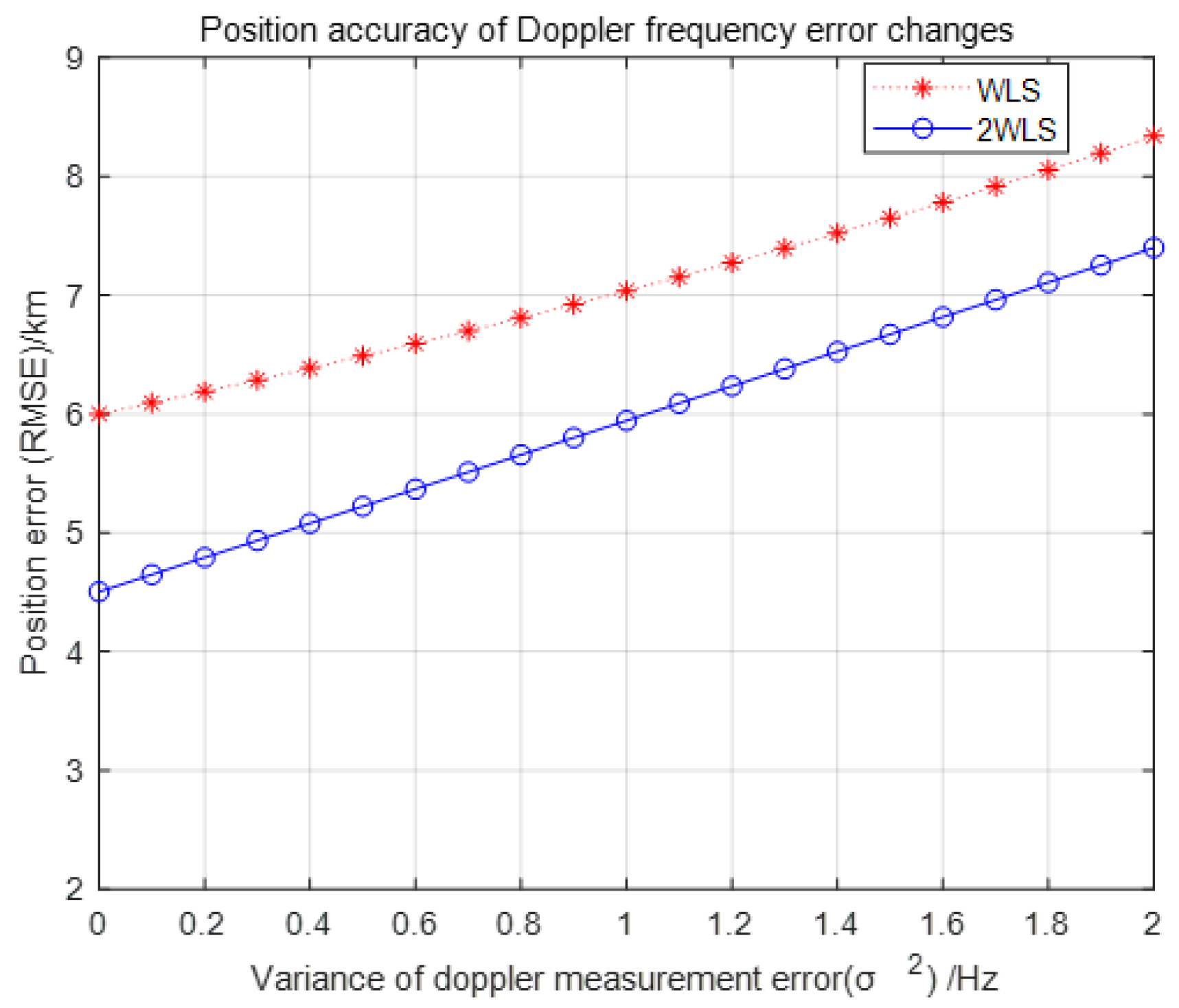
When simulating positioning accuracy based on the Doppler frequency error, assume that the error of each Doppler frequency measurement is an independent and identically distributed Gaussian variable, and its variance is , that is, in the measurement model shown in Equation (3), there are . Under different variance values , compare the positioning accuracy of the above two algorithms. Figure 3 shows the simulation results. are the first four equivalent reflection heights of the ionosphere, and the last equivalent reflection height of the ionosphere are . It can be concluded that compared with the traditional WLS positioning algorithm, the 2WLS positioning algorithm has better positioning performance when only the Doppler frequency error changes.
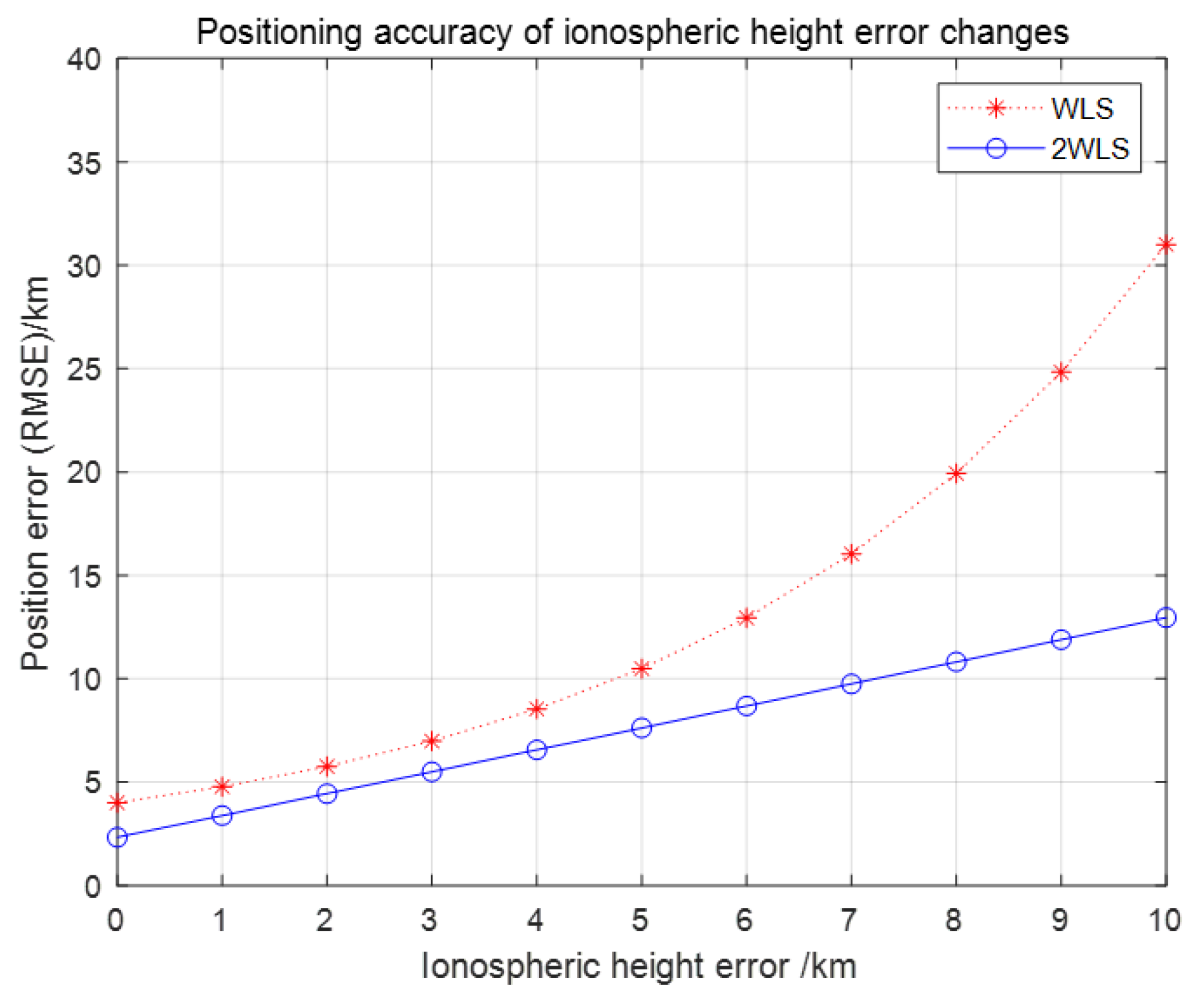
When the positioning accuracy is simulated based on the height error of the reflected ionosphere, the Doppler frequency error is set to 1 Hz, the basic ionospheric reflection height of all transmitting stations and receiving stations is 100 km, and the error range is 0~10 km. The simulation result is shown in Figure 4, and it can be concluded that the error increases with the height of the ionosphere, the positioning accuracy of 2WLS is far better than that of WLS.
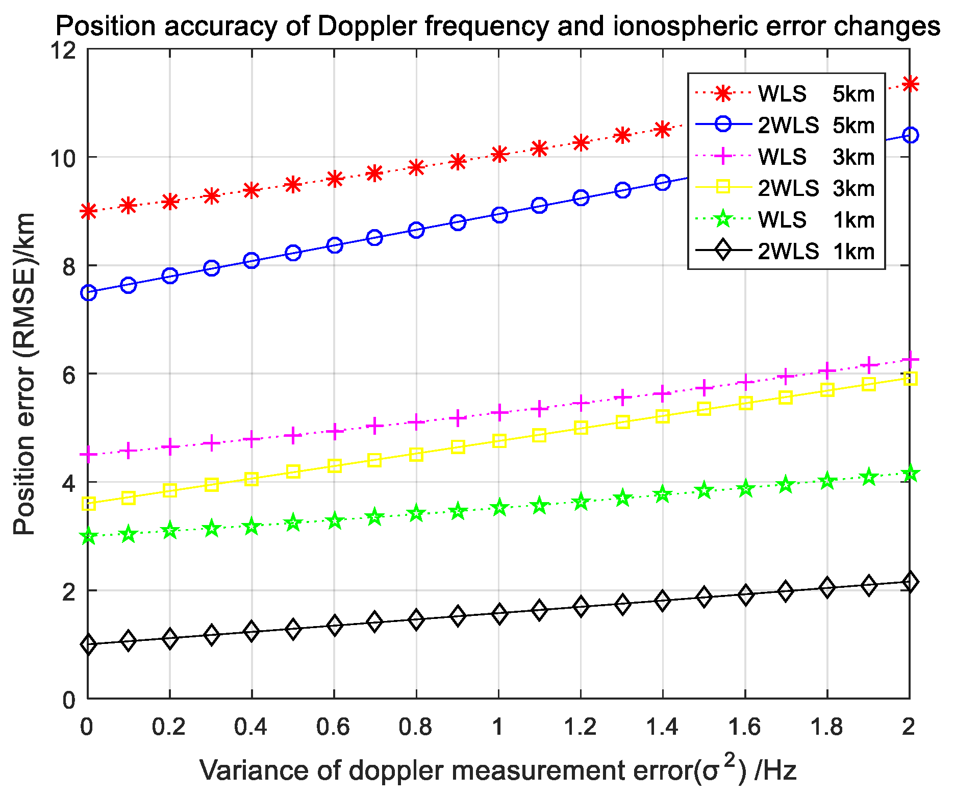
Figure 5 shows the change in positioning accuracy when both the Doppler frequency error and the ionospheric height error change. With the changes of the two, it can be seen from the figure that in the case of the Doppler frequency error, the lower the reflection point of the ionosphere, the better the positioning accuracy. On the contrary, when the ionospheric height error is constant as the Doppler frequency error increases, the positioning accuracy will also deteriorate. When the basic ionospheric reflection height of all transmitting stations and receiving stations is 105 km, compare with the ionospheric random error of 5 km and the ionospheric random errors of 1km and 3 km, the positioning accuracy gap is relatively large, which is also in line with the trend in Figure 5, that as the ionospheric error becomes larger and larger, the positioning accuracy error also shows an approximate exponential increase.
5. Conclusions
In this paper, the signal propagation path was converted from a polygonal line to a straight line by using the principle of specular reflection according to the particularity of the sky-wave over-the-horizon radar signal propagating in the ionosphere; then, the signal model was established to obtain a highly nonlinear positioning optimization problem. The WLS algorithm was adopted to convert the nonlinear optimization problem into a linear optimization problem, which obtains the initial position estimation. The 2WLS algorithm is proposed to further optimize the positioning accuracy. It can be obtained that the 2WLS algorithm has better positioning accuracy than the WLS algorithm through simulation within a certain range of the Doppler frequency measurement error and ionospheric height measurement error.
Although the 2WLS algorithm proposed in this paper has enriched the positioning estimation algorithm for marine ship targets in the sky-wave over-the-horizon radar system to a certain extent, it still needs further research in some aspects. In the future, the sky-wave over-the-horizon radar could locate multiple targets on maritime ships and use more advanced algorithms to combine with the algorithms in this article, such as the convex optimization algorithm and particle swarm optimization (PSO), to improve the accuracy of the algorithm and the validity of the conclusions.
Author Contributions
F.R. and H.G. conceived and designed the experiments; F.R. and L.Y. performed the experiments; L.Y. and F.R. analyzed the data; F.R. contributed reagents/materials/analysis tools; and F.R. and H.G. wrote the paper. All authors have read and agreed to the published version of the manuscript.
Funding
This research was funded by the National Natural Science Foundation of China (No.61671333), the Natural Science Foundation of Hubei Province (No.2014CFA093), the Fundamental Research Funds for the Central Universities (No.2042019K50264, No.2042019GF0013 and 2042020gf0003) and the Fundamental Research Funds for the Wuhan Maritime Communication Research Institute (No. 2017J-13).
Conflicts of Interest
The authors declare no conflict of interest.
References
Mostafa Nazari, M.; Mohseni, R. Waveform Design with Application in Over-The-Horizon skywave Radar. Shiyou Kantan Yu Kaifa/Pet. Explor. Dev.2015, 42, 507–511. [Google Scholar]
Kingsley, S.; Quegan, S. Over-The-Horizon Radar; Understanding Radar Systems; SciTech Publishing, Inc.: Mendham, CA, USA, 1999. [Google Scholar]
Jiang, P.F.; Chen, J.W.; Bao, Z.; Zhao, Z.G. An Improving Algorithm for Maneuvering Target Altitude Estimation with Skywave Over-The-Horizon Radar. In Proceedings of the 2012 IEEE 11th International Conference on Signal Processing (ICSP), Beijing, China, 21–25 October 2012. [Google Scholar]
Huiyong, L.I.; Xue, C.; Chen, Z.; Jinfeng, H.U.; Yao, F. Maneuvering Target Detection Algorithm Based on Hankel Matrix Decomposition in Over-the-horizon Radar. Dianzi Yu Xinxi Xuebao/J. Electron. Inf. Technol.2018, 40, 541–547. [Google Scholar]
Solomentsev, D.V.; Khattatov, B.V.; Codrescu, M.V.; Titov, A.A.; Yudin, V.; Khattatov, V.U. Ionosphere State and parameter estimation using the Ensemble Square Root Filter and the global three-dimensional first-principle model. Space Weather. Int. J. Res. Appl.2012, 10. [Google Scholar] [CrossRef]
Wen, J.H.; Li, J.S.; Yang, C.Y.; Chen, C.H.; Chen, H.C. Localization Scheme of Multistatic Radars System Based on the Information of Measured Signal. In Proceedings of the 2014 Ninth International Conference on Broadband and Wireless Computing, Communication and Applications, Guangdong, China, 8–10 November 2014. [Google Scholar]
Lee, K.; Oh, J.; You, K. TDOA/FDOA based Adaptive Active Target Localization using Iterated Dual-EKF Algorithm. IEEE Commun. Lett.2019, 4, 752–755. [Google Scholar] [CrossRef]
Wang, D.; Yin, J.; Liu, R.; Yu, H.; Wang, Y. Performance analysis and improvement of direct position determination based on Doppler frequency shifts in presence of model errors: Case of known waveforms. Multidimens. Syst. Signal Process.2019, 30, 749–790. [Google Scholar] [CrossRef]
Kalkan, Y.; Baykal, B. Frequency-based target localization methods for widely separated MIMO radar. Radio Sci.2014, 49, 53–67. [Google Scholar] [CrossRef]
Li, J.D.; Ping, W.; Yan, S.D.; Wan, C.L.; Hong, S.L. An Effective and Simple Solution for Stationary Target Localization Using Doppler Frequency Shift Measurements. IEICE Trans. Fundam. Electron. Commun. Comput. Sci.2017, 100, 1070–1073. [Google Scholar]
Wang, Y.L.; Wu, Y.; Yi, S.C. An efficient direct position determination algorithm combined with time delay and doppler. Circuits Syst. Signal Process.2016, 35, 1–15. [Google Scholar] [CrossRef]
Tirer, T.; Weiss, A.J. High resolution localization of narrowband radio emitters based on Doppler frequency shifts. Signal Process.2017, 141, 288–298. [Google Scholar] [CrossRef]
Kalkan, Y.; Baykal, B. Target localization and velocity estimation methods for frequency-only MIMO Radars. In Proceedings of the 2011 IEEE RadarCon (RADAR), Kansas City, MO, USA, 23–27 May 2011. [Google Scholar] [CrossRef]
Chengyu, H.; Yuxin, W.; Jiawei, C. Estimating Target Heights Based on the Earth Curvature Model and Micromultipath Effect in Skywave OTH Radar. J. Appl. Math.2014, 2014, 1–14. [Google Scholar] [CrossRef]
He, Q.; Blum, R.S.; Haimovich, A.M. Noncoherent MIMO radar for location and velocity estimation: More antennas means better performance. IEEE Trans. Signal Process.2010, 58, 3661–3680. [Google Scholar] [CrossRef]
Yang, L.; Gao, H.; Ling, Y.; Li, B. Localization Method of Wide-Area Distribution Multistatic Sky-Wave Over-the-Horizon Radar. IEEE Geosci. Remote. Sens. Lett.2020, 99, 1–5. [Google Scholar] [CrossRef]
Kalkan, Y.; Baykal, B. Multiple target localization & data association for frequency-only widely separated MIMO radar. Digit. Signal Process.2014, 25, 51–61. [Google Scholar]
Congfeng, L.; Jinwei, Y.; Juan, S. Direct solution for fixed source location using well-posed TDOA and FDOA measurements. J. Syst. Eng. Electron.2020, 31, 666–673. [Google Scholar] [CrossRef]
Zhang, J.; Jin, T.; Qiu, L. Performance analysis for T-RN multistatic radar system. In Proceedings of the 2016 IEEE International Geoscience and Remote Sensing Symposium (IGARSS), Beijing, China, 10–15 July 2016. [Google Scholar]
Du, Y.S.; Wei, P.; Li, W.C.; Liao, H.S. Doppler Shift Based Target Localization Using Semidefinite Relaxation. Ieice Trans. Fundam. Electron. Commun. Comput. Sci.2014, 97, 397–400. [Google Scholar] [CrossRef]
Gao, L.P.; Sun, H.; Liu, M.N.; Jiang, Y.L. TDOA collaborative localization algorithm based on PSO and Newton iteration in WGS-84 coordinate system. In Proceedings of the 2016 IEEE 13th International Conference on Signal Processing (ICSP), Chengdu, China, 6–10 November 2016. [Google Scholar] [CrossRef]
Deng, L.; Wei, P.; Zhang, Z.; Zhang, H. Doppler Frequency Shift Based Source Localization in Presence of Sensor Location Errors. IEEE Access2018, 6, 59752–59760. [Google Scholar] [CrossRef]
Ataş, P.K.; Tufan, K.; Şevkli, A.Z. A variable neighborhood search based feature selection model for early prediction of the Alzhemier’s disease. In Proceedings of the 2016 Electric Electronics, Computer Science, Biomedical Engineerings Meeting (EBBT), Istanbul, Turkey, 26–27 April 2016. [Google Scholar] [CrossRef]
He, Q.; Li, X.; He, Z.; Blum, R.S. MIMO-OTH Radar: Signal Model for Arbitrary Placement and Signals with Non-Point Targets. IEEE Trans. Signal Process.2015, 63, 1846–1857. [Google Scholar] [CrossRef]
Tzafri, L.; Weiss, A.J. High-resolution direct position determination using MVDR. IEEE Trans. Wirel. Commun.2016, 15, 6449–6461. [Google Scholar] [CrossRef]
Luo, Z.; He, Z.; Chen, X.; Lu, K. Target location and height estimation via multipath signal and 2D array for sky-wave over-the-horizon radar. IEEE Trans. Aerosp. Electron. Syst.2016, 52, 617–631. [Google Scholar] [CrossRef]
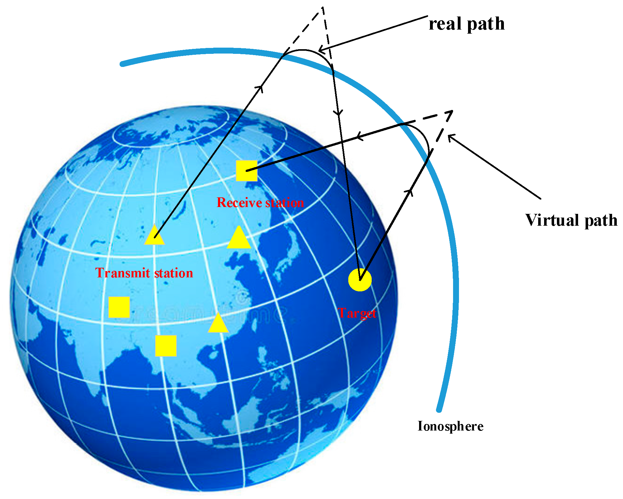
Figure 1.
The propagation path of the signal after reflection from the ionosphere. The virtual path is equivalent to the propagation in the air. The true path is curved due to the reflection of the ionosphere.
Figure 1.
The propagation path of the signal after reflection from the ionosphere. The virtual path is equivalent to the propagation in the air. The true path is curved due to the reflection of the ionosphere.
Figure 2.
Virtual sensor equivalent diagram.
Figure 2.
Virtual sensor equivalent diagram.
Figure 3.
The relationship between the Doppler frequency error and positioning accuracy.
Figure 3.
The relationship between the Doppler frequency error and positioning accuracy.
Figure 4.
The relationship between the reflected ionospheric height error and positioning accuracy.
Figure 4.
The relationship between the reflected ionospheric height error and positioning accuracy.
Figure 5.
The relationship between the Doppler frequency error, ionospheric height error and positioning accuracy.
Figure 5.
The relationship between the Doppler frequency error, ionospheric height error and positioning accuracy.
Publisher’s Note: MDPI stays neutral with regard to jurisdictional claims in published maps and institutional affiliations.
Ren, F.; Gao, H.; Yang, L.
Distributed Multistatic Sky-Wave Over-The-Horizon Radar Based on the Doppler Frequency for Marine Target Positioning. Electronics2021, 10, 1472.
https://doi.org/10.3390/electronics10121472
AMA Style
Ren F, Gao H, Yang L.
Distributed Multistatic Sky-Wave Over-The-Horizon Radar Based on the Doppler Frequency for Marine Target Positioning. Electronics. 2021; 10(12):1472.
https://doi.org/10.3390/electronics10121472
Chicago/Turabian Style
Ren, Fangyu, Huotao Gao, and Lijuan Yang.
2021. "Distributed Multistatic Sky-Wave Over-The-Horizon Radar Based on the Doppler Frequency for Marine Target Positioning" Electronics 10, no. 12: 1472.
https://doi.org/10.3390/electronics10121472
APA Style
Ren, F., Gao, H., & Yang, L.
(2021). Distributed Multistatic Sky-Wave Over-The-Horizon Radar Based on the Doppler Frequency for Marine Target Positioning. Electronics, 10(12), 1472.
https://doi.org/10.3390/electronics10121472
Note that from the first issue of 2016, this journal uses article numbers instead of page numbers. See further details here.
Article Metrics
No
No
Article Access Statistics
For more information on the journal statistics, click here.
Multiple requests from the same IP address are counted as one view.
Ren, F.; Gao, H.; Yang, L.
Distributed Multistatic Sky-Wave Over-The-Horizon Radar Based on the Doppler Frequency for Marine Target Positioning. Electronics2021, 10, 1472.
https://doi.org/10.3390/electronics10121472
AMA Style
Ren F, Gao H, Yang L.
Distributed Multistatic Sky-Wave Over-The-Horizon Radar Based on the Doppler Frequency for Marine Target Positioning. Electronics. 2021; 10(12):1472.
https://doi.org/10.3390/electronics10121472
Chicago/Turabian Style
Ren, Fangyu, Huotao Gao, and Lijuan Yang.
2021. "Distributed Multistatic Sky-Wave Over-The-Horizon Radar Based on the Doppler Frequency for Marine Target Positioning" Electronics 10, no. 12: 1472.
https://doi.org/10.3390/electronics10121472
APA Style
Ren, F., Gao, H., & Yang, L.
(2021). Distributed Multistatic Sky-Wave Over-The-Horizon Radar Based on the Doppler Frequency for Marine Target Positioning. Electronics, 10(12), 1472.
https://doi.org/10.3390/electronics10121472
Note that from the first issue of 2016, this journal uses article numbers instead of page numbers. See further details here.

