
Development of a Simple Robotic Driver System (SimRoDS) to Test Fuel Economy of Hybrid Electric and Plug-In Hybrid Electric Vehicles Using Fuzzy-PI Control


Abstract
1. Introduction
- The CAN (controller area network) signal-operated robot driver system is proposed for accurate and reproducible fuel efficiency tests with easier installation and less cost replacing the physical robot driver system.
- Powered by a simple dynamic PI gain autotuning algorithm based on fuzzy logic, the proposed robot driver system demonstrates much improved target velocity following performance compared to fixed PI gain approach, enabling accurate fuel efficiency testing including industry standards such as the FTP cycle.
2. Problem Description
- When several time-consuming tests, such as distance to empty (DTE), are conducted, it can result in large variations.
- Training professional drivers are costly.
- Robot drivers require a relatively long installation time, and after installation, depending on the vehicle pedal position, an additional calibration process may be necessary.
- Robot drivers are expensive.
- Because robot drivers physically occupy the driver’s seat, vehicle with robot drivers cannot be tested on actual roads.
3. Proposed Robot Driver System Configuration
3.1. Hardware Configuration
3.2. Software Configuration
- Gain autotuner that runs on a Windows-based PC.
- The PI controller that controls the test vehicle.
- Creates a gain value using fuzzy logic and send this value to the controller via TCP/IP communication.
- Shows the status (on, off, malfunction) of the robot driver.
- Visualizes the vehicle CAN signals (velocity, APS, BPS).
- Receives the gain values from the PC and applies them to the PI controller.
- Sends the vehicle and control status to the PC.
4. Method
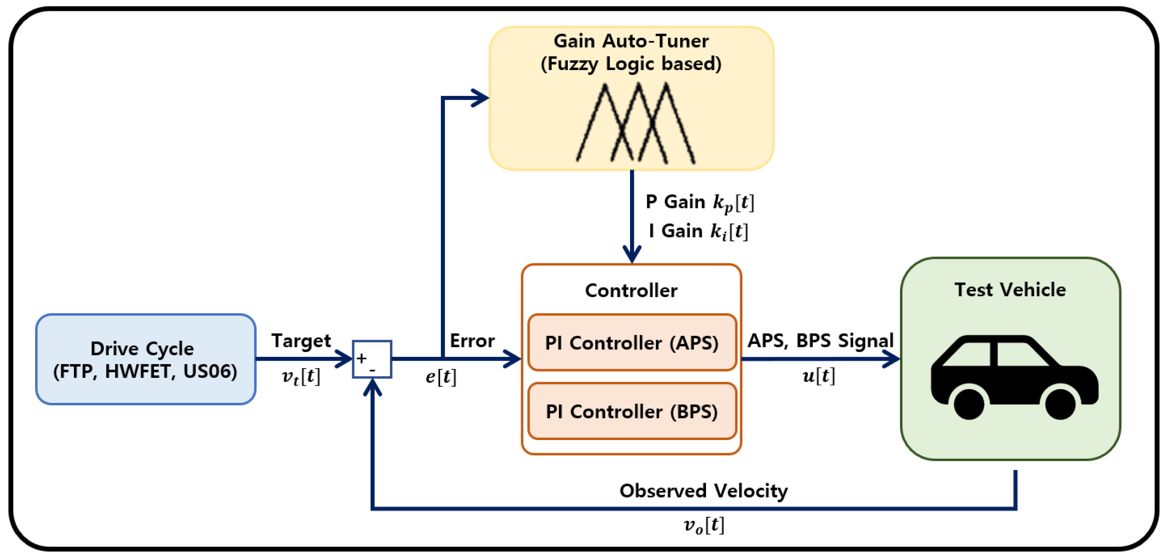
4.1. PI Controller
4.2. Fuzzy Logic
- The mathematical model of the vehicle to be controlled is not required.
- The control output is generated by membership functions when a defined variable is given.
- The inference is developed through a rules table of query and decision
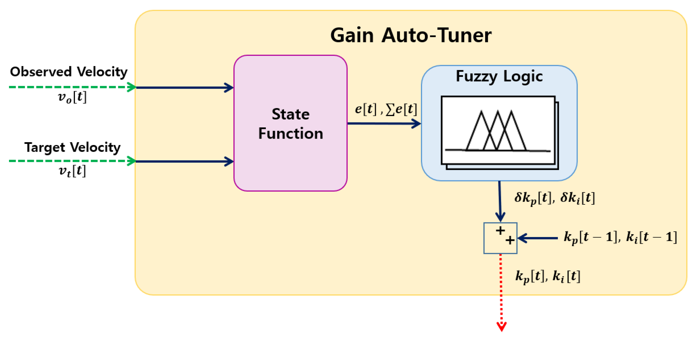
4.3. Fuzzy-Logic-Based Autotuning
- Before the test, the default gain value is defined.
- When the test is initiated, the current error is given to the fuzzy logic.
- With the given error, the change rate of PI gain is calculated.
- The default gain is totaled using the change rate of the gain value (Equation (1)).
- The new gain value is sent to the PI controller via TCP/IP and replaces the default gain value.
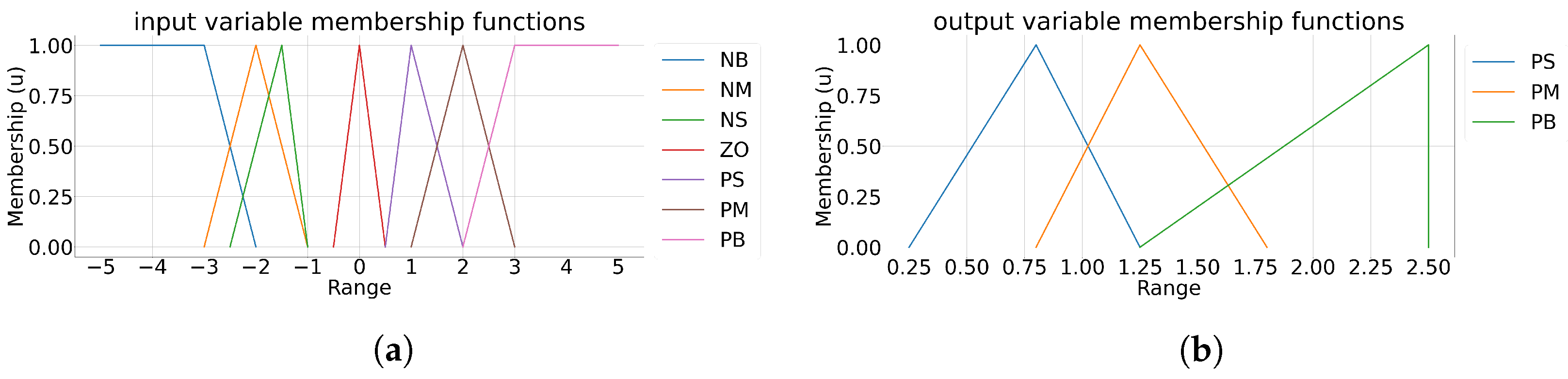
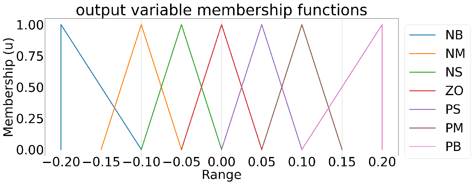
4.3.1. Fuzzy Membership Function
4.3.2. Fuzzy Proportional Controller
4.3.3. Fuzzy Integral Controller
5. Experiment
5.1. Experiment Result with Fixed Gain
5.2. Experiment Result with Dynamic Gain
6. Conclusions and Future Work
Author Contributions
Funding
Conflicts of Interest
Abbreviations
| EV | Electric Vehicle |
| HEV | Hybrid Electric Vehicle |
| PHEV | Plug-in Hybrid Electric Vehicle |
| DHTs | Dedicated Hybrid Transmissions |
| ICE | Internal Combustion Engine |
| APS | Acceleration Position Signal |
| BPS | Brake Position Signal |
| PC | Personal Computer |
| CAN | Controller Area Network |
| DTE | Distance To Empty |
| NEDC | New European Driving Cycle |
| WLTP | Worldwide Harmonized Light Vehicle Test Procedure |
| FTP | Federal Test Procedure |
| UDDS | Urban Dynamometer Driving Schedule |
| TCP/IP | Transmission Control Protocol/Internet Protocol |
| MIMO | Multiple Input and Multiple Output |
| PID | Proportional Integral Derivative |
| RMSE | Root Mean Squared Error |
References
- Sieg, C.; Küçükay, F. Benchmarking of Dedicated Hybrid Transmissions. Vehicles 2020, 2, 100–125. [Google Scholar] [CrossRef]
- Al-Samari, A. Study of emissions and fuel economy for parallel hybrid versus conventional vehicles on real world and standard driving cycles. Alex. Eng. J. 2017, 56, 721–726. [Google Scholar] [CrossRef]
- Kuhnert, F.; Stürmer, C.; Koster, A. Five Trends Transforming the Automotive Industry; PricewaterhouseCoopers GmbH Wirtschaftsprüfungsgesellschaft: Berlin, Germany, 2018; Volume 1, pp. 1–48. [Google Scholar]
- Preeti Wadhwani, P.S. Fuel Cell Electric Vehicle (FCEV) Market Size by Vehicle (Heavy Duty Vehicles, Agriculture, Buses, Port Vehicles/Container Handling or Transport, Automotive, Class 8/Long Haul), by Distance (Short, Long), Industry Analysis Report, Regional Outlook, Growth Potential, Price Trends, Competitive Market Share & Forecast, 2020–2026; Global Market Insights Inc.: Selbyville, DE, USA, 2019; pp. 1–235. [Google Scholar]
- Namik, H.; Inamura, T.; Stol, K. Development of a robotic driver for vehicle dynamometer testing. In Proceedings of the 2006 Australasian Conference on Robotics and Automation, Auckland, New Zealand, 6–8 December 2006; pp. 1–9. [Google Scholar]
- Sailer, S.; Buchholz, M.; Dietmayer, K. Flatness based velocity tracking control of a vehicle on a roller dynamometer using a robotic driver. In Proceedings of the 2011 50th IEEE Conference on Decision and Control and European Control Conference, Orlando, FL, USA, 12–15 December 2011; pp. 7962–7967. [Google Scholar]
- Muller, K.; Leonhard, W. Computer control of a robotic driver for emission tests. In Proceedings of the 1992 International Conference on Industrial Electronics, Control, Instrumentation, and Automation, San Diego, CA, USA, 9–13 November 1992; Volume 3, pp. 1506–1511. [Google Scholar]
- Sailer, S.; Buchholz, M.; Dietmayer, K. Driveaway and braking control of vehicles with manual transmission using a robotic driver. In Proceedings of the 2013 IEEE International Conference on Control Applications (CCA), Hyderabad, India, 28–30 August 2013; pp. 235–240. [Google Scholar]
- Chen, G.; Zhang, W.G.; Zhang, X.N. Speed tracking control of a vehicle robot driver system using multiple sliding surface control schemes. Int. J. Adv. Robot. Syst. 2013, 10, 90. [Google Scholar] [CrossRef]
- Chen, G.; Zhang, W.G.; Zhang, X.N. Fuzzy neural control for unmanned robot applied to automotive test. Int. J. Robot. Res. Appl. 2013, 40, 450–461. [Google Scholar] [CrossRef]
- Eriksson, L.; Norrlöf, M. Improved Drive Cycle Following with an ILC Supported Driver Model. IFAC-PapersOnLine 2015, 48, 347–353. [Google Scholar] [CrossRef]
- Mizutani, N.; Ishida, Y.; Matsui, H.; Yano, K.; Takahashi, T. Automatic driving control by robotic driver considering the lack of a driving force at changing gears. In Proceedings of the 2016 IEEE/RSJ International Conference on Intelligent Robots and Systems (IROS), Daejeon, Korea, 9–14 October 2016; pp. 3075–3080. [Google Scholar]
- Chen, G.; Zhang, W.; Li, X.; Yu, B. Adaptive speed control method for electromagnetic direct drive vehicle robot driver based on fuzzy logic. Meas. Control. 2019, 52, 1344–1353. [Google Scholar] [CrossRef]
- Tjokro, S.; Shah, S.L. Adaptive PID Control. In Proceedings of the 1985 American Control Conference, Boston, MA, USA, 19–21 June 1985; pp. 1528–1534. [Google Scholar]
- Soyguder, S.; Karakose, M.; Alli, H. Design and simulation of self-tuning PID-type fuzzy adaptive control for an expert HVAC system. Expert Syst. Appl. 2009, 36, 4566–4573. [Google Scholar] [CrossRef]
- Khodayari, M.H. Modeling and control of autonomous underwater vehicle (AUV) in heading and depth attitude via self-adaptive fuzzy PID controller. J. Mar. Sci. Technol. 2015, 20, 559–578. [Google Scholar] [CrossRef]
- Kandiban, R.; Arulmozhiyal, R. Speed Control of BLDC Motor Using Adaptive Fuzzy PID Controller. Procedia Eng. 2012, 38, 306–313. [Google Scholar] [CrossRef]
- Xie, D.; Zhu, J.; Wang, F. Fuzzy PID Control To Feed Servo System of CNC Machine Tool. Procedia Eng. 2012, 29, 2853–2858. [Google Scholar]
- Ahmed, S.F.; Kushsairy, K.; Bakar, M.I.A.; Hazry, D.; Joyo, M.K. Attitude stabilization of Quad-rotor (UAV) system using Fuzzy PID controller (an experimental test). In Proceedings of the 2015 Second International Conference on Computing Technology and Information Management (ICCTIM), Johor, Malaysia, 21–23 April 2015; pp. 99–104. [Google Scholar]
- Khan, L.; Qamar, S.; Khan, U. Adaptive PID control scheme for full car suspension control. J. Chin. Inst. Eng. 2016, 39, 169–185. [Google Scholar] [CrossRef]
- Pan, S.; Zhou, H. An adaptive fuzzy PID control strategy for vehicle yaw stability. In Proceedings of the 2017 IEEE 2nd Information Technology, Networking, Electronic and Automation Control Conference (ITNEC), Chengdu, China, 15–17 December 2017; pp. 642–646. [Google Scholar]
- Xu, S.-W.; Lu, J.; Zhao, X. The Driving Control Strategy of Pure Electric Vehicle Based on Fuzzy Self-adaptive PID. In Proceedings of the 2016 4th International Conference on Machinery, Materials and Computing Technology, Hangzhou, China, 23–24 January 2016; Atlantis Press: Dordrecht, The Netherlands, 2016; pp. 940–946. [Google Scholar]
- Eckert, J.J.; de Alkmin Silva, L.C.; Dedini, F.G.; Corrêa, F.C. Electric vehicle powertrain and fuzzy control multi-objective optimization, considering dual hybrid energy storage systems. IEEE Trans. Veh. Technol. 2020, 69, 3773–3782. [Google Scholar] [CrossRef]
- Nguyen, A.T.; Rath, J.; Guerra, T.M.; Palhares, R.; Zhang, H. Robust set-invariance based fuzzy output tracking control for vehicle autonomous driving under uncertain lateral forces and steering constraints. In Proceedings of the 2020 IEEE International Conference on Fuzzy Systems (FUZZ-IEEE), Glasgow, UK, 19–24 July 2020; pp. 1–12. [Google Scholar]
- Min, X.; Li, Y.; Tong, S. Adaptive fuzzy output feedback inverse optimal control for vehicle active suspension systems. Neurocomputing 2020, 403, 257–267. [Google Scholar] [CrossRef]
- Nazemian, H.; Masih-Tehrani, M. Hybrid Fuzzy-PID Control Development for a Truck Air Suspension System. SAE Int. J. Commer. Veh. 2020, 13, 55–70. [Google Scholar] [CrossRef]
- Eze, E.C.; Zhang, S.; Liu, E. Vehicular ad hoc networks (VANETs): Current state, challenges, potentials and way forward. In Proceedings of the 2014 20th International Conference on Automation and Computing, Cranfield, UK, 12–13 September 2014; pp. 176–181. [Google Scholar]
- Lin, Y.; McPhee, J.; Azad, N.L. Comparison of deep reinforcement learning and model predictive control for adaptive cruise control. IEEE Trans. Intell. Veh. 2020, 6, 221–231. [Google Scholar] [CrossRef]


Publisher’s Note: MDPI stays neutral with regard to jurisdictional claims in published maps and institutional affiliations. |
© 2021 by the authors. Licensee MDPI, Basel, Switzerland. This article is an open access article distributed under the terms and conditions of the Creative Commons Attribution (CC BY) license (https://creativecommons.org/licenses/by/4.0/).
Share and Cite
Hwang, K.; Park, J.; Kim, H.; Kuc, T.-Y.; Lim, S. Development of a Simple Robotic Driver System (SimRoDS) to Test Fuel Economy of Hybrid Electric and Plug-In Hybrid Electric Vehicles Using Fuzzy-PI Control. Electronics 2021, 10, 1444. https://doi.org/10.3390/electronics10121444
Hwang K, Park J, Kim H, Kuc T-Y, Lim S. Development of a Simple Robotic Driver System (SimRoDS) to Test Fuel Economy of Hybrid Electric and Plug-In Hybrid Electric Vehicles Using Fuzzy-PI Control. Electronics. 2021; 10(12):1444. https://doi.org/10.3390/electronics10121444
Chicago/Turabian StyleHwang, Kyunghun, Joonghoo Park, Heejung Kim, Tea-Yong Kuc, and Sejoon Lim. 2021. "Development of a Simple Robotic Driver System (SimRoDS) to Test Fuel Economy of Hybrid Electric and Plug-In Hybrid Electric Vehicles Using Fuzzy-PI Control" Electronics 10, no. 12: 1444. https://doi.org/10.3390/electronics10121444
APA StyleHwang, K., Park, J., Kim, H., Kuc, T.-Y., & Lim, S. (2021). Development of a Simple Robotic Driver System (SimRoDS) to Test Fuel Economy of Hybrid Electric and Plug-In Hybrid Electric Vehicles Using Fuzzy-PI Control. Electronics, 10(12), 1444. https://doi.org/10.3390/electronics10121444