1. Introduction
The exploration of unknown or non-modeled areas, represent a complex task for a robot, nevertheless, the possibility of having robotic platforms able to explore such environments have become a primary requirement in the development of mobile robots [
1,
2]. Terrain exploration has been addressed from many perspectives, reaching even complex platforms for planet exploration [
3] that exhibit a great deal of applied engineering at both, hardware and software levels. Service robots, designed for more intra-terrestrial tasks, might not count with the computing power nor the budget that such complex robots display. Service robots are autonomous or semi-autonomous systems designed to perform useful tasks for the well-being of people and equipment, excluding manufacturing operations [
1]. In general, service robots interact within environments designed by humans, and, therefore, they require a high degree of autonomy to achieve the task what they have been programmed for. A form of interaction resides precisely in the robots’ capacity to create a map of the environment by somehow modelling its surroundings, while at the same time keep a precise track of its position within the model of the world that was generated. This information serves as the basis for more complex tasks that involve mapping and localization of the automata.
Mapping environments with robots entails challenges across several aspects related to the task, such as the method of capturing information from the surroundings and a suitable model to represent the ambience and the robot’s localization [
4]. In this case, the main goal is that the robot can operate under diverse circumstances and environments, generating its own interpretation of the setting where the robot will operate, avoiding the modeling of a particular location at the design and programming stages [
3,
5]. Several methods have been proposed to address a solution for the mapping and localization problems, and, in particular, there is a wide set of algorithms know as simultaneous localization and mapping (SLAM) [
6], that, as the name indicates, attempts to generate a map of the environment while, at the same time, addresses the robot’s localization. The problem of SLAM has been studied since late
century, and currently have reached a certain level of maturity in its concepts and underlying theory. Nevertheless, the scientific community recognizes that there is a scarcity of studies that deepen in practical implementations [
4]. This, in part, since the computing power required to execute the most popular SLAM algorithms surpasses the limited capacities that can be currently embedded in robotic platforms, is usually constrained by size, weight, and power consumption.
Constructing a coherent map of the world, estimating the current position and generating an historic pose log, is the result of an optimization process of the graph, which in turn, is achieved using several approaches including Kalman filter-based solutions, particle filters, and inference optimization for graph estimation [
5].
Contrary to other localization techniques that require to intervene the environment with markers or beacons, SLAM algorithms allow the robot to “
understand” the structure of the surroundings and its position within, using, solely, a set of embarked sensors. The main paradigm for solving the SLAM problem is known as Graph SLAM [
3,
5], it infers the model of the world and the historic log of positions or poses of the robot, by interpreting the problem as a probabilistic graph model, where the nodes of the graph correspond to the odometry and environment readings at certain points in the robots path. This graph composed of poses and readings can be viewed as a problem of stochastic nature [
7]. Non-linearities appear as a result of physical phenomena such as actuator hysteresis or wheel skid that can alter the odometry readings while the robot moves around. On the other hand, sensors also pose a certain degree of uncertainty due to noise in the reading. Both combined, introduce the stochastic component in SLAM. Constructing a coherent map of the world, estimating the current position and generate an historic pose log, is the result of an optimization process of the graph that can be implemented using several approaches including Kalman filter-based solutions, particle filters, and optimization based on graph inference [
5]. Less demanding methods in terms of computing power have been proposed that attempts to filter the historical register for the poses of the robot, while focusing on obtaining an accurate estimate of the current position of the robot, as well as the map of the environment, known as online SLAM, but they still suffer from the optimization problem. As can be inferred by the reader, the computing power required to deploy such algorithms have precluded the implementation of SLAM solutions in small service robots, or in platforms that impose restrictions on power consumption and the weight of components, such as air drones.
According to [
3], it is key in the development of more capable robots,
“to design SLAM methods whose computational and memory complexity remains bounded”. This paper responds to that call. We propose a novel embedded system-
on-chip simultaneous localization and mapping (eSoC-SLAM) implementation, that followed a co-design approach with the primary aim of being deployed in a small system on a programmable chip (SoPC), the Intel’s (a.k.a Altera) Cyclone V 5CSEMA5F31C6N, present in the Terasic’s board DE1-SoC, which incorporates an 800 MHz Dual-core ARM Cortex-A9 as a hard processor system (HPS), and a Cyclone V Field Programmable Gate Array (FPGA) with 85k programmable logic elements, and 4450 Kbits of embedded memory running at 50 MHz. The HPS controls the movement of a Robotis’ TurtleBot 2 [
8] and manages the odometry and environment information. Odometry information is received from embarked motor encoders and an inertial measurement unit (IMU). On the other hand, the robot’s environmental sensing capabilities are addressed using the Robosense’s light detection and ranging (LiDAR) RS-16 sensor [
9]. All of the above is achieved by running Ubuntu 16.04 and robotic operating system (ROS) kinetic [
10] in the HPS. Our solution leaves the stochastic problem to a robust odometry system present in the TurtleBot. On the other hand, updating the map is addressed from a geometric perspective, implementing a map building system in the FPGA portion of the device. The implementation of the system at hardware level implied the adaptation of certain characteristics inherent to the algorithm, such as the type of arithmetic (integer vs. floating point) and parallelization degree, among others. The eSoC-SLAM algorithm reached an average latency of 31 ms per sensor reading, which implies a throughput of nearly 32 fps, higher than most of the reports in the literature using comparable SoC devices. At the same time, the hybrid architecture reached a speed-up of 2× in comparison to a software version running in an AMD RYZEN 5 3500U @ 3.2 GHZ processor with 12 GB of RAM, and an acceleration of 6.5× in comparison to a software version running on the ARM-Cortex A9 present in the Cyclone V device, while keeping map consistency. We also benchmarked eSoC-SLAM with
hdl_graph_slam algorithm [
11] native of ROS, observing an average speed-up of 113.6×.
SLAM is still a topic under intense scrutiny in the robotics community, with new algorithms emerging every few years. The use of reconfigurable hardware, such as FPGA devices, allow a rapid update of entire systems, reducing the impact and cost of following the state-of-the-art trend. Furthermore, The complexity of SLAM algorithms present great challenges to those attempting to implement entire end-to-end systems utilizing solely an FPGA. In that sense, system-on-chip (SoC) platforms are suitable option as host platform, since algorithms can be migrated across hardware and software in order to take advantage of validated software applications, such as sensor drivers while off-loading the most complex tasks to hardware.
Our contributions are summarized as follows:
A novel SLAM hybrid architecture, that followed a co-design approach with the primary aim of being deployed in embedded platforms, as well as in a small SoPC device;
A comprehensive discussion is presented in the paper regarding design constraints, resource optimization, issues and solutions in HPS-FPGA exchange of large amount of information and hardware design of algorithms;
A validation of the system, not only in simulated conditions, but also using a real-life scenario in the field of experimental robotics;
An open-source release of our designs, algorithms, hardware, and data.
The remaining of the paper is organized as follows:
Section 2 presents a discussion regarding related works and antecedents reported in the scientific literature;
Section 3 presents an overview of the important concepts and general description of the SLAM algorithms and how it relates to eSoC-LAM;
Section 4 presents the detailed description of the eSoC-LAM algorithm developed and describes the implementation of the proposed architecture for the localization and mapping algorithm on a hybrid SoC platform (ARM + FPGA); in
Section 5, the reader will find an analysis of the results of eSoC-LAM at functional and implementation levels; and, finally,
Section 6 presents the conclusions of the research and insight recommendations for future work.
2. Related Work
The SLAM systems reported in the literature have been implemented in computing platforms from medium processing capacities, such as desktop-like computers, or much larger machines, such as mainframes and high-performance clusters. Reports of implementations in embedded systems are scarce, and even less end-to-end implementations deployed on fully reconfigurable hardware. Due to the current constrains in power and performance of embedded platforms, embedded platforms are not able to undertake the most computationally intensive parts of the state-of-the-art SLAM algorithms [
12]. The Google Tango project [
13] implemented a SLAM algorithm on a SoC architecture for augmented reality applications, however, the acquisition of scene depth measurements was achieved by active structured light sensors, which did not work properly outdoors. Google finally closed the project at the end of 2017.
Most of the hybrid SoC implementations reported offload the SLAM’s front-end to the FPGA portion. For instance, in [
14] and later in [
12], the authors discuss how to accelerate the semi-dense visual LSD-SLAM algorithm using a hybrid SoC architecture (ARM + FPGA). The
front-end modules are offloaded to the FPGA, i.e., from the original LSD-SLAM, the tracking frame function is taken over by the FPGA acting as a coprocessor to a dual-core ARM Cortex-A9, achieving 22 fps on a 320 × 240, which, in turn, represents an acceleration between 10–21× in comparison to the software version running in the HPS. A similar approach is presented in [
15], in which the ORB hardware feature extractor, used in visual SLAM, is designed, implemented, and evaluated in an ARM Krait, and the performance and power consumption are compared between with the an implementation in an Intel Core i5. As a result, it is observed that the implementation of the ORB feature extractor in hardware presents a better trade-off between performance and power consumption compared to implementation on processors.
An interesting approach was observed in [
16] where the authors present a complete set of parametrized versions of the KinectFusion algorithm to analyze the impact of memory optimizations and approximate computing in both, the hardware realization and the acceleration capabilities when deploying the systems in a SoC platform. Although, not focusing directly in algorithmic regards or detailed implementation aspects, the authors presents insightful lessons about hardware trade-offs for dense SLAM, such as the type of arithmetic used, data width, etc., by re-writing the original code and using high-level synthesis (HLS) directives. HLS was also used in [
16], where the authors present two end-to-end LSD-SLAM versions, one deployed in a SoC platform, and one implemented in pure hardware for FPGA. The authors outline the potential hardware optimizations for the sub-algorithms (tracking, depth fusion, and ray casting) by optimizing the HLS directives at design stages. The authors also report a performance of 2 fps a complete end-to-end system on the hybrid SoC, which is not as high as other implementations in similar platforms. The hybrid and pure hardware implementations, were developed using HLS in OpenCL, which still leaves room for optimizations at low hardware level. Both approaches speak in favor of full end-to-end SLAM realizations over SoC using HLS, which avoids the complexities of hardware design, and allow a faster deployment in real-life applications.
Hardware and software co-design have also been proposed to implement the visual SLAM algorithm in real time, such as in [
17], where a FPGA is used to pre-process data from the visual sensors extracting key points, which significantly reduces the execution time of the SLAM algorithms and allows the use of this algorithm in platforms with limited resources. Similarly, in [
18] the visual SLAM algorithm is implemented in a SoC architecture (ARM + FPGA) in which the computationally intensive tasks are offloaded to the FPGA and the remaining tasks run in the ARM processor. Another visual-inertial odometry (VIO) algorithm is presented in [
19] where the map is obtained using data from a camera and an embarked IMU. The FPGA was used for computationally intensive tasks, however, it implied restricting the memory dedicated to the algorithm and, therefore, limiting the data extracted from the video feed. A successful implementation is discussed in [
20], where the
architecture is proposed. The architecture optimizes the input-output interface, the memory hierarchy, and the hardware accelerator, being able to optimize performance and power consumption in visual SLAM applications and not only speed up some algorithm processes.
Other related works are focused on the integration of a hybrid SoC architecture with ROS. In [
21] a system called COMPTA uses an industrial robot in order to follow the movement of people. To achieve this objective, a camera is connected to a computer and through
ssh connection it communicates with a SoC system which in turn, oversees extracting features from the image. ROS compliant is presented in [
22], as a communication protocol between ROS topics and the logic components of the FPGA, aiming to enhance the design productivity, as well as the operation speed. Authors claim an acceleration of 1.85× when compared with the original software-based components. Finally, in [
23] a full FPGA-based ROS model is presented where communication with ROS is framed under the TCP/IP protocol and the applications are implemented purely in hardware, observing as expected, great acceleration when compared with the implementations in software or using a combination between processor and FPGA.
3. Background: Simultaneous Localization and Mapping (SLAM)
Mapping and localization algorithms emerged from the need of building robots capable of operate in a variety of environments and scenarios, without a
hard coded model of the world provided by the designer at designing time. Mapping is understood as the capability of generating a representation of the world in which the robot operates. On the other hand, localization corresponds to the estimation of the state of the robot, i.e., orientation and position related to its environment. SLAM is a process where a mobile robot builds a map of the environment, while at the same time estimates its location within it. In SLAM, both, the trajectory of the robot and the location of the points of interest are estimated online without the need to know the
a priori position of the robot [
24]. SLAM is considered a complex problem because it integrates the estimation of the location within an unknown map that must be updated as the robot moves. Both variables, the robot’s position and the map, are unknown and correlated. In addition to the above, the movement of the robot increases the uncertainty of the system, due to actuators hysteresis or wheel skid that can add errors the odometry readings; and, additionally, the environmental sensors also pose a certain degree of uncertainty due to noise in the reading.
The current state of the robot is described by its position and orientation, although other estimation parameters can be used, e.g., speed, bias of the sensors, calibration parameters, etc. On the other hand, the map is the representation of aspects of interest in the environment—e.g., location of key points, obstacles, free and occupied space [
25]. A metric representation (or map metrics) is a symbolic structure that encodes the geometry of the environment. Metric representation in SLAM impacts several research areas, including long-term navigation, physical interaction with the environment, and human–robot interaction.
SLAM assumes that the robot does not have access to the map nor the historic log of positions within the environment. Moreover, the robot does have access to a set of observations about the environment
and to the sequence of commands given to the actuators
. SLAM estimates the map and the trajectory made by the robot from the aforementioned set of measurements. From a probabilistic point of view, SLAM can be viewed from two different perspectives. The first one is known as
online SLAM, which involves estimating the current state of the robot, i.e., the instantaneous position altogether with the simultaneous estimation of the map. Equation (
1) describes the online SLAM problem as the estimation of the current pose
and the map, from the historic sequence of observations
and commands
. The term online refers to the fact that, in this case the algorithm only intends to estimate the variables that persist at time
t. Most of the online SLAM algorithms are incremental and discard past control measures and actions once they have been processed [
24].
The second approach is known as
full SLAM. As opposed to
online SLAM,
full SLAM aims to estimate the complete trajectory of the robot
, (where
is the pose of the robot at time
i), together with the map, from the history of the sequences of observations
and commands
, according to Equation (
2) [
5].
Although seemingly subtle, estimating the robot’s current position vs. estimating the full pose history has important implications in the algorithms used to solve one or the other problem. In particular,
online SLAM can be understood as the successive integration of
full SLAM, as seen in Equation (
3). The problem lies in the fact that the integrals are executed one at a time, which has repercussions in complex dependency structures and cumulative errors [
24].
An important feature of SLAM is the nature of the estimation problem, which has both continuous and discrete components. Continuous estimation refers to the location of objects on a continuous map and the robot’s own pose. Objects can be viewed as landmarks if a feature-based representation is used, or they can be point clouds detected by range sensors. The discrete nature of the estimation has to do with the correspondence of a detected object with the objects previously observed by the execution of the algorithm, since it must be determined whether the object has been previously detected or not [
3].
Although in both versions of SLAM-online and full the main problem is to calculate an a posteriori estimate, in full SLAM this calculation is not feasible given the following aspects: (a) the high dimensionality of the data, and (b) the large number of matching variables mentioned above. Most of the newer algorithms construct maps with thousands of features, including probability distributions with a high number of dimensions, while the localization itself infers an estimate in a three-dimensional space. As seen, SLAM algorithms require a high dose of computing power.
Execution of SLAM is divided into 2 main tasks:
front end and
back end, which are mainly associated with the graph-based SLAM algorithm. The
front end block builds a pose graph of the robot from the measurements of the sensors [
26], where each node corresponds to a position of the robot, and each edge or arc is the path travelled from one node to another. The second task, the
back end, determines the most probable configuration of the movements given the edges of the graph, that is, it performs the graph optimization and map estimation [
5].
Another aspect worth considering is the representation of 3D maps that are able to incorporate the geometry of the word. Being able to generating a metric representation of the world have been addressed from different disciplines from robotics, computer vision, computer-aided design (CAD), and computer graphics [
27,
28]. One of the most popular techniques, and also used in this paper, is the
spatial-partitioning dense representation, where 3D objects are defined as a collection of contiguous primitives that do not intersect. The most popular representation is called the
spatial-occupancy enumeration, which decomposes 3D space into identical cubes called
voxels, organized in a 3D grid. This map metric is used to represent fully volumetric data, implicitly storing samples of a continuous function. In this method, the dense maps are converted into a mesh called a
voxel grid [
29], as observed in
Figure 1.
Despite the fact that the SLAM problem has been widely addressed by roboticists since the end of the 20th century reaching considerable theoretical maturity, practical applications, especially on platforms with reduced computing capacity, are scarce. In general, with hybrid approaches only, some parts of the the algorithm are implemented in reconfigurable hardware, such as image filtering for visual SLAM, however, complete applications are not reported with this type of platforms. In the present paper, we discuss the implementation of an
online version of SLAM. The implemented algorithm leaves the stochastic elements to the front end, in charge of the odometry model and the sensor model, in such a way that the map updating task becomes a geometric problem, which allows achieving not only a great acceleration when compared to a state-of-the-art SLAM Algorithm,
hdl_graph_slam [
11], but also allows its deployment in both an embedded system and reconfigurable hardware.
4. Implementation of eSoC-SLAM
The eSoC-LAM system was implemented on a SoC-FPGA device and, therefore, the computational requirements of a SLAM algorithm designed to run on a high-performance PC are not suitable to be taken to embedded or hardware platforms. The eSoC-LAM algorithm was designed following an aggressive optimization process aiming to simplify the most demanding functions from the computational point of view, which in turn were to be implemented in embedded reconfigurable hardware. In addition, during the the design stages of the algorithm in C++, library calls and software optimizations were avoided in order to obtain a clean implementation that can be migrated seamlessly to reconfigurable hardware. The implementation was tested using the Turtlebot2 robot, manufactured by Robotics, of which the odometry model provided by the manufacturer was used, and a Robosense LidarRS-16 sensor as a rangefinder. The eSoC-LAM executes a filtering process to the point cloud and builds the 3D map incrementally, integrating the new measurements obtained from the LiDAR.
It should be reiterated that the eSoC-LAM algorithm developed leaves the odometry problem, pose graph optimization, and, above all, the loop closure procedure, for a future implementation. Similarly to the process described in [
30], a current and corrected position is obtained from the movement model that implement any of the optimization subsystems used by the localization and mapping algorithm, under the premise that obtaining a position and orientation of the robot with a reasonable level of certainty, then a map can be updated with the current reading from the sensor. According to Equation (
1), the SLAM problem is defined as obtaining the joint probability of a pose and a map given the history of the sensor observation sequences and the commands. The application developed in the present manuscript transfers the optimization problem of this probability to the motion model, which, once solved, allows a seamless integration of the new measurements to the map from a geometric perspective. The above is a hard design choice, but a necessary one given the trade-off made between computational complexity and practical implementation.
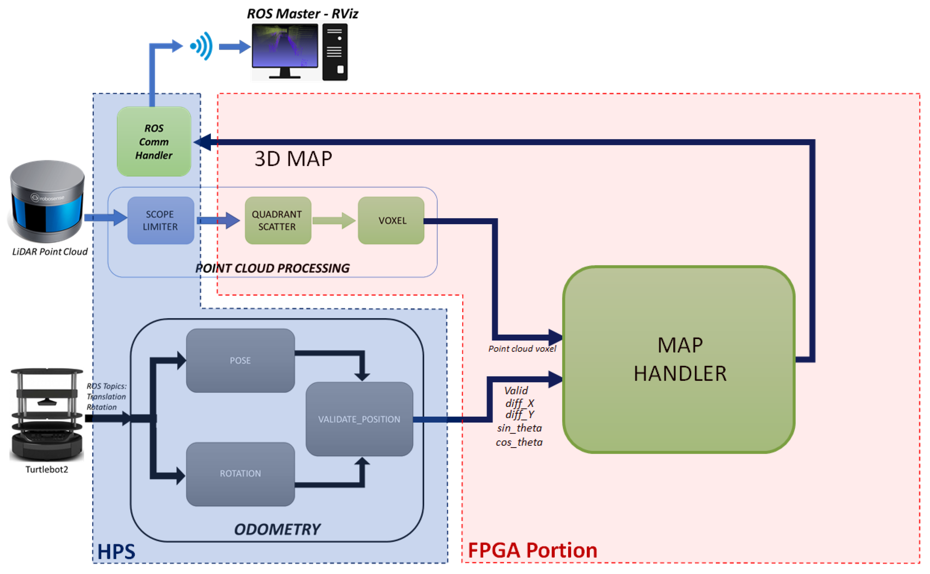
Figure 2 shows the architecture of the eSoC-LAM algorithm, depicting the task distribution between software functions carried out within the HPS and hardware modules off-loaded to the FPGA, resulting from the co-design process. As observed in
Figure 2, eSoC-LAM receives the point cloud data, obtained from the LiDAR RS-16, and the position and rotation angle provided by the Turtlebot2 as input parameters. The system outputs the 3D map of the environment where the robot is located. The 3D map corresponds to an online reconstruction of the environment, which requires an incremental fusion of several overlapping depth maps obtained from the LiDAR, in an unified, continuously updated, 3D representation.
The software implemented in ROS manages the communication with the LiDAR and the robot through ROS
topics, as well as the publication of the 3D map resulting from applying the localization and mapping sequentially. In the
point cloud processing module the point cloud sent by the LiDAR points is restricted in vision range, then grouped and organized using a volumetric approach, in order to reduce the size of the sample to be later integrated into the map [
29,
31]. The voxel filter is responsible for creating a 3D grid, where space is divided into small three-dimensional boxes, which, in turn, group the points obtained by the LiDAR sensor. Those points that fall inside the boxes of the voxel are approximated to the centroid of the box, allowing to reduce the full sample of points to those centroids of the voxels that effectively gather points inside. On the other hand, the
Odometry module uses kinematic equations that describe the motion of a differential mobile robot to obtain the rotation and translation matrix at any given instant. Finally, with the data from the LiDAR sensor grouped and ordered, and the pose information from the odometry model, the
localization and mapping module integrates the voxel points into the current map using a linear transformation. In the following subsections we discuss each of the modules at functional level, and at architectural level for those implemented in hardware.
4.1. Hardware–Software Interface
The DE1-SoC board includes an Intel’s (a.k.a Altera) Cyclone V 5CSEMA5F31C6N, which incorporates an 800 MHz Dual-core ARM Cortex-A9 as hard HPS, and a Cyclone V FPGA running at 50 MHz. Communication between the HPS and the FPGA occurs through bus-based interfaces that allow data to be sent between the two portions of the device. The HPS connects to this bus through a master AXI interface to communicate with the peripherals connected to the processor, including the HPS-to-FPGA bridge. The addressing follows a memory-mapped model, where the hard-core peripherals and the FPGA portion share the memory space that the processor is able to address. The HPS-to-FPGA bridge is a high performance bus with a configurable data width of 32, 64, or 128 bits, that allows the HPS to master transactions to custom hardware slaves deployed in the FPGA fabric. At architectural level, the HPS-to-FPGA bridge can be seen as a shelf of bidirectional registers, that are accessed by both, the HPS and the FPGA.
Operating systems such as Linux, are built under an interrupt-based model where error-prone processes do not possess the ability nor the permissions to interfere with the proper functioning of the processor. The Linux operating system defines two modes to implement protection mechanisms between the processes, known as user mode and kernel mode. User code cannot be executed in kernel mode. When a user process needs to perform an action that is only allowed in kernel mode, such as handling an interrupt or copying data from the registers of a peripheral to the main memory, a system call is made to request that the operating system execute the potentially dangerous operation. This essentially means that the user code cannot access the hardware directly, as there is a great risk that the code will have an error and, in turn, cause the system to crash. The main advantage of the Cyclone V SoC is the ability to make the HPS and FPGA easily communicate with each other. This is simple to achieve in a standard bare-metal application, as there is no protection mechanism in place. However, this is not possible while the HPS is running Linux, as the user code does not have permissions to access the hardware directly. One technique used in embedded Linux environments is to take advantage of the virtual memory system to access any memory-mapped peripherals.
The HPS is able of reading or writing the registers in the HPS-to-FPGA bridge, by referring to each one of the them individually by its correspondent address in the memory space. Linux represents everything as a file, including all the devices connected to the processor. In particular, the file “/dev/mem” represents the contents of the physical memory of the system. To access the textit/dev/mem file, the command “open("/dev/mem", O_RDWR|O_SYNC) in C++ does the trick. Since /dev/mem gives access to the physical memory, the user application must be run under root privileges. Once the file /dev/mem is open, the command mmap() allows to access specific areas of the physical memory, such as the HPS-to-FPGA bridge, which has a fixed address in the HPS memory space. Each individual register in the bridge, can be accessed by a void pointer to the base address of the bridge plus a correspondent offset. A large amount of data are need to be passed from the HPS to the FPGA, i.e., point cloud data from the LiDAR, and back to the HPS, e.g., the generated 3D map. The command memcpy() in C++, is able to copy the values of certain number of bytes from a source location to a memory block pointed to by destination. Even though, memcpy() facilitates passing large batches of data, the copying process still poses as a bottleneck, since copying memory blocks is performed in a sequential fashion.
On the other hand, the FPGA is able to access the individual registers in the HPS-to-FPGA bridge by connecting to the system bus using a wrapper circuit that interfaces the bus protocol into the commands and data structures expected by the hardware. In this case, the hardware in the FPGA is connected to the bus via Avalon slave interface. The compiler incorporates the required AXI-Avalon bridge logic.
4.2. Software Modules—HPS
The entire SoC system was subdivided into the tasks performed by the localization and mapping algorithm, leaving to the HPS only the odometry and robot movement control, the handling of the LiDAR sensor taking advantage of the libraries provided by the manufacturers of both platforms, and the communication with the master ROS running on a desktop computer. All the software was implemented in C++ on ROS Kinetic, which was installed in the HPS under Ubuntu 16.04 as operating system.
4.2.1. Scope Limiter Module
According to the LiDAR’s datasheet [
9], the RS-16 model has a maximum sensing range of 150 m, which is excessive for an indoors application. The
scope limiter module restricts the range of vision of the LiDAR sensor to a few meters around the robot. A sensor with a narrower point of view generates a reduced point cloud, which is desirable since the hardware in the FPGA is able to process a point cloud composed of 16,384 (
) instances due to the limited availability in on-chip memory of the Cyclone V device. It is important to notice, that
scope limiter module can be avoided in the case of using off-chip memory in which case, the hardware would be able to process the 32k+ instances generated by the LiDAR each reading. The use of off-chip memory has been contemplated as a future work.
4.2.2. Odometry Module
The odometry module integrates the ROS libraries in charge of managing sensors and actuators in the robot, encoded in ROS topics. In this case, the pose and orientation data are published by the Turtlebot2 in two different topics. As inputs, the odometry module receives from the robot the translation and orientation information. The odometry module will deliver as outputs, the pose of the robot, the angle and a valid signal that acts as an activation flag to execute localization and mapping.
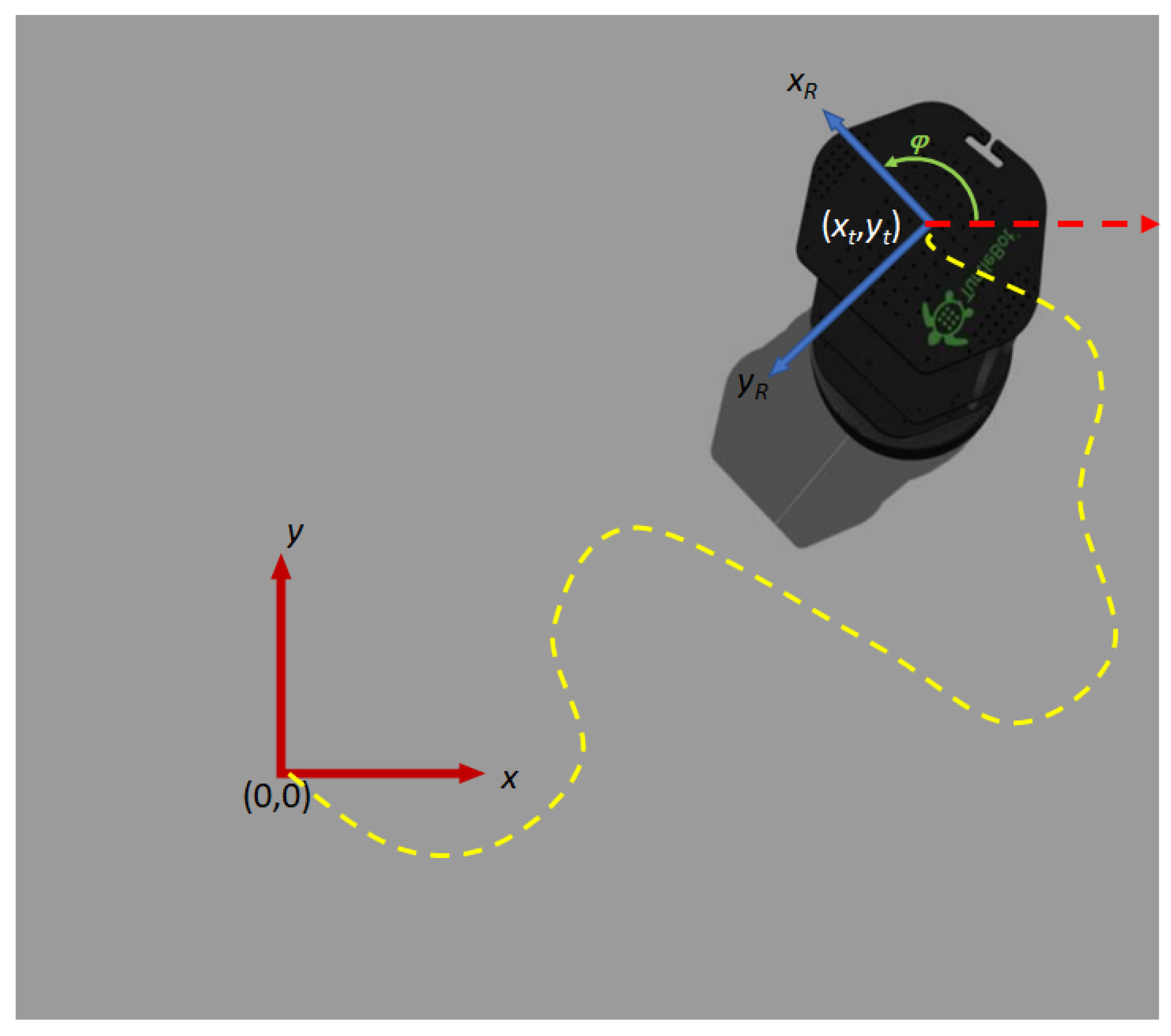
The relative position
, is updated by the
pose module using the ROS topic
/odom, which reads data from the on-board motion sensors and encoders to estimate the change in the robot’s position over time with respect to the position
corresponding to the robot’s position at power-on, as seen in
Figure 3. On the other hand, the orientation corresponds to the rotation of the robot with respect to the
read by the
rotation module from the embarked IMU in the Turtlebot2, using the ROS topic
/mobile_base/sensors/imu_data. The information is processed from a quaternion-based encoding to the the
angle observed in
Figure 3.
Despite the fact that both, the LiDAR and the robot’s sensors can deliver data continuously, the localization and mapping execution is not executed for every incoming reading. On the contrary, the integration of new points to the map is carried out only when the robot moves or rotates a certain threshold value, to maximize the significant amount of new information in each execution of SLAM. Performing localization and mapping too often implies unnecessary use of computational resources, in addition to the possibility that there is no new information to be integrated into the map. The thresholds were determined heuristically, and correspond to a displacement of 0.1 m in either x- and y-axis or a rotation angle .
The Validate_position module is in charge of continuously validating the thresholds and comparing the new position of the robot with the previous poses stored during the construction of the map, to determine if the new point of view has already been visited by the robot and, therefore, the points obtained by LiDAR do not add new information to the map. The block receives as input parameters the current position of the robot and the robot’s orientation angle , to be stored in an array which keeps track of the robot’s poses, using an origin-adjusted coordinate reference system (i.e., position at power-up).
A linear transformation [
32] is used further in the algorithm to update the coordinates of the points in the map to the current point of view. The eSoC-LAM algorithm builds and maintains a map centered on its own inertial coordinate system, and, therefore, the points discovered on the 3D map must be transformed to the current point of view of the robot. The transformation results from the relative position between the last registered pose and the current position (see
Section 4.3.4). However, the positions and angle received from the previous blocks are aligned to the initial frame of reference. In that order of ideas, the module calculates the difference between the current state of the robot-coordinates and angle- and the last position where the localization and mapping was executed. The aforementioned relative movement information is sent to the
Map_handler module in the FPGA represented in the values of the differences
diff_X,
diff_Y and the rotation information encoded in the values
sin_theta and
cos_theta, which in turn allow to calculate the rotation matrix used to transform the coordinates of the current map. In this case, the angle
corresponds to the difference of the absolute reading of the angle
.
4.3. Hardware Modules—FPGA
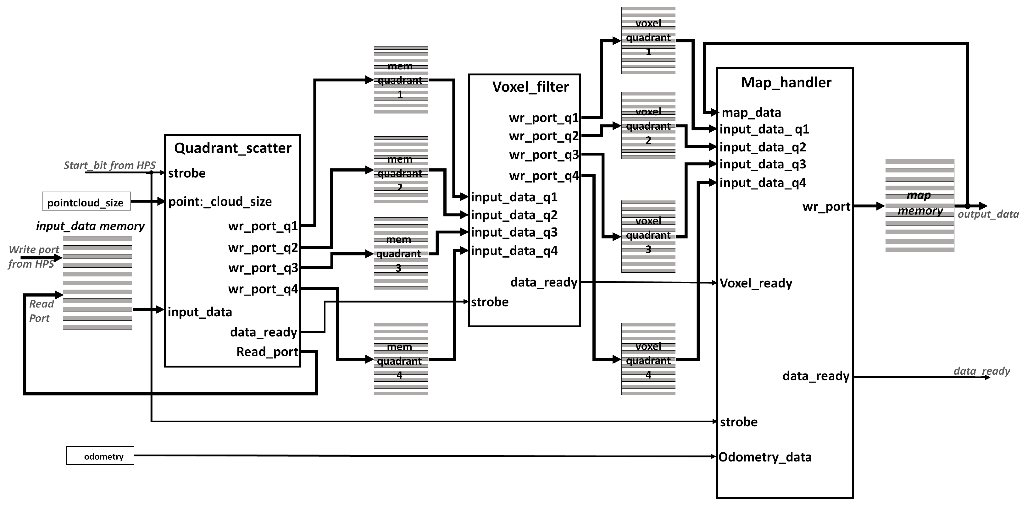
The hardware modules in the eSoC-SLAM algorithm were written in VHLD and deployed in the FPGA portion of the Cyclone V SoC device that is included in the DE1-SOC board. Those blocks depicted in
Figure 2 that were deployed in the FPGA portion of the device are detailed in
Figure 4, which represents the general architecture of the hardware portion. For visualization purposes, some control and status signals have been omitted and the signals that add-up the respective read and write ports for the memories have been grouped together.
As it can be seen in
Figure 4, the point cloud is written directly by the processor in an on-chip memory. The
input_data memory consist in a single-port RAM intellectual property (IP) core with 16,384 (
) words of 96-bits, to store the three coordinates
of each point received in single-precision floating point (FP32) codification. Worth to mention that the data path observed in
Figure 2 propagates and processes
points alongside the hardware stages of the algorithm, therefore, all the storage facilities where single port RAMs configured with the same word size of 96-bits to store the three coordinates in 32-bits and parametrizable capacity. Given the limited on-chip memory available in the FPGA, the number of instances in the point cloud and the maximum number of points that can be stored in the 3D map cannot exceed 16,384 (
). Using an FPGA that includes more logic elements and memory blocks or using external memories, would enable the system to process the entire point cloud which size oscillates around 32k+ points (approximately
). Moreover, the size of the point cloud is also received from the HPS and stored in the register
pointcloud_size.
The first process is carried out by the
Quadrant Scatter module which is in charge of (a) scaling and converting to binary integer each point, (b) separating the point cloud received from the LiDAR into quadrants, and, (c) writing the four memories denoted as
mem_quadrant_i with the points belonging to each quadrant. Next, the
Voxel_filter module applies a voxel-based filter to each of the quadrant point clouds in a parallel fashion, storing the results in the memories noted as
voxel_quadrant_i. Finally, the
Map_handler module uses the odometry information received from the processor to update the 3D map with the new information present in the four
voxel_quadrant_i memories. The map obtained after executing the localization and mapping is stored in the
map_memory module. The 3D map is read by the HPS via the HPS-to-FPGA bridge using the procedure discussed in
Section 4.1, after asserting the
data_ready) signal/register which indicates to the HPS that the processing of a LiDAR reading has finished. The map is then exported to the ROS master located at a remote PC through the HPS, for further analysis and visualization purposes in the RVIZ tool.
4.3.1. Interfaces and General Architecture of Hardware Modules
The implemented system presents a point-to-point interconnection architecture, where successive stages in the algorithm are cascaded using a hand-shake protocol. A consistent interface was selected throughout the design, based on the model presented in [
33], which allows data and events to be communicated between modules. The interface model implements the industrial communications standard called open core protocol [
34] (OCP). The implemented OCP interface is scalable, as it can be integrated into future applications with much larger systems with bus-based or
network-on-chip communications, and result easy to interface with other industrial standards such as AXI, Avalon, among others.
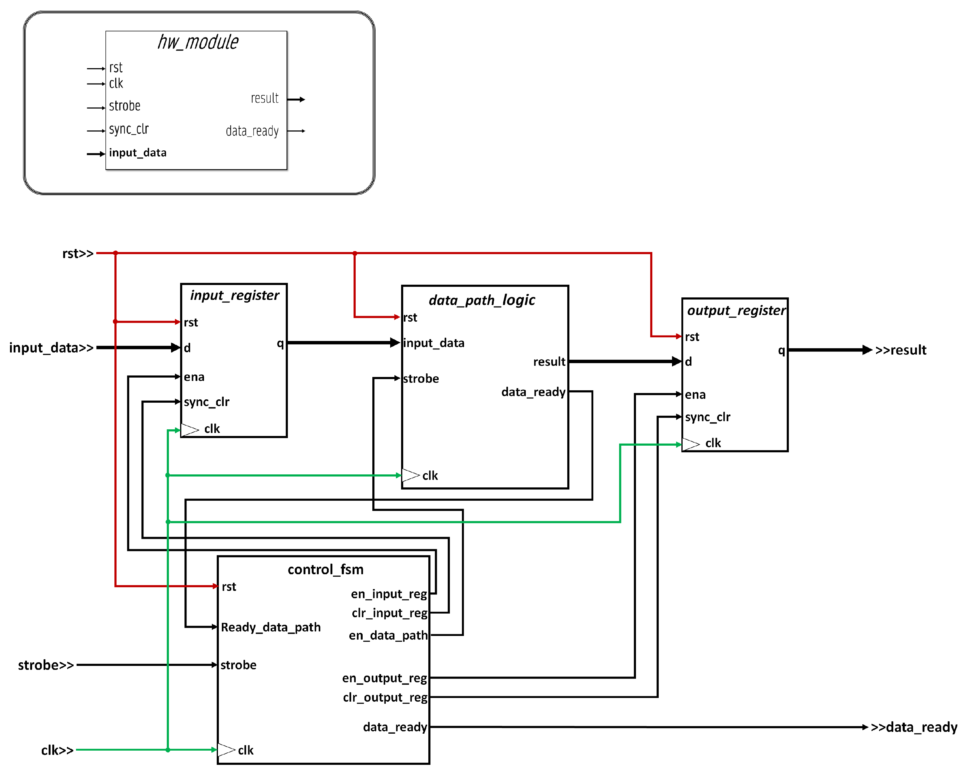
Figure 5 presents the generic interface for all modules implemented in hardware. The interactions between modules are triggered by
events, described as
informative events that involve the passing of raw information, i.e., processed results or information from and to the environment; and
flag events, involving one-bit signals such as flags, control bits, requests, or acknowledge in handshake protocols. The ports used to handle bit events are: (a)
clk—used in digital circuits to synchronize execution; (b)
strobe—is a listening port which is set during a clock cycle to indicate the start of operation; (c)
data_ready—it is a signal that indicates that the operation of a module has finished, its duration is also one clock cycle and (d)
sync_clr—optional synchronous reset signal, that indicates the restart of the module generally to the
idle state in the finite state machines (FSM) that govern the inner operation of the module. On the other hand, the informative events will be given by the data and result ports which will carry output data. These ports will be registered both at the input, being enabled by the
strobe signal, and at the output, whose enable signal is internal.
All modules are designed as a finite state machine with data path (FSMD), where an FSM controls the flow and operation of the data path, as a response to the strobe signal. A strong register balancing was carried out at design stages to achieve higher theoretical operation rate. This implies the design of efficient combinational logic in those data paths that operate in integer arithmetic and strict timed synchronization in those sequential data paths doing floating point processing.
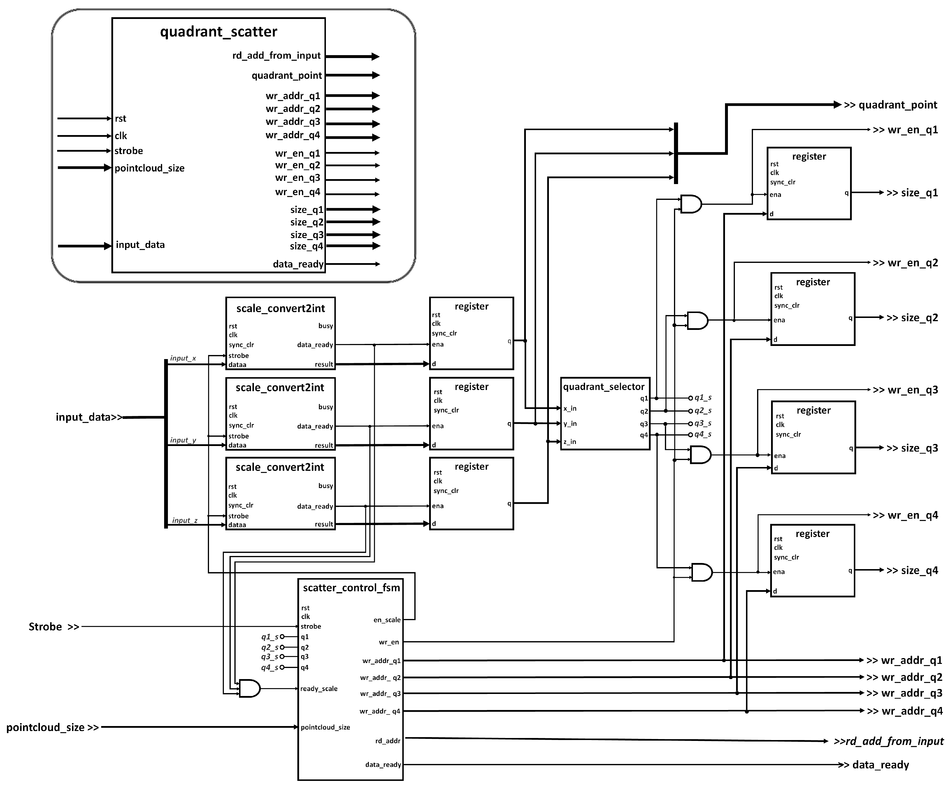
4.3.2. Quadrant Scatter Module
The quadrant scatter module separates the instances of the point cloud by quadrants with the purpose of gaining acceleration by parallelization. Thus, the subsequent voxel filter can run in parallel concurrently for each quadrant. The point cloud is organized by quadrants with respect to the x- and y-axes. The z-axis is not considered as a condition parameter for quadrant grouping, however, within the vision limitation, points in z-axis below −0.38 m are discarded for they belong to the floor.
Figure 6 presents the internal architecture of the
quadrant scatter module. Instances in the point cloud are received from the processor in meters encoded in FP32. An analysis performed at design time stages, identified that the processing related to the quadrant separation and the application of the voxel filter only require simple arithmetic operations (subtraction, absolute value, and comparisons), which implies that it is more beneficial in terms of speed, if such operations were performed in integer arithmetic. Each of the above operations take between 3 and 7 clock cycles for floating point circuits, while the latency of operations in integer arithmetic are bounded by the gate delay of the selected FPGA technology, i.e., between 3 and 6 ns. In addition, resolutions below 1 mm were determined to be not necessary for the designed application. At this stage of the algorithm, the coordinates of the points are scaled by a factor of 1000 so that the point is obtained millimeters, and, finally, a conversion to integer binary encoding is performed.
The
scale_convert2int module in
Figure 6 instantiates IP arithmetic cores for floating point multiplication and floating point to integer conversion, taking 12 clock cycles to operate (6 clock cycles to multiply plus 6 cycles to convert to integer). The
Figure 6 shows three instances of the
scale_convert2int module, which correspond to the respective operations for each of the
x-,
y-, and
z-coordinates, performed in parallel for each new point received.The entire result is subsequently registered when the
data_ready signal of the converters is activated. The points already coded in integer binary, pass through the combinational circuit noted as
quadrant_selector to determine to which quadrant the point belongs, by asserting the corresponding flag signals
,
,
, and
as the case may be. Last, the
scatter_control_fsm module is in charge of controlling the data flow through the different stages and keeping track of the writing pointers for each quadrant.
4.3.3. Voxel Filter Module
Once the different instances of the point cloud have been organized by quadrants, the next step consist in filtering the points using a technique inspired by the
voxel grid method discussed in [
35]. The visible space is divided into small 3D boxes of fixed size, called voxels, which in turn, group the points obtained by the LiDAR sensor that are contained within the volume of the box. Those points that are inside the voxels are approximated to the centroid of the box. The
voxel grid technique is most often used when the poses of the robot are known, a situation that in this application will depend on an optimized odometry model obtained from the Turtlebot2. It is important to define the size of the grid, since it impacts directly in the processing time of the algorithm and memory resource utilization.
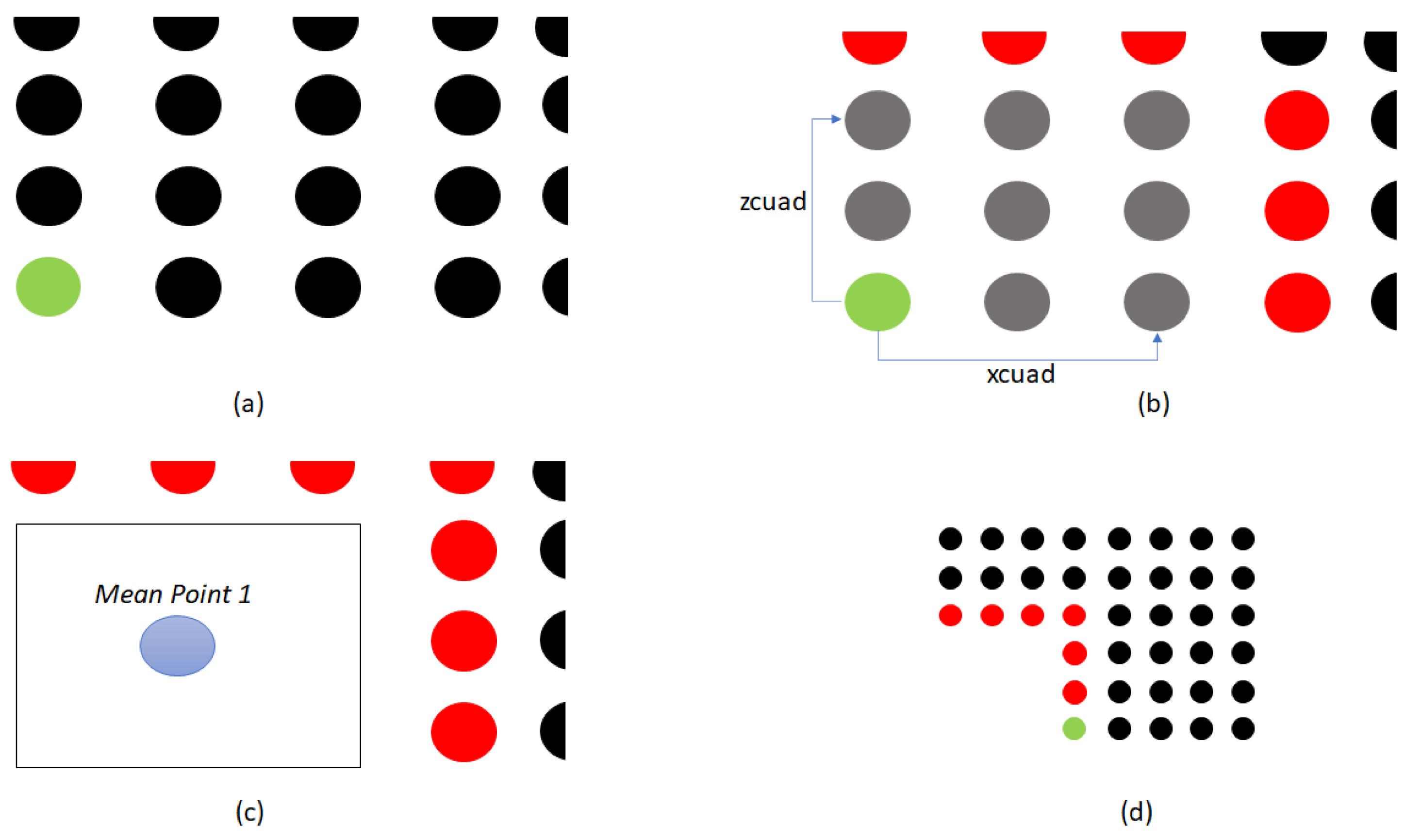
Figure 7 shows an example of the operation of the
voxel filter module presented in two dimensions to facilitate its explanation below.
Figure 7a shows a green instance, called the
anchor point, which corresponds to current point in evaluation. The anchor is taken as the reference point to find and group the neighboring points around it. In
Figure 7, the points are spatially organized, however, it is important to remember that they are stored in a linear array with no particular order. The algorithm compares the distance per
between the
anchor point and all other points in the quadrant memory.
Figure 7b shows the anchor point in relation to the distances
and
, which represents a new voxel cell in the grid. The gray points correspond to the nearest neighbors, whose coordinates are accumulated in each iteration. At the end of comparing the
anchor point with the rest of the points in the cloud, the value of the accumulated sum of the
x,
y, and
z coordinates of all the neighboring points will be stored and, at the end of the iteration, the accumulated value in each coordinate is divided by the total of neighboring points to determine the spatial centroid of the voxel, as observed in
Figure 7c. The points determined as neighbors are included in the cumulative sum by coordinate, while the points that are not considered immediate neighbors (red points in
Figure 7), are taken into account in a new execution of the algorithm. The iterations are repeated, choosing a new
anchor point each time, observed in green in
Figure 7d, until all the points in the quadrant are exhausted. The algorithm returns the centroids of the resulting voxels.
The
voxel filter is executed for each quadrant, by the
voxel quadrant module, which is instantiated four times so that it runs concurrently for each quadrant.
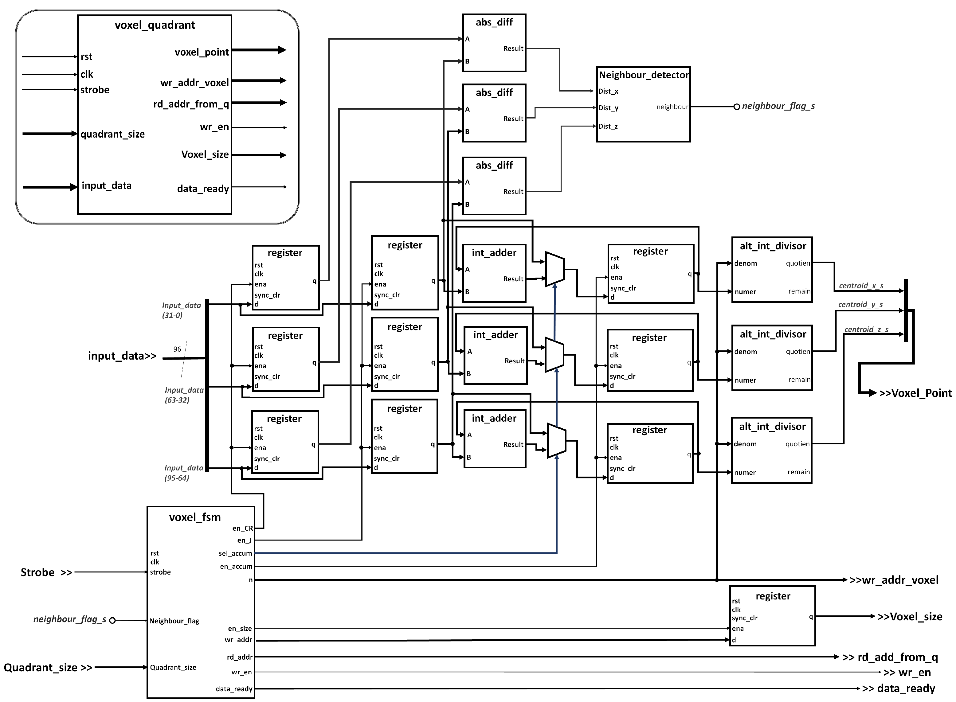
Figure 8 presents the internal architecture of the
voxel quadrant module, in charge of applying the filter over each quadrant memory. The module receives the
strobe bit directly from the signal
data_ready issued by the
quadrant scatter module, indicating that the latter finished the operation and the points are separated by quadrants in the four corresponding memories. The operation performs a convolution of the quadrant on itself, so that each point of the quadrant is compared with all the other points in the same quadrant, to determine which of the points are close, thus can be grouped within a
voxel cell. The neighbouring condition was defined heuristically in 10 cm.
The values of the coordinate of the neighbor points are accumulated and averaged at the end of the iteration to find the centroid of the neighborhood, which correspond to a new voxel. The abs_diff modules are in charge of determining the relative distances on each coordinate between the two points that are being analyzed in any given iteration. In turn, the neigbour_detector module implements combinational logic to determine if two points belong to the same voxel resulting in setting or clearing the neighbor_flag_s flag according to the case. The int_adder adds up the coordinate value with cumulative sum of previous neighbour points. In turn, the alt_int_divisor modules calculate the centroid for each new each new voxel at the last iteration for any given anchor point, by dividing the cumulative sum with the total number of points framed in the current voxel. Last, the Voxel fsm module implements a finite state machine to control the general operation of each of the voxel quadrant sub-systems.
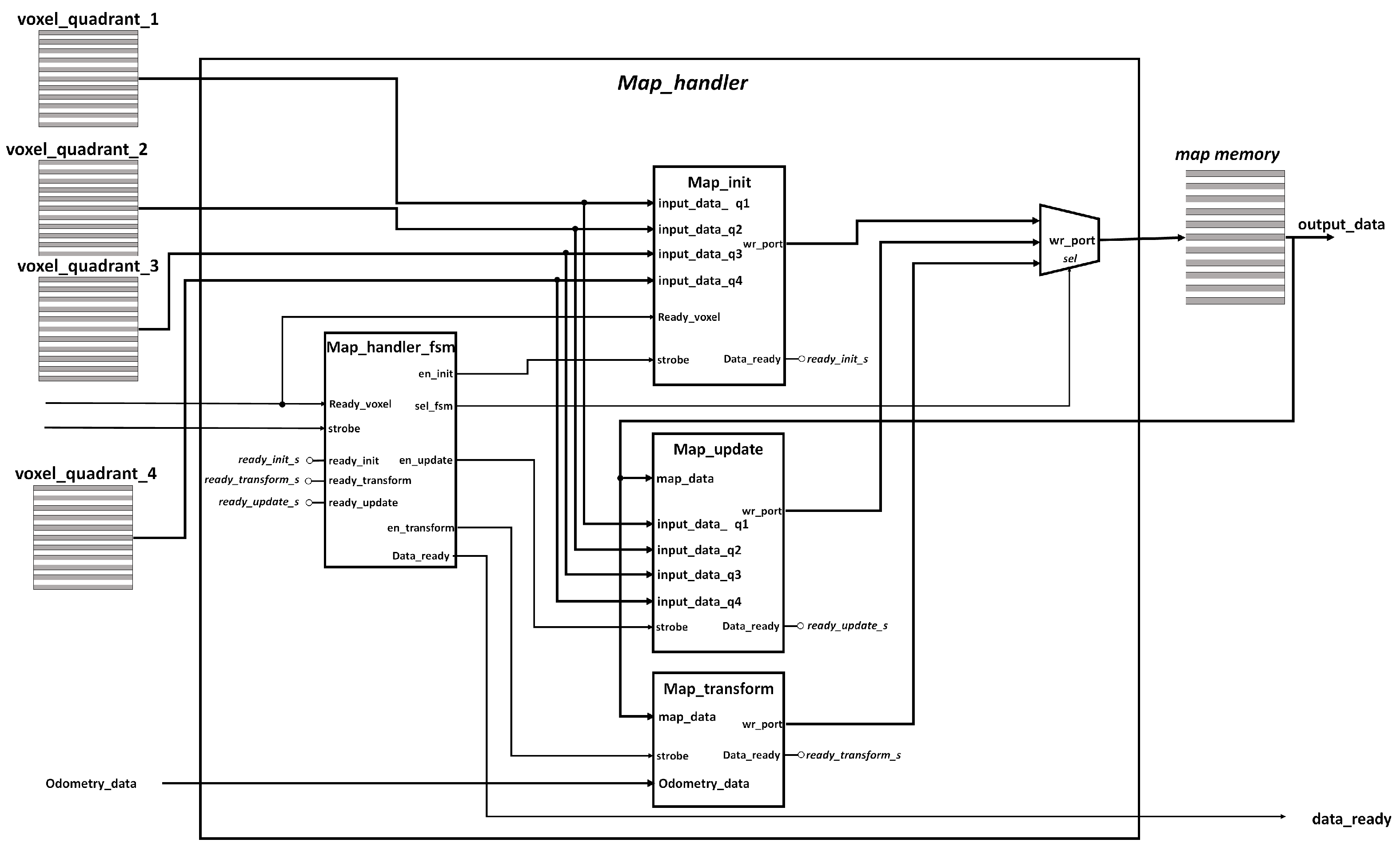
4.3.4. Map Handler Module
The
map handler module is in charge of integrating the new points to the current 3D map, taking into account the new position of the robot. The module receives as inputs: the voxel point cloud coming from the
point cloud processing block, and the position
, the angle
and the activation flag coming from the
odometry block in the HPS. The module outputs the 3D map.
Figure 9 shows the internal architecture the module, which includes four internal sub-modules corresponding to
Map_init:
Map_transform,
Map_update, and
Map_handler_fsm.
Map_init Module
During the first iteration of the eSoC-LAM algorithm the 3D map is empty. The Init_map module allows to initialize the map with the current points of the LiDAR read at the origin of the robot. The Init_map block receives the four voxel point clouds filtered by the point cloud processing block and the size of each one of the point cloudsas input parameters.
Since the previous modules, quadrant scatter and voxel filter, were implemented using integer arithmetic, the representation of the results in the voxel memories is also integer binary encoding, nevertheless, ROS expects the map points in meters in FP32. Therefore, the Map init module reads each point stored in the voxel memories, performs an integer to floating point conversion, followed by a division by the factor of 1000 to obtain meters as a unit. The three coordinates are operated in parallel, and once it has been converted to FP23 and scaled, the point is stored on the map. Similarly to other modules, map init is implemented using a FSM approach to control fetching the points from the voxel memories, the data-flow through the conversion and scaling circuits, and the storing of the new point in the map memory.
Map_transform Module
This block is responsible for carrying out the transformation of coordinates for each point of the map once a new point of view is reached, i.e., the movement threshold is validated by the software running on the HPS. Each point is subjected to a coordinate transformation that responds to the last movement executed by the robot, in order to obtain a map whose origin is the LiDAR’s coordinate frame, describing the world from the robot’s point of view. The Map_transform module operates concurrently with the quadrant scatter and voxel filter modules. Once results are obtained from the voxel filter, the transformed map is ready to be compared with the current points by the Map update module.
Figure 3 shows a rotation of the robot’s
x-axis,
, with respect to the origin’s
x-axis, i.e., the frame of reference. Taking the problem to a
space, it is possible to construct the rotational matrix with respect to the
z-axis for differential mobile robots [
32], which is observed in Equation (
4), where
corresponds to the current orientation of the robot’s with respect to the
z-axis of the global coordinate axis.
The matrix noted as
represents the movement within the global reference frame
in terms of the local reference frame of the robot
, as observed in Equation (
5). For this particular case, the reference coordinate system
determines the coordinates of the world at the immediately previous point of view. On the other hand, the reference frame
corresponds to the current point of view of the robot.
Contrary to Equation (
5), in order to map the environment from the robot’s own inertial coordinate system the eSoC-LAM algorithm must perform the inverse transformation,
. Conveniently,
is an orthogonal matrix (
), which derives Equation (
6), where
corresponds to the coordinates of a current point stored in the map that must be transformed to the robot’s new point of view. Since updating the map occurs if the robot surpasses the movement thresholds, the value of
needs to be adjusted to the difference between the current point in the map and the effective
of movement in
x- and
y-axis and the relative rotation between the two last readings for the angle
. The software running in the HPS sends, the values of the relative movement in each
as parameters to the FPGA, labeled as
diff_X and
diff_Y, and the rotation information in the values
sin_theta and
cos_theta, respectively (see
Figure 2). The underlying hardware that constitutes the
Map_transform module instantiates FP32 IP arithmetic circuits to generate a hardware realization of Equation (
7), along with a FSM to control the fetch of the map points, the coordinate transformation process and storing back the transformed point.
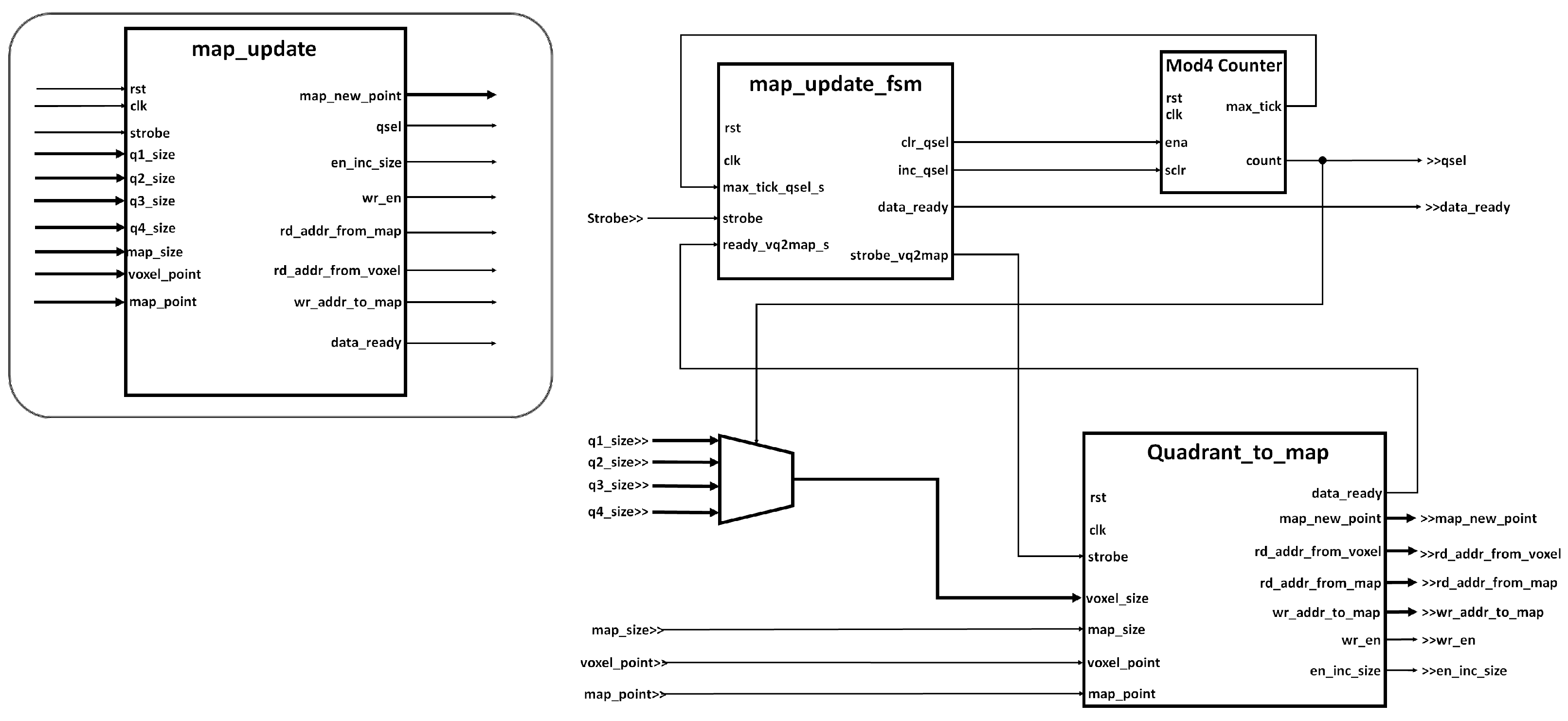
Map_update Module
The purpose of this block is to integrate the new points received from the point cloud processing module into the current map. The Map_Update module compares each point stored in the voxel memories, with all the points currently stored in the map to determine if the new points have been previously marked on the 3D map. To compare the points observed in the current pose of the robot with the points on the map, two options where considered: to calculate the Euclidean distance and to compare each coordinate independently-plus or -minus a tolerance threshold. A simple comparison between coordinates was selected as it implied less processing time. A threshold of ±3.5 cm in each coordinate has been defined to determine if the new point corresponds to the same voxel in the 3D space. If the point is recognized as part of the current voxel, the coordinates of the voxel will be updated with the new point, under the premise that that the robot has a better point of view at its current position. At the end of the iteration, if the new point has not been marked in the map, it will be stored in the last available position in the memory as a new voxel.
The Map_Update block is enabled once both, the transformation of the current map and the execution of the voxel filter are finished. Since the filtered points come in binary integer encoding from the previous modules, the operation of the module initially includes fetching each one of the points from the voxel memories to performing a transformation to FP32 and scaling it to obtain units of meters in each coordinate. Then, the algorithm compares the voxel point with each point stored on the map to determine its neighborhood condition.
The
Map_update module is built using a hierarchical state machine approach, as shown in
Figure 10, where the main FSM,
map_update_fsm, controls which of the voxel memories has to be read. In turn, the
Quadrant_to_map module will be in charge of reading each point in the voxel memory and comparing it with each of the points stored in the current map. An FP32 comparator circuit in is in charge of determining the neighborhood condition for each point, while an internal FSM governs the stages of reading the points from the voxel and map memories, comparison of each point, and storage of the point in the map as the case may be: replacing the values of the most recent point if it is found within the map or adding the new point to the map if it has not been matched after exhausting the current stored points.
5. Results
This section presents the results obtained from deploying the eSoC-LAM algorithm in a Cyclone V SoC platform, implemented and synthesized in VHDL using Quartus Prime 17.1, on a DE1-SoC board. Two experimental approaches where followed to validate the results. A first set of experiments were conducted in simulation using Gazebo, a 3D multi-robot simulator included in ROS, which offers the possibility of simulate robots, objects, sensors, and different environments, both indoors and outdoors [
36]. It should be noted that the simulations carried out seek to reproduce the robot trajectories previously stored in ROS
bags, which allow to store a series of movements in order to guarantee the repeatability of the experiments. It is worthwhile to mention that, although a simulated environment was used in this first sets of experiments, the simulated data were exported and processed by the Hybrid SoC platform, and the generated map was imported back to the host PC. A second set of experiments were conducted using the Turtlebot2 controlled by the DE1-SoC platform, mapping an indoor environment. This analysis focuses on the complete functionality of eSoC-LAM, its capability of generating consistent maps and on the observed acceleration with respect to the software version of the algorithm running in the HPS of the device, and an additional benchmark with the
hdl_graph_slam algorithm running in a high-performance computer that includes an AMD RYZEN 5 3500U@3.2 GHZ processor with 12 GB of RAM.
5.1. Hardware Implementation Results
Table 1 presents the resource utilization of the hardware modules deployed in the FPGA portion (see
Figure 4) after full compilation in Quartus II version
. As observed, the deployment of the architecture in the the Cyclone V SoC device, implied the use of the majority of the FPGA resources, a total of 69% of logical elements were occupied, as well as 80% of the blocks available as on-chip memory. IP memory cores configured as dual port RAM were instantiated to generate the arrays observed in
Figure 4. The memory used to store the point cloud received from the LiDAR via HPS, was set to store 16,384
instances of three FP32 numbers. On the other hand, the
quadrant memories are able to store 2048
integer points, the
voxel memories store 256
, and, finally, the
map memory can hold up to 16,384
map points in FP32 encoding. Although larger memories, specially in the initial point cloud and the map lead to better mapping results, the device does not allow to grow the memories further than the aforementioned sizes without overflow the FPGA capacity. An empirical approach was used in design stages to determine a feasible relation between the sizes of the memories and the mapping capabilities of the algorithm. Finally, the estimated dynamic power consumption of the SoC for this particular implementation is 96.55 mW, while the estimated static power dissipation is 419.72 mW.
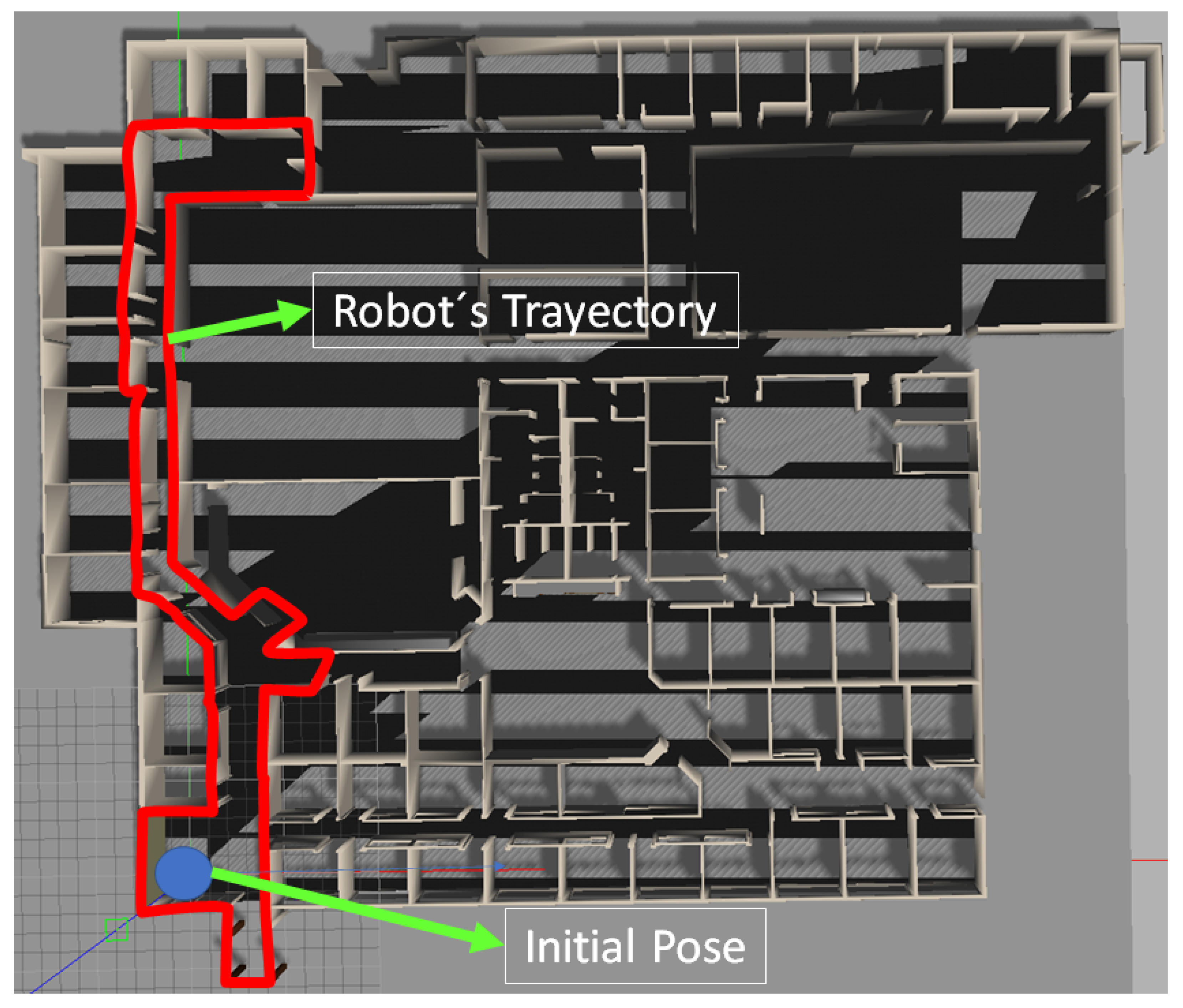
5.2. Mapping Functionality in Simulation
The simulated world used in the experiments comes integrated in the Gazebo platform, and it can be seen in the
Figure 11. The red line shows the path followed by the robot and the blue dot denotes the starting point of the trajectory. The implementation of the localization and mapping algorithm in the FPGA imposed great restrictions in the use of memory, therefore, the instances in the point cloud that must be processed had to be reduced by constraining the LiDAR’s detection range. This also allowed to verify the algorithm’s limitations to generate a consistent map depending on the reduced vision range. Experiments suggested that a detection range under 1.25 m did not generate a usable map.
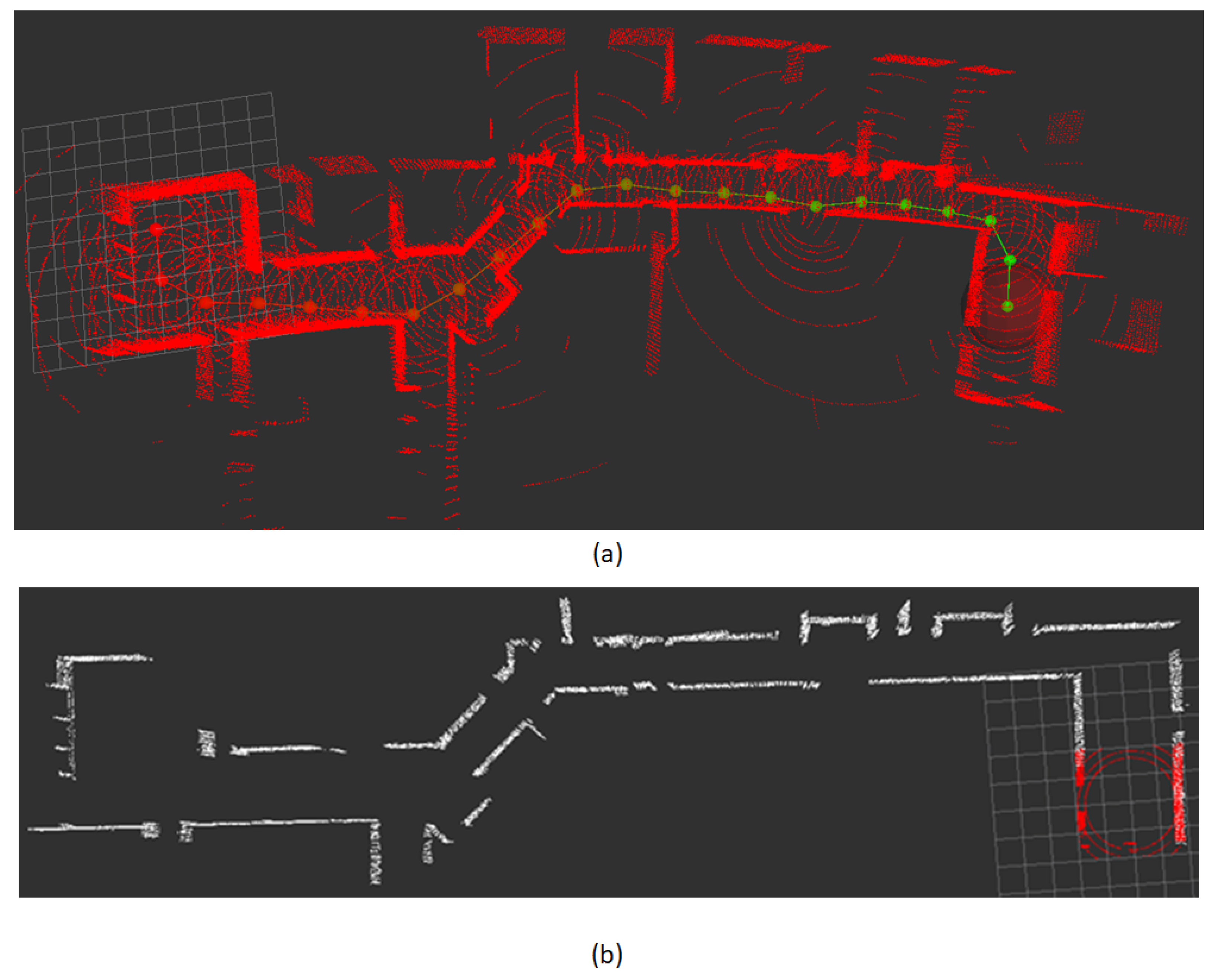
Figure 12a presents the resulting map obtained in simulation by the
hdl_graph_slam when the the robot followed the trajectory observed in
Figure 11.
To verify the eSoC-LAM algorithm, a similar experiment was conducted, were the aforementioned simulated world and trajectory run in Gazebo in a PC, ROS
topics are in charge of sending the sensor information to the DE1-SoC, which, in turn, run eSoC-LAM following the co-design architecture discussed in
Section 4.
Figure 12b presents the resulting map, after the execution of eSoC-LAM, with a restricted field of view of 2 m. The points coloured in red, represent the LiDARS’s limited detection range, generated at the
scope limiter module.
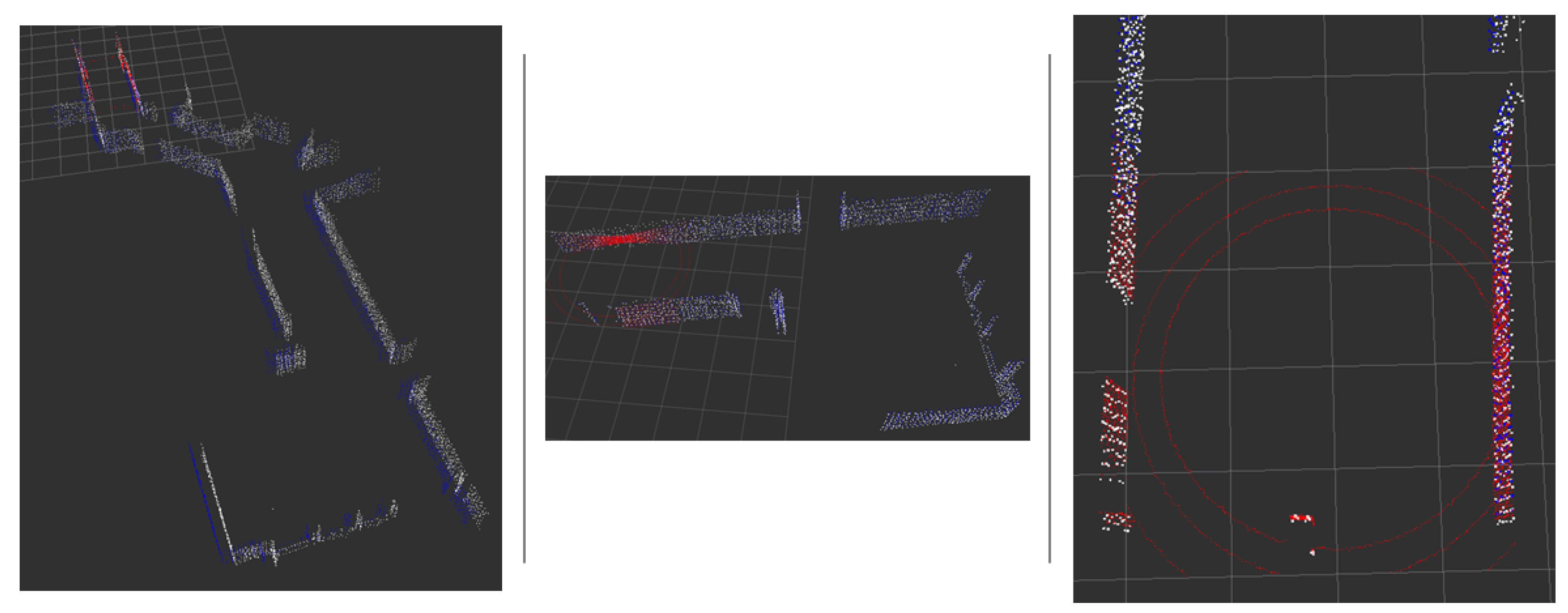
The resulting maps of
hdl_graph_slam and eSoC-LAM are compared in
Figure 13, were the blue points corresponds to the map generated by
hdl_graph_slam and the white points build the map generated by eSoC-LAM. As seen, the general topology of the mapped world is consistent between both versions of the map. The map estimation error was derived from the procedure discussed in [
25], resulting in an error of 3.6%. The map accuracy was determined by comparing the spatial information of the world with the generated 3D map. It is worthwhile to mention that, in the simulation neither the robot’s odometry nor the LiDAR present uncertainty or noise.
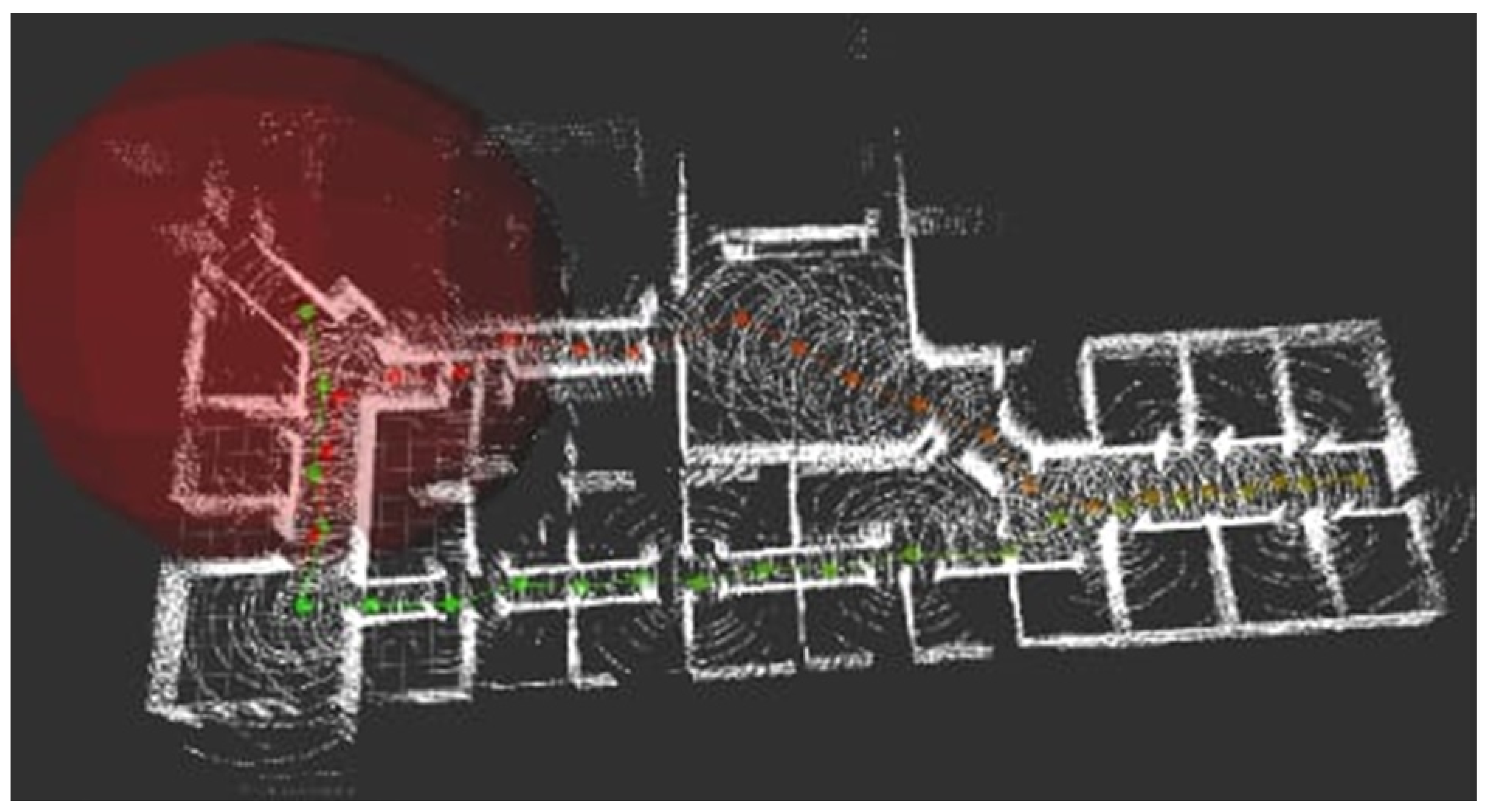
5.3. Mapping Functionality in Indoors Operation
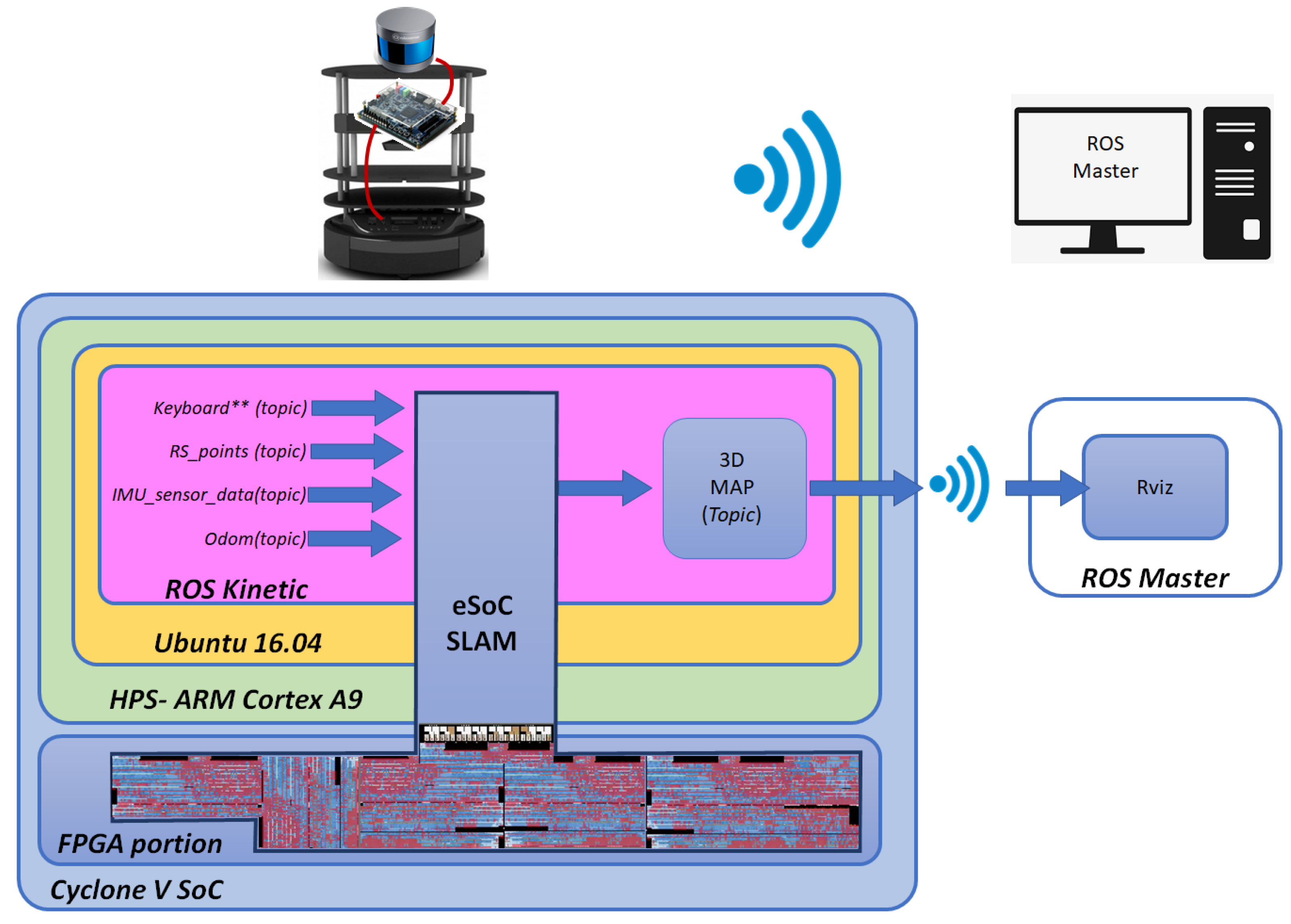
The final set of experiments consisted on running eSoC-LAM in the DE1-SoC as shown in
Figure 14. Data are obtained directly from the LiDAR connected to the De1-SoC, as well as from the Robot’s odometry and IMU, using the correspondent ROS topics. The
keyboard topic is used for remote operation of the robot from the PC running ROS Master. At the same time, a new ROS topic called
3D map is created to publish the generated map. The ROS master is in charge of reading the published map to be displayed in RVIZ and to store it for further analysis. The robot was operated in an apartment as an indoors case study, and the procedure can be observed at the following link:
https://.be/vBJ8NSNYme4 (accessed on 24 May 2021), as described in the
Supplementary Materials in
Section 6.
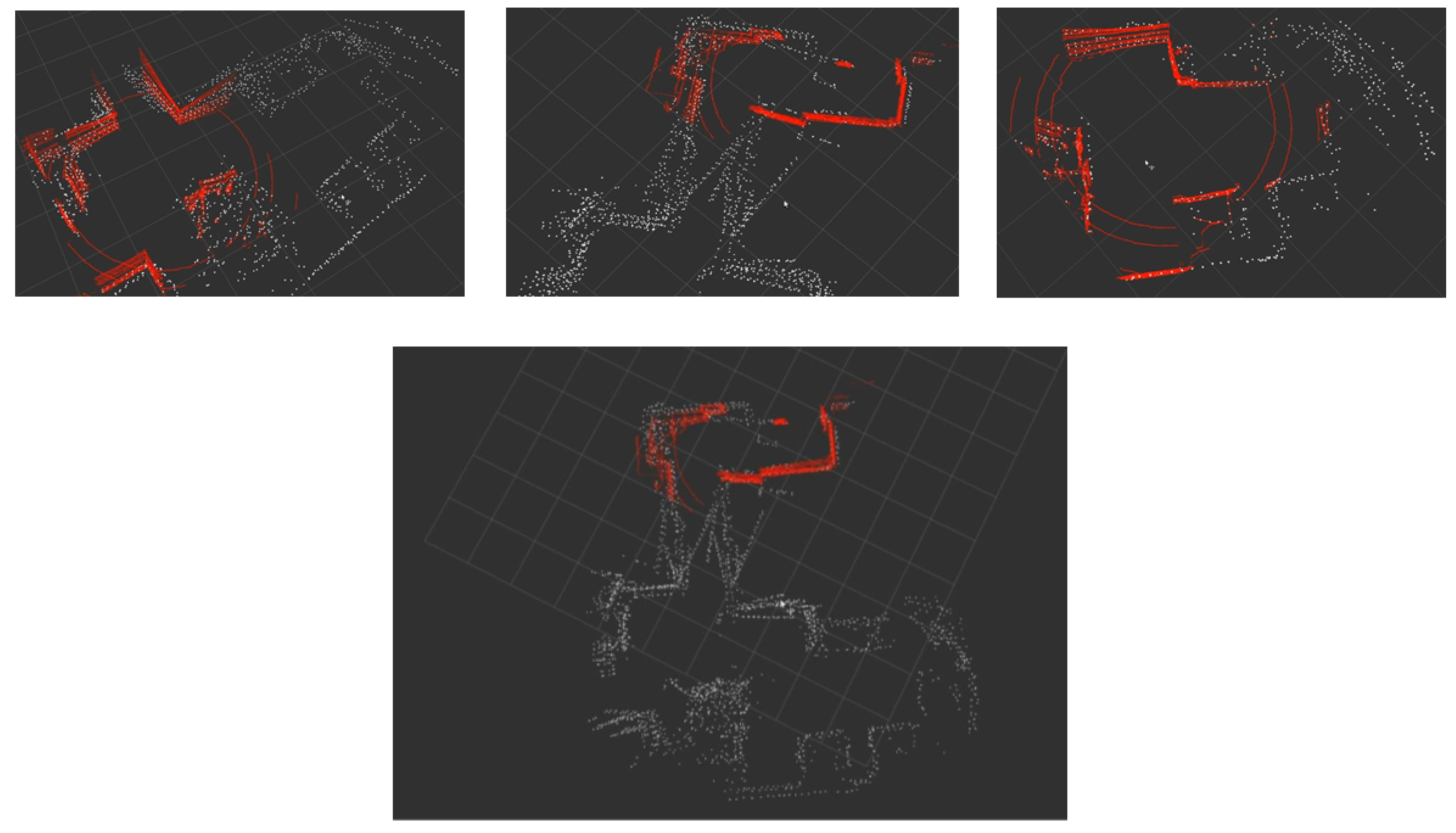
Figure 15 presents the incremental construction of the map as the robot navigates through the environment. The red points correspond to the limited range of vision generated by the
scope limiter module. The bottom image in
Figure 15 depicts the full map generated by the eSoC-LAM algorithm in a hybrid architecture. The map presents high sensitivity to the rotations of the robot, which in turn limited the speed at which the turns were executed.
5.4. Timing Aspects
The latency of the system was determined from the moment that a new LiDAR reading is received until the FPGA sets the data_ready bit. Thus, the measured latency would not only contemplates the time used by the hardware modules, but also takes into account the timing imposed by the software routines and the time used in passing the point cloud from the HPS to the FPGA.
The eSoC-SLAM algorithm presents variable latency depending on certain operation conditions. The first iteration of the algorithm occurs faster than subsequent executions since the map is empty and no comparison procedures need to be executed. The first execution of eSoC-SLAM took an average time of 10 ms. A different circumstance occurs hen the robot executes a turn without displacement, which only implicates the coordinate transformation of the map to the robot’s current point of view. A pure turn took between 2 and 7 ms, which depends on the size of the current map. The final scenario corresponds to the integration of new readings to the current map, which also depends on the current size of the map. For this last case, a variation between 10 and 100 ms was measured, with an average latency of 31 ms, which implies near 32 fps. Currently, the robot is limited to a maximum speed of 2 m/s, which implies a new reading from the sensor every 50 ms as the movement threshold was set to 10 cm, which gives almost 20 ns of slack before a new reading arrives. Remember, that the FPGA is running at 50 MHz, nevertheless, the operation frequency can be further increased to achieve even faster results. The compilation report in Quartus Prime states a theoretical maximum operating frequency for the hardware modules of 717 MHz, which was achieved thanks to a exhaustive register balancing during hardware design.
Finally,
Table 2 presents the acceleration results obtained by the eSoC-LAM algorithm. A full software version of eSoC-SLAM was constructed at design stages in order to verify the mapping functionality of the algorithm. The software version of the algorithm was deployed in both, the HPS present in the Cyclone V device (800 MHz ARM Cortex A9, Ubuntu 16.04) and in a high performance PC with an AMD RYZEN 5 3500U @ 3.2 GHZ processor. The hybrid SoC architecture achieved a speed-up of 6.5× in comparison to the software version running on the HPS. Even though, running a full software version of eSoC-SLAM in the HPS takes most of the resources of the system, the ARM can achieve almost 5 fps, which corresponds to an average processing time of 203 ms per sensor reading, in comparison to an average of 31 ms for the hybrid architecture, while at the same time, the HPS is incapable of executing
hdl_graph_slam. The hybrid SoC architecture resulted even faster by a factor of 2.4× compared to the execution time of eSoC-SLAM in the high-end PC. On the other hand, compared to the execution of
hdl_graph_slam in the PC, the hybrid SoC implementation presented an average speed-up of 113.6×.
This successful implementation of a mapping algorithm in a hybrid SoC architecture demonstrates the feasibility of implementing complex algorithms present in robotics, which nowadays are constrained to be deployed in high performance PC platforms, achieving not only considerable acceleration, but also, a reduction in the size of the hardware that controls a robot.
6. Discussion
The design of a localization and mapping algorithm is described in this document, aimed to deployment on embedded computing platforms and hybrid SoC platforms. The designed architecture and co-design results, developed in the present investigation was comprehensively described and validated by comparing the resulting mapping capabilities with the ROS library, hdl_graph_slam. Consistent results in mapping the environment and location of the robot were obtained, compared with the Graph SLAM algorithm included in ROS’s own libraries, obtaining a mapping error of error of 3.6% in a simulated environment.
Contrary to approximations reported in the literature, the result of the present investigation managed to implement a complete back-end of the online SLAM algorithm in reconfigurable hardware, leaving to the processor only tasks related with the movement of the robot, and the readings of the robot’s sensors and the LiDAR. In addition to the mapping capabilities, the hybrid SoC architecture achieved reached an average speed-up of 2× in comparison to a software version running in an AMD RYZEN 5 3500U @ 3.2 GHZ processor with 12 GB of RAM, and an acceleration of 6.5× in comparison to a software version running on the ARM-Cortex A9 present in the Cyclone V device. Compared to the execution of hdl_graph_slam, the Hybrid SoC implementation presented an average speed-up of 113.6×.
Although the results of this research are promising, it is possible to continue the development of applications in robotics using SoC platforms. The SLAM model can be extended to use depth information [
37], loop-closure [
38] procedures, and a visual odometry, in order avoid depending on robust odometry models and costly optimizations and only focus on high-performance sensors. This can additionally lead SLAM to aerial robots, where the kinematics substantially change when new movements coming into play.
Additionally, the FPGA included in the Cyclone V SoC device has limited memory resources. For the present investigation, most of the on-chip memory resources of the FPGA were used, which limited both the size of the point cloud received from LiDAR and the maximum size of the map that the algorithm can generate at a time. A complete implementation must include the SDRAM memories present in the DE1-SoC board that would allow a practically unlimited resource use (64 MB+) for this application. Further optimizations in the hardware design are contemplated as future work to extend the system storage capabilities and enhance latency.
Finally, it is important to consider artificial intelligence as a tool that can bring SLAM applications to small platforms. The application of AI in robotics issues can be widely observed in the literature, however, mapping and localization approaches are still in the early stages of research.


 ,
, 


