Abstract
This paper presents a compact and simple reconfigurable antenna with wide-band, dual-band, and single-band operating modes. Initially, a co-planar waveguide-fed triangular monopole antenna is obtained with a wide operational frequency band ranging from 4.0 GHz to 7.8 GHz. Then, two additional stubs are connected to the triangular monopole through two p-i-n diodes. By electrically switching these p-i-n diodes ON and OFF, different operating frequency bands can be attained. When turning ON only one diode, the antenna offers dual-band operations of 3.3–4.2 GHz and 5.8–7.2 GHz. Meanwhile, the antenna with single-band operation from 3.3 GHz to 4.2 GHz can be realized when both of the p-i-n diodes are switched to ON states. The proposed compact size antenna with dimensions of 0.27λ0 × 0.16λ0 × 0.017λ0 at the lower operating frequency (3.3 GHz) can be used for several wireless applications such as worldwide interoperability for microwave access (WiMAX), wireless access in the vehicular environment (WAVE), and wireless local area network (WLAN). A comparative analysis with state-of-the-art works exhibits that the presented design possesses advantages of compact size and multiple operating modes.
1. Introduction
Nowadays, the wireless technologies, such as WLAN, WiMAX, fifth-generation (5G) systems, etc., have been widely used, and they are usually integrated into a single electronic device. It raises a requirement of a single antenna capable of working at various frequency bands. This type of antenna is of great significance for the modern wireless communication systems.
To fulfill this requirement, the most common method is to design an antenna with ultra-wideband (UWB) operation. Many literary works reported UWB antennas [1,2,3]. Alternatively, multi-band antennas have also been demonstrated as another effective solution [4,5,6]. However, the wide-band or multi-band antennas are featured by a critical drawback of their fixed operating frequency band. In other words, the resonant frequency of the antenna cannot be altered as per the user requirement. This lack of flexibility leads to co-channel interference and more power consumption. On the other hand, few UWB antennas having notch reconfigurability were also reported in the literature. Still, the usage of larger antenna size along with complex structures arises a lot of complexity and, thus, limits them for compact size and mass production [7,8].
Due to the discrepancies mentioned above, demand for the multi-mode reconfigurable antennas used in various wireless services has increased over the years [9]. Reconfigurability is the ability to adjust the antenna’s characteristics such as resonant frequency, polarization, or radiation pattern [10,11]. Instead of using multiple antennas operating at various frequencies, it is desirable to use a frequency reconfigurable antenna that improves performance and reduced footprint and cost. A frequency reconfigurable antenna is able to switch the operating frequency to the desired range. Most of the reported frequency reconfigurable antennas concentrate on changing the operation from a single-band to another shifted single-band [12,13,14,15] or from a multi-band to a single-band [16,17]. Several works have focused on changing operating band from wide-band to single-band [18,19,20,21] or multi-band [22]. As per the author’s best knowledge, there is only one reconfigurable design proposed in [23], which can offer wide-band, multi-band, and single-band operation characteristics.
In summary, the antennas in [12,13,14,15,16,17] have narrow operating bandwidth (BW) and are only suitable for narrow-band applications. Meanwhile, although the wide-band operation can be achieved in [18,19,20,21,22], they are only able to produce either single-band [18,19,20] or multi-band [22] modes. Additionally, the magneto-electric dipole [18] and Vivaldi structures [21,23] have a large overall size and unidirectional beams. These characteristics are not suitable for portable devices, where compact size and bi-directional radiation patterns are more preferred. Beside these, literature work also reports some artificial intelligence driven optimization techniques [24,25,26]. However, these techniques require some extra skill sets to utilize them to design antenna, which may result in a lot of complexities with respect to an antenna designer.
This paper focuses on designing multiple operating modes antenna with compact size and bi-directional beam characteristics. The antenna consists of a co-planar waveguide fed triangular monopole antenna and two additional stubs, which are connected to the patch through p-i-n diodes. The single-band, dual-band, and wide-band operations can be conveniently accomplished by switching ON/OFF these p-i-n diodes. The measured data indicates that the presented antenna demonstrates good characteristics for wide-band (4.0–7.8 GHz), dual-band (3.3–4.2 GHz and 5.8–7.2 GHz), and single-band (3.3–4.2 GHz).
2. Antenna Geometry
The schematic of the proposed frequency reconfigurable antenna is illustrated in Figure 1. The antenna consists of a triangular monopole and two stubs. The two p-i-n diodes are inserted in between the patch and the stubs. The proposed configuration uses p-i-n diode of type HPND-4005 [27]. The antenna is designed on 1.6 mm thick FR4 substrate having a dielectric constant, εr = 4.4 and loss tangent of tan δ = 0.025. The antenna is simulated and characterized using the finite element based electromagnetic solver, High-Frequency Structure Simulator (HFSS). To mitigate the effects of the connector while measuring, the antenna is excited using the model of commercially available SMA connector.
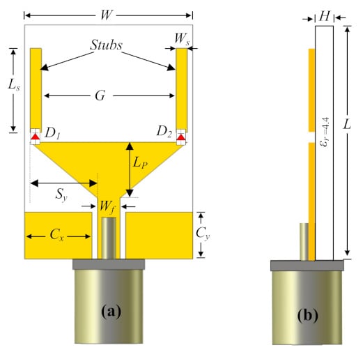
Figure 1.
Design layout of the proposed antenna: (a) Front and (b) side view.
3. Antenna Operation and Characteristics
Initially, the rectangular quarter wave monopole antenna using Co-Palanar Waveguide (CPW) feeding scheme was designed to operate at fr = 5.2 GHz and its length can be defined using following equations:
where c is the speed of light, εeff is the effective dielectric constant, εr and H represents dielectric constant and thickness of the substrate, whereas W is the width of the monopole. In the next step, the rectangular patch is optimized to obtain triangular monopole antenna by truncating the lower corners. Moreover, two rectangular stubs are incorporated to extend the length of the monopole. The length of the stub (Ls) is chosen so that the overall length of the monopole Lp + Ls is almost quarter wavelength of the resonant frequency. In the presented case, the desired resonant frequency at the lower frequency range is 3.5 GHz. The optimized antenna exhibits best performance for all operating modes and the final optimized antenna’s dimensions are: L = 25, W = 15, H = 1.6, Cx = 6, Cy = 5, Ws = 1, Ls = 8, Sy = 6, G = 12, Wf = 2, Lp = 8.5 (unit: mm). The reconfigurability of the proposed antenna can be attained by electrically controlling the ON and OFF states of the p-i-n diodes. The different operating modes are as follows:
- (a) Wide-band operating mode
When two p-i-n diodes are switched to OFF state, only the triangular monopole is excited and this antenna can provide a wide impedance BW from 4 GHz to 7.8 GHz, equivalent to 64.4%. The triangular monopole is modified from the rectangular monopole antenna by truncating lower corners. By tuning the truncated corner, the wide-band operation can be attained. This can be demonstrated by observing Figure 2b, which shows the simulated reflection coefficients for multiple values of Sy.
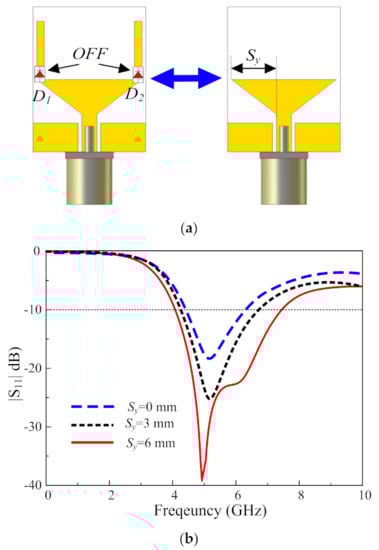
Figure 2.
(a) Equivalent geometry and (b) simulated |S11| for different values of Sy in the wide-band operating modes (both p-i-n diodes are OFF).
- (b) Dual-band operating mode
Dual band operation can be attained by turning the one of the two diodes ON, as shown in Figure 3a. Subsequently, the length of the resonating structure increases and due to this antenna resonates in the lower frequency band as well. An insignificant degradation in antenna performance is observed at the higher frequency (6.2 GHz), as S-parameter curve shifts slightly upward. However, antenna is still resonating for this band. The two operating bands achieved ranges from 3.2 to 4 GHz and 5.5 to 7.5 GHz, as illustrated in Figure 3b.
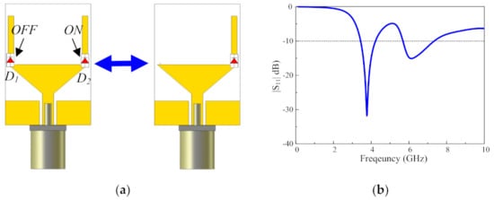
Figure 3.
(a) Equivalent geometry and (b) simulated |S11| of the proposed antenna working in dual-band operating mode (D1 is OFF and D2 is ON).
- (c) Single-band operating mode
When both p-i-n diodes are switched to ON state, as shown in Figure 4a, both of the stubs are excited, and a single-band at 3.5 GHz is obtained, as depicted in Figure 4b. However, this will significantly affect the antenna performance at the higher frequency (6.2 GHz), and the operating band at this frequency degrades and shifts above −10 dB.
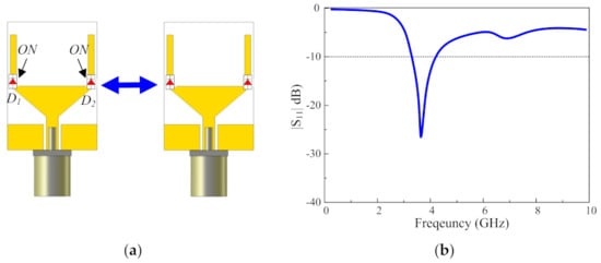
Figure 4.
(a) Equivalent geometry and (b) simulated |S11| of the proposed antenna working in the single-band operating mode (both p-i-n diodes are ON).
- (d) Surface current distribution
In order to further investigate the radiation mechanism of the proposed antenna, surface current distribution at the selected frequency of 3.5 GHz is discussed in this section. It can be observed from Figure 5a that the current is mainly concentrated around the bottom of the monopole antenna, thus, no resonance was possible. Besides, the very limited current flowing around stubs also shows that stubs have no contribution to the wide-band response of the antenna.
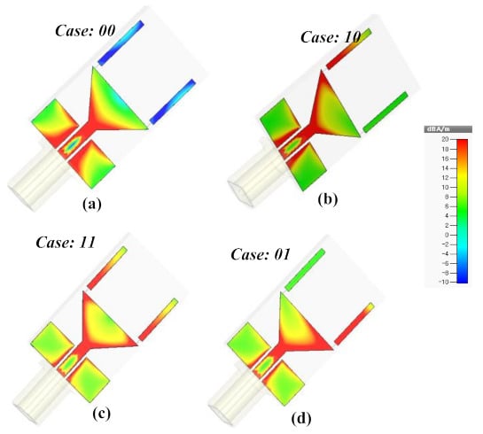
Figure 5.
The surface current density at 3.5 GHz for different switching cases of the proposed antenna. (a) Case-00; (b) Case-10; (c) Case-11; (d) Case-01.
On the other hand, for Case-01 or Case-10, only a single rectangular stub is excited due to switching of either diode. This stub redistributes the current flowing on the surface of the patch, resulting in a dual-band operation. In this case, when the single stub is connected to the patch, the current partially flows to the stub, as depicted in Figure 5b,c, which causes the resonance at the lower band.
In the last case-11, when both the stubs are connected to the patch, since both diodes are in On-state, as shown in Figure 5d, the current continues flowing to these stubs, thus, increasing the effective length of the resonating structure. Consequently, a resonating band is obtained at the lower frequency.
4. Experimental Results and Discussion
To endorse the performance of the proposed antenna, various parameters such as S-parameters and far-field characteristics are measured and compared with the simulated results. For measurement purposes, the antenna is fabricated using standard Photolithography technique along with the switching circuit on a separate board. Figure 6 illustrates the prototype of the proposed antenna. The succeeding sections provide the comparative analysis of simulated and measured results.
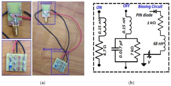
Figure 6.
(a) Fabricated antenna with biasing circuit and (b) equivalent circuit model for the PIN diode (ON and OFF state) and biasing circuit.
- (a) S-Parameters
Figure 7 illustrates the simulated and measured S-parameter results for different operating modes. The measured results in Figure 7a demonstrates that for the wide-band operating mode, the proposed antenna resonates for the 4.0–7.7 GHz frequency band. Whereas, for the dual-band operating mode, the two bands for antenna radiates are 3.3–4.2 GHz and 5.8–7.5 GHz, as shown in Figure 7b. Similarly, the measured single-mode operating frequency band is 3.5–4.2 GHz, as illustrated in Figure 7c. It can be seen that measured and simulated results are in good agreement. However, the insignificant differences are due to fabrication errors and imperfection in the measurement setup.
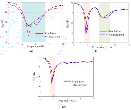
Figure 7.
The simulated and measured |S11| for different operating modes (a) wide-band, (b) dual-band, and (c) single-band.
- (b) Far-Field Results
The far-field characteristics of the proposed antenna are measured at different orientations by rotating the antenna under test. Radiation plots at different frequencies and operating modes in the E and H-plane for the proposed antenna are depicted in Figure 8. The antenna shows nearly identical radiation patterns at all resonating frequencies with an omnidirectional radiation pattern at 3.6 GHz, 4.6 GHz, and 6.6 GHz in H-Plane (φ = 90°), however in E-Plane (φ = 0°), the antenna exhibits a bidirectional radiation pattern at all investigated frequencies.
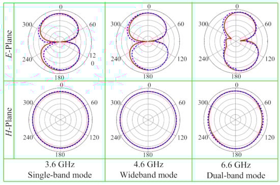
Figure 8.
Measured and simulated radiation plots of the proposed antenna at various frequencies.
The gain and radiation efficiency of the proposed antenna at different modes of operation are shown in Figure 9 and Figure 10, respectively. The measured peak gain of 4.1 dBi is attained for both wide-band and dual-band modes, whereas for a single-band operating mode peak gain of 3.4 dBi is obtained.
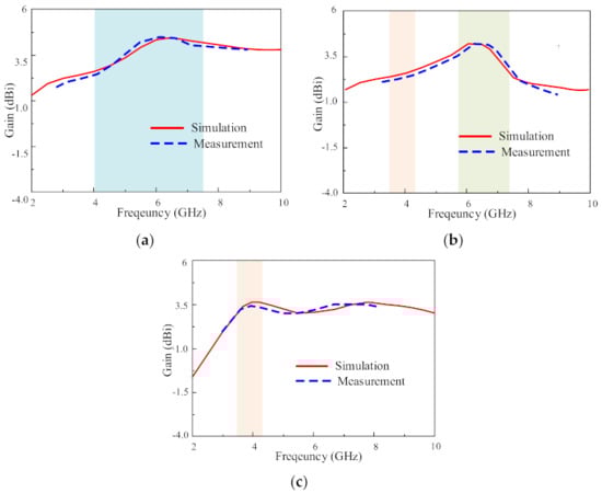
Figure 9.
Gain of the proposed antenna for different operating modes: (a) wide-band, (b) dual-band, and (c) single-band.
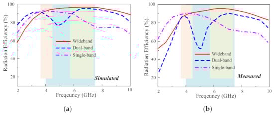
Figure 10.
The (a) simulated and (b) measured radiation efficiency of the proposed antenna for different operating modes.
Moreover, the maximum radiation efficiency of 92%, 89%, and 90% is obtained for wide-band, dual-band, and single-band operating modes, respectively. It is clearly exhibited from these results in Figure 8, Figure 9 and Figure 10 that simulated and measured results are coherent. However, minor inconsistencies may be due to fabrication errors and losses across connectors.
Finally, the performance comparison between the proposed design and other related works are depicted in Table 1. It is noted that since this paper focuses on the antenna with the bi-directional radiation beam, only reconfigurable antennas with this feature are considered. It can be seen that the antenna is of compact size with a greater number of operating modes (single band, multi-band, and wide-band) with just two p-i-n diodes by adjusting the bias states of two p-i-n diodes without any modifications to the radiating element. The proposed antenna is a potential candidate for cognitive radio and multi-mode communication systems.

Table 1.
Comparison with the state-of-the-art antennas. (λ0 is the wavelength at the lowest operating frequency.)
5. Conclusions
In this article, a compact reconfigurable monopole antenna with wide-band, dual-band, and single-band operations for various wireless applications is presented. The proposed antenna can operate in wide-band (4–7.8 GHz), dual-band (3.3–4.2 GHz, and 5.8–7.2 GHz), and single-band (3.3–4.2 GHz) modes by adjusting the switching state of the only two p-i-n diodes without any modifications in the radiator. Consequently, the proposed antenna can cover the various multi-mode communication systems based on system demands, such as WiMAX, WLAN, WAVE, and 5G. Owing to its easy design, compact size (0.27λ0 × 0.16λ0 × 0.016λ0 at 3.3 GHz), and good radiation characteristics for various operating bands, the proposed antenna can potentially be used in multi-mode communication systems.
Author Contributions
Conceptualization, W.A.A., N.H. and M.A.; data curation, formal analysis, W.A.A., S.I.N. and N.H.; funding acquisition, M.A. and E.L.; investigation, S.I.N., M.A. and N.H.; methodology, W.A.A. and N.H.; project administration, M.A. and E.L.; resources, M.A., N.H., A.I. and H.H.T.; validation, W.A.A., N.H. and M.A.; visualization, writing—original draft, W.A.A., N.H. and S.I.N.; writing—review and editing, S.I.N., W.A.E.A., N.H., A.I., H.H.T. and M.A. All authors have read and agreed to the published version of the manuscript.
Funding
This research received no external funding.
Data Availability Statement
All data have been included within the manuscript.
Acknowledgments
This work is partially supported by Antenna and Wireless Propagation Group (AWPG); https://sites.google.com/view/awpgrp.
Conflicts of Interest
The authors declare no conflict of interest.
References
- Yan, S.; Soh, P.J.; Vandenbosch, G.A. Wearable ultrawideband technology—A review of ultrawideband antennas, propagation channels, and applications in wireless body area networks. IEEE Access 2018, 6, 42177–42185. [Google Scholar] [CrossRef]
- Mahmud, M.; Islam, M.T.; Misran, N.; Almutairi, A.F.; Cho, M. Ultra-wideband (UWB) antenna sensor based microwave breast imaging: A review. Sensors 2018, 18, 2951. [Google Scholar] [CrossRef] [PubMed]
- Alsath, M.G.N.; Kanagasabai, M. Compact UWB monopole antenna for automotive communications. IEEE Trans. Antennas Propag. 2015, 63, 4204–4208. [Google Scholar] [CrossRef]
- Camacho-Gomez, C.; Sanchez-Montero, R.; Martínez-Villanueva, D.; López-Espí, P.-L.; Salcedo-Sanz, S. Design of a multi-band microstrip textile patch antenna for lte and 5G services with the cro-sl ensemble. Appl. Sci. 2020, 10, 1168. [Google Scholar] [CrossRef]
- Al-Bawri, S.S.; Islam, M.S.; Wong, H.Y.; Jamlos, M.F.; Narbudowicz, A.; Jusoh, M.; Sabapathy, T.; Islam, M.T. Metamaterial cell-based superstrate towards bandwidth and gain enhancement of quad-band CPW-fed antenna for wireless applications. Sensors 2020, 20, 457. [Google Scholar] [CrossRef] [PubMed]
- Zebiri, C.; Sayad, D.; Elfergani, I.; Iqbal, A.; Mshwat, W.F.; Kosha, J.; Rodriguez, J.; Abd-Alhameed, R. A compact semi-circular and arcshaped slot antenna for heterogeneous RF front-ends. Electronics 2019, 8, 1123. [Google Scholar] [CrossRef]
- Ali, E.W.A.; Mohamed, H.A.; Ibrahim, A.A.; Hamdalla, M.Z.M. Gain improvement of tunable band-notched UWB antenna using metamaterial lens for high speed wireless communications. Microsyst. Technol. 2019, 25, 4111–4117. [Google Scholar] [CrossRef]
- Salamin, M.A.; Ali, W.A.E.; Das, S.; Zugari, A. Design and investigation of a multi-functional antenna with variable wide-band/notched UWB behavior for WLAN/X-bandlUWB and Ku-band applications. AEU Int. J. Electron. Commun. 2019, 111, 152895. [Google Scholar] [CrossRef]
- Parchin, N.O.; Basherlou, H.J.; Al-Yasir, Y.I.A.; Abdulkhaleq, A.M.; Abd-Alhameed, R. Reconfigurable antennas: Switching techniques—A survey. Electronics 2020, 9, 336. [Google Scholar] [CrossRef]
- Das, P.; Mandal, K.; Lalbakhsh, A. Single-layer polarization-insensitive frequency selective surface for beam reconfigurability of monopole antennas. J. Electromagn. Waves Appl. 2020, 34, 86–102. [Google Scholar] [CrossRef]
- Afzal, M.U.; Matekovits, L.; Esselle, K.P.; Lalbakhsh, A. Beam-Scanning Antenna Based on Near-Electric Field Phase Transformation and Refraction of Electromagnetic Wave Through Dielectric Structures. IEEE Access 2020, 8, 199242–199253. [Google Scholar] [CrossRef]
- Gonçalves, R.; Pinho, P.; Carvalho, N.B. Compact, frequency reconfigurable, printed monopole antenna. Int. J. Antennas Propag. 2012, 2012, 602780. Available online: https://www.hindawi.com/journals/ijap/2012/602780/ (accessed on 7 May 2021). [CrossRef]
- Majid, H.A.; Rahim, M.K.A.; Hamid, M.R.; Murad, N.A.; Ismail, M.F. Frequency-reconfigurable microstrip patch-slot antenna. IEEE Antennas Wirel. Propag. Lett. 2013, 12, 218–220. [Google Scholar] [CrossRef]
- Majid, H.A.; Rahim, M.K.A.; Hamid, M.R.; Ismail, M.F. Frequency reconfigurable microstrip patch-slot antenna with directional radiation pattern. Prog. Electromagn. Res. 2014, 144, 319–328. [Google Scholar] [CrossRef]
- Li, T.; Zhai, H.; Wang, X.; Li, L.; Liang, C. Frequency-reconfigurable bow-tie antenna for Bluetooth, WiMAX, and WLAN applications. IEEE Antennas Wirel. Propag. Lett. 2014, 14, 171–174. [Google Scholar] [CrossRef]
- Lee, S.; Sung, Y. Compact frequency reconfigurable antenna for LTE/WWAN mobile handset applications. IEEE Trans. Antennas Propag. 2015, 63, 4572–4577. [Google Scholar] [CrossRef]
- Ullah, S.; Hayat, S.; Umar, A.; Ali, U.; Tahir, F.A.; Flint, J.A. Design, fabrication and measurement of triple band frequency reconfigurable antennas for portable wireless communications. AEU Int. J. Electron. Commun. 2017, 81, 236–242. [Google Scholar] [CrossRef]
- Ge, L.; Luk, K.M. Band-reconfigurable unidirectional antenna: A simple, efficient magneto-electric antenna for cognitive radio applications. IEEE Antennas Propag. Mag. 2016, 58, 18–27. [Google Scholar] [CrossRef]
- Aboufoul, T.; Chen, X.; Parini, C.G.; Alomainy, A. Multipleparameter reconfiguration in a single planar ultra-wideband antenna for advanced wireless communication systems. IET Microw. Antennas Propag. 2014, 8, 849–857. [Google Scholar] [CrossRef]
- Qin, P.-Y.; Wei, F.; Guo, Y.J. A wideband-to-narrowband tunable antenna using a reconfigurable filter. IEEE Trans. Antennas Propag. 2015, 63, 2282–2285. [Google Scholar] [CrossRef]
- Chagharvand, S.; Hamid, M.R.; Kamarudin, M.R.; Kelly, J.R. Wide-to-narrowband reconfigurable Vivaldi antenna using switchedfeed technique. Telecommun. Syst. 2016, 63, 711–717. [Google Scholar] [CrossRef]
- Idris, I.H.; Hamid, M.R.; Kamardin, K.; Rahim, M.K.A. A multi to wide-band frequency reconfigurable antenna. Int. J. RF Microw. Comput. Aided Eng. 2018, 28, e21216. [Google Scholar] [CrossRef]
- Chagharvand, S.; Hamid, M.R.; Kamarudin, M.R.; Kelly, J.R. Wide and multi-band reconfigurable Vivaldi antenna with slot-line feed. Telecommun. Syst. 2017, 65, 79–85. [Google Scholar] [CrossRef]
- Lalbakhsh, A.; Afzal, M.U.; Hayat, T.; Esselle, K.P.; Mandal, K. All-metal wide-band metasurface for near-field transformation of medium-to-high gain electromagnetic sources. Sci. Rep. 2021, 11, 1–9. [Google Scholar]
- Zhang, J.; Akinsolu, M.O.; Liu, B.; Vandenbosch, G.A.E. Automatic AI-Driven Design of Mutual Coupling Reducing Topologies for Frequency Reconfigurable Antenna Arrays. IEEE Trans. Antennas Propag. 2021, 69, 1831–1836. [Google Scholar] [CrossRef]
- Lalbakhsh, P.; Zaeri, B.; Lalbakhsh, A. An improved model of ant colony optimization using a novel pheromone update strategy. IEICE Trans. Inf. Syst. 2013, 96, 2309–2318. [Google Scholar] [CrossRef]
- Available online: https://www.digchip.com/datasheets/parts/datasheet/021/HPND-4005-pdf.php (accessed on 14 July 2020).
Publisher’s Note: MDPI stays neutral with regard to jurisdictional claims in published maps and institutional affiliations. |
© 2021 by the authors. Licensee MDPI, Basel, Switzerland. This article is an open access article distributed under the terms and conditions of the Creative Commons Attribution (CC BY) license (https://creativecommons.org/licenses/by/4.0/).