Article

Cybersafety Approach to Cybersecurity Analysis and Mitigation for Mobility-as-a-Service and Internet of Vehicles

1
Department of Engineering Systems, Massachusetts Institute of Technology, Cambridge, MA 02139, USA
2
Information Technologies group in the Sloan School of Management and Institute for Data, Systems, and Society in the School of Engineering, Massachusetts Institute of Technology, Cambridge, MA 02139, USA
*
Author to whom correspondence should be addressed.
Electronics 2021, 10(10), 1220; https://doi.org/10.3390/electronics10101220
Submission received: 3 April 2021 / Revised: 7 May 2021 / Accepted: 8 May 2021 / Published: 20 May 2021
(This article belongs to the Special Issue Recent Advances in Internet of Vehicles)

Abstract

:
Urban mobility is in the midst of a revolution, driven by the convergence of technologies such as artificial intelligence, on-demand ride services, and Internet-connected and self-driving vehicles. Technological advancements often lead to new hazards. Coupled with the increased levels of automation and connectivity in the new generation of autonomous vehicles, cybersecurity is emerging as a key threat affecting these vehicles. Traditional hazard analysis methods treat safety and security in isolation and are limited in their ability to account for interactions among organizational, sociotechnical, human, and technical components. In response to these challenges, the cybersafety method, based on System Theoretic Process Analysis (STPA and STPA-Sec), was developed to meet the growing need to holistically analyze complex sociotechnical systems. We applied cybersafety to coanalyze safety and security hazards, as well as identify mitigation requirements. The results were compared with another promising method known as Combined Harm Analysis of Safety and Security for Information Systems (CHASSIS). Both methods were applied to the Mobility-as-a-Service (MaaS) and Internet of Vehicles (IoV) use cases, focusing on over-the-air software updates feature. Overall, cybersafety identified additional hazards and more effective requirements compared to CHASSIS. In particular, cybersafety demonstrated the ability to identify hazards due to unsafe/unsecure interactions among sociotechnical components. This research also suggested using CHASSIS methods for information lifecycle analysis to complement and generate additional considerations for cybersafety. Finally, results from both methods were backtested against a past cyber hack on a vehicular system, and we found that recommendations from cybersafety were likely to mitigate the risks of the incident.

1. Introduction: Autonomous Vehicles for Urban Mobility

Mobility-as-a-Service (MaaS) is a fleet of autonomous, self-driving vehicles for ride-sharing services based on using Internet of Vehicles (IoV) technologies. This concept is widely perceived as the future of urban transportation. MaaS is expected to radically change the car ownership model. In an early report based on ARK’s research [1], the global MaaS revenue was projected to exceed $10 trillion in gross revenue by 2030 (see Figure 1). More recent reports, such as [2], have been somewhat more conservative and suggest that the MaaS market could reach $524 billion by 2027. Either way, it will be a major market.
Companies such as Uber, Tesla, and nuTonomy have ongoing efforts to develop autonomous vehicles as a ride-sharing service similar to the MaaS. Figure 2 shows the generic architecture for the MaaS, which comprises the autonomous vehicles, backend cloud infrastructure, and devices connected to the cloud.
Evolving cybersecurity threats and impacts: As cyber–physical systems (CPS) in autonomous vehicles get more sophisticated, new threats are beginning to surface, making safety and security analysis more challenging, as exemplified by the following incidents involving automotive:
18 October 2016, Singapore: A driverless vehicle developed by nuTonomy was involved in a minor accident with a lorry (see Figure 3). nuTonomy’s internal investigations concluded that the incident was due to “an extremely rare combination of software anomalies” [3]. Although this was a minor accident with no personnel injuries and did not involve a cyberattack, it shows how accidents can occur due to unexpected interactions between software components that may individually be working perfectly well.
7 May 2016, Florida: The first known fatal accident involving a semiautonomous vehicle. A Tesla S70 collided with the side of a tractor-trailer (see Figure 4), resulting in the death of the driver behind the wheels of the S70. According to Tesla, “the high, white side of the box truck”—that apparently caused the system to believe the truck was an overhead sign—“combined with a radar signature that would have looked very similar to an overhead sign, caused automatic braking not to fire” [4].
2015–2016: Two cybersecurity researchers demonstrated that they were able to remotely control key features of the Jeep Cherokee, including its steering, braking, transmission, and brakes (see Figure 5). The researchers exploited the vehicle’s infotainment features to remotely plant vulnerabilities into the electronic control unit (ECU). Although we have not seen such cyberattacks leading to accidents on the roads, there has been numerous experiments to demonstrate the vulnerabilities of communication devices in connected vehicles [5,6].
Three key observations can be made from the above incidents. First, advanced features in new generations of autonomous vehicles mean vehicles are increasingly complex and connected, increasing the attack surface for cyberattacks. Examples of such attacks include installing malicious codes and remotely taking control of vehicular safety-critical functions. Such attacks can be conducted in large scale with relatively little effort, potentially affecting the safety of passengers and other road users. These could lead to ominous possibilities involving harm to both drivers and pedestrians.
Second, the development and operation of autonomous vehicles have increased coupling among sociotechnical components. Safety and security analysis are no longer limited to standalone systems; interactions among components in the larger ecosystem comprising technical, environmental, organizational, managerial, and regulatory aspects must be holistically considered. The accident between the Tesla S70 and tractor-trailer demonstrated how interactions between the vehicle, objects on the road (other vehicles and road signs), and the environment (bright, sunny conditions) can lead to an accident.
Third, the pace of technology advancement and pressure to reduce the time to market means developers have a limited time to fully understand potential behaviors and risks before systems become operationalized. Furthermore, the nature in which hazards and accidents occur continue to evolve, leading to limited ability to learn from past knowledge and experiences. In addition, especially in the case of cyberattacks, the skills and approaches of attackers continue to change.
Traditional analysis methods that aim to assess the safety and security of critical infrastructures are limited in their ability to encompass the complexity of such emerging CPS. Independent studies have also shown strong mutual influence between safety and security aspects [7]. To address the above challenges, a holistic approach to coanalyze safety and security risks is necessary with the emergence of the next generation of passenger autonomous vehicle. Cybersafety analysis, based on Systems-Theoretic Process Analysis (STPA), a deductive hazards analysis methodology based on systems theory, was developed by Nancy Leveson at MIT [8] to address this type of need. Compared with traditional methods designed to prevent component failures, STPA also addresses component interaction accidents that can arise from design flaws, dysfunctional interactions, or unsafe control actions. Cybersafety was developed in parallel with STPA-Sec, an extension from STPA from safety analysis to cybersecurity. In this paper, the findings from our cybersafety analysis are compared with another hazards analysis method—Combined Harm Analysis for Safety and Security for Information Systems (CHASSIS)—to identify strengths and weaknesses in both approaches.

2. Materials and Methods

Traditional methods for vehicle safety hazards analysis include Failure Mode and Effect Analysis (FMEA) detailed in [9] and Fault Tree Analysis (FTA) detailed in [10]. Both FMEA and FTA have been widely used in various industries to analyze safety hazards and derive safety functional requirements. However, they do not specifically cover cybersecurity hazards analysis. In response to these challenges, we developed the cybersafety method to meet the growing need to holistically analyze complex sociotechnical systems.
Recognizing the tight interplay between safety and security, combining safety and security hazards analysis in the engineering process has become a new interesting research topic in recent years [11,12]. Multiple approaches have been developed to support coanalysis of safety and security for automotive hazards analysis: (1) SAHARA (A Security-Aware Hazard and Risk Analysis Method) [13] extends the classical hazards and risks analysis with security related guide words and an evaluation of risks; (2) FMVEA (Failure Mode, Vulnerabilities, and Effects Analysis) [14] extends FMEA with threat modes and vulnerabilities; and (3) CHASSIS (Combined Harm Assessment of Safety and Security for Information Systems) [15] is a methodology for safety and security assessments and formulation of mitigation measures, based on use case and sequence diagram modeling.
In the area of safety and security analysis for automotive, the authors of [16] propose a risk assessment framework for autonomous and cooperative automated driving. The proposed framework adopts the convention of the NHTSA threat model and categorized attack methods using the STRIDE classification: Spoofing Identity, Tampering with Data, Repudiation, Information Disclosure, Denial of Service, and Elevation of Privilege. Each threat is consolidated in a threat matrix, as shown in Figure 6, considering the following factors:
  • Attack potential (vertical axis): Considers the difference between the threat agent’s ability to execute a successful attack and the system’s ability to withstand such attacks. Parameters include the time required for an attacker to identify a vulnerability and launch an attack; availability of attacker’s finances versus finances required to launch a successful attack; attacker’s skill set versus the system’s required skills.
  • Motivation (horizontal axis): Considers the motivation and determination of the threat agent to execute the attack. Parameters include financial gain, ideology, passion, and risk.
  • Impact (size of circle). Considers the losses to stakeholders in the event of successful attack, factoring financial loss, privacy, and safety consequences.
Systems-Theoretic Accident Model and Processes (STAMP) was developed by Prof. Leveson at MIT and is built on three basic concepts—safety constraints, a hierarchical safety control structure, and process models—along with basic systems theory concepts [8]. In contrast to tradition methods such of FMEA and FTA that are based on the reliability of individual components, STAMP focuses on the emergent properties of engineered systems and treats safety as a control system problem. STAMP uses system theory to represent the system as hierarchical control structures, where each level imposes constraints on the activity of the level beneath it [8]. This hierarchical structuring allows the system model to capture not only accidents due to component failures and component interactions but also extends to understanding incomplete or missing requirements from external sociotechnical components.
Figure 7 shows a generic hierarchical control structure that includes system development on the left and system operations on the right. Commands or control actions are given by higher levels of control processes to lower levels throughout the hierarchy, and feedback is provided from lower levels to higher level. Traditional safety hazards analysis typically focuses on the operating process of system components, as shown in the bottom right of the figure. STAMP-based analysis considers control structures that include regulatory, organizational, engineering, and human components and can therefore analyze additional causal scenarios not included in traditional approaches.
STPA is a deductive hazard analysis method based on STAMP and is used to derive requirements for accidents and loss prevention. One of the strengths of STPA is its applicability to early stages of concept development phase. Since its inception, STPA has been applied to a wide range of domains ranging from automotive systems, e.g., [17]; automation and workplace safety, e.g., [18]; aviation systems, e.g., [19]; medical devices [20]; and other emergent system properties such as security, e.g., [21].
Cybersafety (and STPA-Sec) extends STPA from safety to include cybersecurity analysis and is used to identify system vulnerabilities and requirements for cyber and cyber–physical systems. In [22], Hamid introduced cybersafety, and in [23], Young and Leveson introduced STPA-Sec, both suggesting the use of a causality model based on system theory to provide an integrated and more powerful approach to safety and security coanalysis. In recent years, the cybersafety approach has been applied to manage cybersecurity risks in various systems: Reference [24] analyzed cyberattacks on TJX and revealed insights which had been overlooked in prior investigations, and References [25,26] analyzed the Stuxnet case, an attack designed to disrupt the Iranian nuclear program.

2.1. Applying Cybersafety on Mobility-as-a-Service Vehicle Fleets

Cybersafety analysis comprises three key stages as summarized below. While the analysis is presented straight through, there are often a number of iterations in each step, as new findings were incorporated to refine the analysis. The three key stages are namely:
  • Establish the system engineering foundation, which includes defining and framing the problem, as well as identifying accidents/losses and hazards related to the case.
  • Identify potentially unsafe/unsecure control actions, which documents the generic functional control structure and control actions that may lead to the identified hazards.
  • Identify causes of unsafe/unsecure control actions and eliminate or control them, which includes identification of scenarios leading to unsafe/unsecure control actions, and using the identified unsafe control actions to create safety requirements and constraints.

2.2. Stage 1: Establish the System Engineering Foundation

Stage 1 covers the preliminary steps to identify the goal/purpose of the system and then to identify the accidents/losses and hazards related to the system. The key outcome is to derive a set of safety and security requirements to eliminate or control unsafe interactions within the control structure. To achieve this, cybersafety coanalyzes security and safety hazards using a top-down approach, starting from the identification of unacceptable accidents and losses, as well as potential hazards related to the system. The method is further illustrated in the following sections.
Identifying accidents/losses related to the system: Accidents/losses are defined by Leveson as “an undesirable or unplanned event that results in a loss, including loss of human life or human injury, property damage, environmental pollution, mission loss, etc.” [8]. The unacceptable losses and accidents considered in the analysis are (The numbers, A1, etc., are just used for reference. There is no indication of priority implied):
A1:
Damage to vehicle or public property
A2:
Injury or death to people
A3:
Degradation of system availability or performance
A4:
Loss of critical information
Identifying hazards related to the system: Leveson defines hazards as “a system state or set of conditions that, together with a particular set of worst-case environmental conditions, will lead to an accident (loss)” [8]. Although a system that is in hazardous state does not guarantee that it leads to an accident, it is crucial to prevent the occurrence of hazards by mitigation through system design or organizational polices and guidelines.
The high-level hazards and associated accidents/losses identified in our analysis are shown in Table 1.

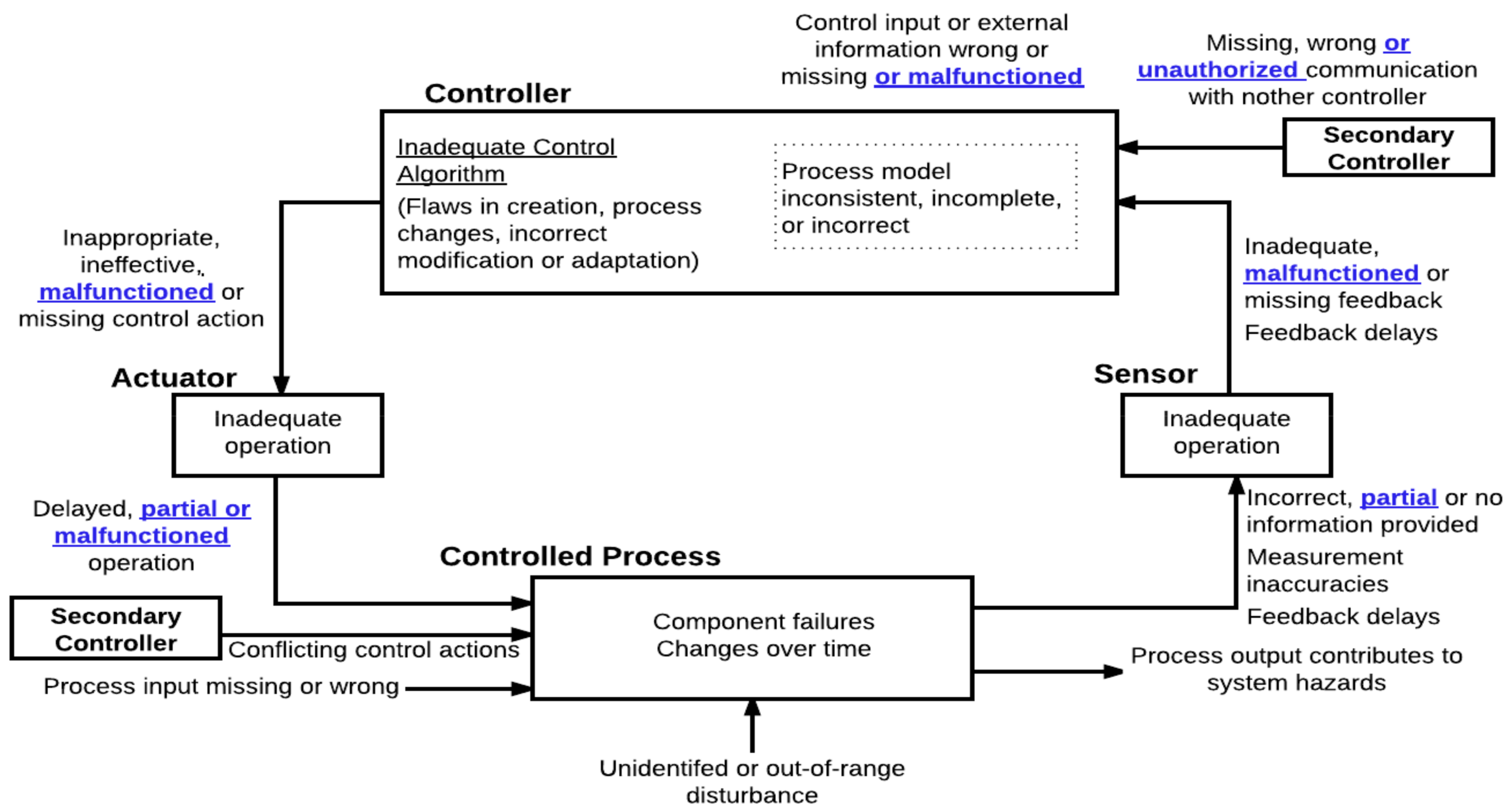
2.3. Stage 2: Identify Potentially Unsafe/Unsecure Control Actions: Functional Control Structure

Our analysis focuses on the over-the-air (OTA) software updates, a key capability which enables the connected autonomous vehicle to exchange live updates such as traffic/road conditions, routing instructions, and location updates, as well as periodic firmware updates and bug fixes. The ability to receive OTA software updates is key to realizing the MaaS concept, but it also poses a different range of attack surfaces that can be exploited.
Figure 8 shows the high-level functional control structure of socio-technical components in the OTA software updates example. The functional control structure details the control loops within the system, together with interactions among components at different hierarchical levels. This functional control structure provides the basis to further analyze safety and security constraints within the system. The system boundary under analysis in this study is represented by components in the shaded box. Although the analysis is limited to components within the system boundary, it is important to consider interactions with external sociotechnical systems to glean additional insights and context to the analysis.

2.4. Unsafe/Unsecure Control Actions

The next step is to identify unsafe/unsecure control actions by assessing control loops within the functional control structure. This analysis is not limited to electromechanical components; they can be used to analyze organizational or management components within the control structure. Four types of unsafe control action that can lead to a hazardous outcome are considered, namely:
  • A control action required for safety is not provided;
  • An unsafe/unsecure control action is provided that leads to a hazard;
  • A potentially safe control action is provided too late, too early, or out of sequence;
  • A safe control action is stopped too soon or applied too long.
Based on the four types of UCAs described above, this stage seeks to identify actions that may cause the system to reach a hazardous state. A total of 15 UCAs were generated by considering each interaction in the functional control. For brevity, only seven examples are provided in Table 2. Starting from the interactions between the control center and the AVs, three UCAs were identified. UCA-11 identifies a case where unauthorized updates are provided to the AV, potentially leading to hazards H1 (adversaries take over control of safety-critical features of AV) and H2 (AV operating with unsafe/unsecure/outdated software). UCA 10 and 12 identify cases where software updates are not applied to the AVs, or not applied in timely manner, leading to the same hazards H1 and H2.
For each identified UCA, Safety and Security Constraints (SSCs) were recommended at component-level. Table 3 shows examples of SSCs. These SSCs are high-level requirements and could serve as input for safety/security features and requirements as part of the guided design process.
The high-level safety/security constraints derived from the analysis up to stage 2 may be sufficient for some analysis. In stage 3, we select a few UCAs for further analysis to identify scenarios and causal factors which may cause the UCAs to occur.

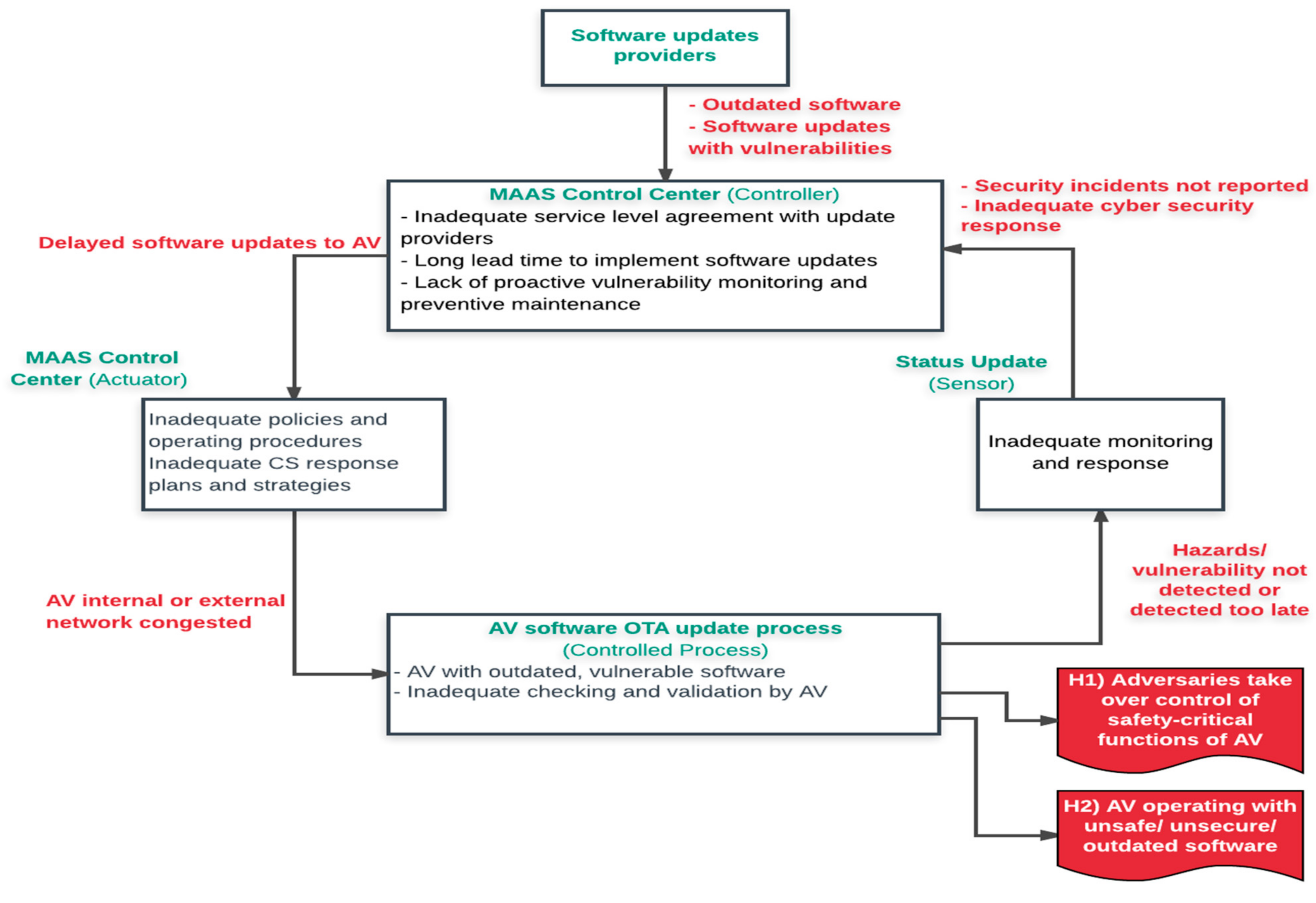
2.5. Stage 3: Identify Causes for Unsafe/Unsecure Control Actions and Propose Mitigation Measures

Stage 3 aims to identify possible scenarios where unsafe/unsecure control actions may occur. This enables us to map out how unsafe control actions may be triggered, facilitating recommendation of safety and security requirements and improvements to system design, organizations policies, or security governance framework. Cybersafety provides a method to systematically identify possible causes for each identified UCAs. Using the classification of potential control loop disruptions described in Figure 9, we analyzed control loops to identify hazardous scenarios and causal factors that may lead to violation of any safety or security constraints. The diagram includes considerations (underlined and bolded) to include security analysis. For example, the communication between the main controller and secondary controller also includes unauthorized communications (in additional to missing or wrong communications) when we include cybersecurity considerations in our analysis. The control loop analysis provides heuristics to identify potential disruptions that may cause the system to reach a hazardous or vulnerable state.

2.6. Interactions between MaaS Control Center and AVs

This example demonstrates the analysis of process models to investigate scenarios and causal factors leading to unsafe/unsecure interactions between the MaaS control center and the autonomous vehicles (see Figure 10). Starting from the top, software update providers issue software updates to the MaaS control center. To control the distribution of software updates, the control center’s process model considers the type of software update (periodic or dynamic), criticality of software update, update mechanisms, and target AVs to be updated. The update process is managed by the OTA software update management system, which distributes approved software updates. Once the updates are downloaded to the AVs, the software packages are installed, and the update progress are feedback to the control center.
The process model is a crucial step to help us understand why accidents occur. In the stable state, the controllers, actuators, and feedback mechanism ensure the safe and secure operation of software updates process. Using the generic causal factors shown in Figure 9 as a guide, potential scenarios for unsafe interactions and their causal factors were identified. The graphical representation of scenarios and causal factors of unsafe interactions are shown in Figure 11. Working around the loop, causal factors for each of the components are shown in boxes representing the controller, actuator, control process, and sensors. The detailed scenarios, causal factors, and recommended safety/security requirements are generated in further details as shown in Table 4.

3. Results: Summary of Cybersafety Analysis

The cybersafety coanalysis of safety and security hazards with the MaaS software OTA update use case demonstrated several potential benefits over traditional methods. Adopting systems thinking approach and analyzing hazards using control theory provides guidance to consider the broader system. Furthermore, the approach facilitates the identification of hazardous states due to unsafe/unsecure interactions among components and readily captures causal factors such as managerial decisions, organizational policies, and regulatory landscape arising from sociotechnical interactions. The full analysis (refer to [28]) yielded 44 design requirements. From a systems-control perspective, these requirements aim to mitigate safety and security risks by controlling feedback loops in order to prevent the system from reaching the hazardous states as defined earlier in this chapter.
The key findings and takeaways from the cybersafety analysis are summarized as follow:
  • Based on a top-down approach, its scope of analysis is bounded by unacceptable accidents/losses and hazards identified upfront. One key lesson from this study is that even for a relatively narrow system boundary under analysis, the number of causal scenarios, and mitigation actions can expand substantially. It is therefore recommended to begin the analysis at higher levels of abstraction and then go into further details by further in-zooming the functional control structure in subsequent iterations.
  • One of the distinguishing features of this approach is the consideration of sociotechnical interactions beyond the technical operational aspects of the system. Analyzing the interactions within the whole ecosystem can be useful in finding insights on how the external interactions may impact process model of components further down the control structure.
  • Incorporating heuristics could aid the identification of unsafe/unsecure interactions, as well as causal scenarios in which such interactions may take place. In Stage 2, the four factors in which unsafe control actions can take place (e.g., control action not provided, unsafe/unsecure control action provided, control action provided too late/too early/out of sequence, and control action stopped too soon or applied too long) are to some extend similar to HAZOP guidewords. In Stage 3, in addition to classification of causal factors for identifying possible accident scenarios, it may be useful to apply the Confidentiality, Integrity, and Availability (“CIA”) guidewords as creativity process for identifying cybersecurity causal factors.
  • An additional benefit is the ability to trace mitigation requirements to the hazard(s) that these requirements are intended to mitigate against. Having clear traceability to the intent is important to help developers and testers validate the system, as well as ensure that the mitigation measures are maintained should the system be upgraded or replaced.

3.1. Comparison between Cybersafety and Combined Harm Analysis of Safety and Security for Information Systems (CHASSIS)

In the preceding section, we identified causal factors and scenarios by using heuristics in Figure 9 to identify causal factors and scenarios in which UCAs can occur. While this approach was effective in generating unique and important considerations as part of the stage 3 analysis, other methods may also be used to complement and add additional considerations. In the 2016 STAMP conference [27], Young proposed the use of information lifecycle model to add considerations to the STPA-Sec analysis (see Figure 12).
To this end, in [28] a Combined Harm Analysis of Safety and Security for Information Systems (CHASSIS) analysis was conducted. This section compares the recommended mitigations from both CHASSIS and cybersafety analyses and list additional mitigations generated if we were to incorporate information lifecycle stages to generate additional considerations.
Table 5 compares the number of requirements for each category generated from both cybersafety and CHASSIS. Across all categories, it is observed that more requirements were generated from cybersafety analysis.
A qualitative comparison of both hazards analysis methods is provided in Table 6. Based on the comparison of analysis results, there are strengths in CHASSIS analysis that makes it feasible to complement cybersafety stage 3 analysis to generate additional considerations. In particular, we found that because CHASSIS focuses on possible activities by misusers and attackers at various stages of information lifecycle, the analysis generated layered defense requirements with specific prevention and detection mechanisms at key components to prevent propagation of vulnerabilities. The information lifecycle analysis (using CHASSIS models) could be conducted in subsequent stages of cybersafety to derive additional requirements at components level.
The comparisons between cybersafety and CHASSIS are shown below. Several differences which may affect its effectiveness in specific context are highlighted.

3.2. Analysis Approach

Both methods encompass coanalysis of safety and security hazards. At its core, cybersafety is built on control theory with hazards and vulnerabilities a result of inadequate controls within the system. As a result, the technique enables identification of unsafe interactions even if individual components are working perfectly. On the other hand, CHASSIS model system behavior is based on information flow and interactions; it facilitates identification of system failures or vulnerabilities based on activities introduced by misusers or attackers. We also observed that for analysis at high-level abstractions, in-depth knowledge of the system is not a necessity, which makes both methods feasible for teams without strong expertise in the system.

3.3. Level of Abstraction

Cybersafety’s concept is to analyze the system taken as a whole, rather than its components taken separately and is a high-level, top-down approach, focusing on emergent properties that arise from relationships among components. Therefore, the technique is well suited for systems in early stages of development and concept phase where architectural artefacts have not been established. Cybersafety generates more high-level requirements considering the larger sociotechnical aspects of the system. In contrast, CHASSIS can be considered a bottom-up approach building upon functional decomposition of key components use cases and their interactions. To establish the use cases and information sequence flow of the system, some high-level functional requirements and information transactions would be required during analysis. The mitigations generated by CHASSIS are strong in generating layered defense against possible activities by misusers and attackers to prevent the vulnerability/fault from propagating through the system.

3.4. Scope of Analysis

Cybersafety first establishes the high-level control structure encompassing sociotechnical interactions with components of the system. The system boundary is then defined to set the focus of analysis on components that are within the team’s influence. Next, definition of unacceptable losses/accidents and hazards also narrow down identification of unsafe control actions to those that attribute to the hazards. In this research, it is common to see the scope of analysis can expand, especially in stages 2 and 3. Therefore, it is worthwhile to consider starting with a high-level abstraction for the control structure and unacceptable losses/accidents and then proceed with more in-depth analysis in later stages of analysis.
One of the key features of CHASSIS is the use of UML to model system interactions using use-case/misuse-case diagrams and sequence diagrams. These artefacts may be extended from system design documentations to include system flaws and vulnerabilities that may lead to harm. Furthermore, the diagrammatic UML representations provides a key strength of CHASSIS as these representations of system interactions are intuitive and can easily be conveyed to key stakeholders during discussions. Although CHASSIS have not been designed to consider external organizational and environmental interactions, it is possible to expand the boundary in subsequent iterations, as demonstrated where the interactions between the management team and control center was expanded to the risk scenario considerations.

4. Discussion: Backtesting against A Past Cyber Hack Scenario

Case Analysis of Recommendations from Cybersafety

Next, we evaluate effectiveness of the list of recommendations generated from our cybersafety analysis by backtesting against a past cyber hack scenario. In a series of hacks starting in 2013, Miller and Valasek demonstrated how potential hackers can gain access to vehicles over the Internet. The experiment, conducted on various car models including the Jeep Cherokee, Toyota Prius, and Ford Escape, demonstrated the ability to remotely control the vehicle’s fan, music volume, wipers, and even safety-critical features such as the steering wheels, accelerators, and brakes [29]. The generic system architecture of the Jeep Cherokee is shown in Figure 13.
Millier and Valasek identified several vulnerabilities which enabled them to gain access to the vehicle’s safety-critical features. There has been some confusion as to whether physical access to the vehicle was required. Although physical access to one such vehicle might have been needed to determine the details, the actual cyber attack was conducted remotely without any physical access to the vehicle being attacked). The vulnerabilities are depicted in Figure 14 and summarized as follows:
  • The researchers identified a microcontroller and software within the UConnect head unit that connects to other components of the vehicle through the vehicle’s internal network known as the Controller Area Network (CAN) bus. The CAN bus is a critical infrastructure that enable communications among the vehicle’s electronic control units. Others that have looked at concerns and vulnerabilities related to the CAN include [30,31]. (Some papers have focused on vehicle sensors, such as [32].)
  • Using this as an entry point, Miller and Velasek planted their code on the firmware of an entertainment system hardware, disabling checks and balances in the vehicle computer units, and enabling them to send commands to the vehicle’s CAN bus.
  • To access the vehicular network wirelessly using WiFi, the researchers identified that each vehicle’s WPA password was generated based on the epoch time (in seconds) from the time the vehicle was manufactured to the first start-up. The researchers were able to narrow down to a few dozen combinations, and the WPA password used to access the vehicle network could be guessed quite easily.
  • The UConnect system uses Sprint’s 3G network to communicate with other vehicles, and with the vehicle manufacturer for software updates. The researchers found that it was possible to communicate with other Sprint devices connected anywhere in the country. This network vulnerability allowed the researchers to increase their range of attack by exploiting cellular access into the vehicle.
Using the cybersafety method, an analysis was conducted to analyze deficiencies in the control structure of the Jeep Cherokee case. The goal of this analysis is to identify how system constraints were violated leading to the successful hacks by Miller and Valasek. The accidents/losses, system hazards, and system constraint associated with this incident is shown below.
Associated accidents/losses:
A1: Financial loss to manufacturer due to recall and rectification of vulnerability
A2: Loss of reputation for manufacturer
A3: Loss of consumer confidence in smart vehicles
Associated system hazard:
H1: Attacker gain access to vehicle to load malicious software [A1, A2, A3]
H2: Attacker gain control of safety-critical functions of vehicle [A1, A2, A3]
Associated system constraint:
SC1: The system control structure must prevent unauthorized software from being loaded to vehicle [H1]
SC2: The system control structure must prevent unauthorized control over safety-critical functions of vehicle [H2]
Figure 15 shows the generic control structure of the vehicle with infotainment controller unit similar to Jeep Cherokee’s UConnect feature. The feature allows the human operator (driver) to access and control infotainment features of the vehicles through on-board UConnect Dashboard. The UConnect infotainment system also acts as the visual interface between the driver and vehicular ECUs (such as entertainment system). Vehicular features such as software updates, navigation, telematics, entertainment, and connectivity are available through the vehicle’s UConnect feature. The control structure is extended to include the manufacturer, which may receive software update requests following authorization by the human operator. The manufacturer has the capability to provide software updates to the vehicle over the air.
Table 7, Table 8 and Table 9 provide an analysis of safety/security constraints violated in each component, together with any emergency and safety equipment present, physical failures, and inadequate controls, as well as contextual factors:
  • At the physical system (vehicle) level, the unauthorized control of vehicle’s safety-critical components results in violation of safety/security constraint. The driver is also unable to safely override or takeover control of the vehicle. Based on the analysis, the physical failure or inadequate control that led to the violation are due to the Electronic Control Unit (ECU) executing unauthorized command, as well as indirect linkages in ECUs performing safety-critical functions and infotainment functions.
  • For the in-car controller, the safety/security constraints violated include the transmission and execution of unauthorized commands and the unauthorized access to the vehicle’s safety-critical features. A number of inadequate controls were observed, ranging from nonencrypted messages, inadequate authorization, and authentication mechanisms, and availability of a back door for attackers to insert malicious codes.
  • For the vehicle manufacturer, possible safety/security constraints include inadequate secure development process, cyber-security-related competencies, and quality-assurance processes to ensure cybersecurity risks are mitigated. It is also important to consider contextual factors, such as the supply of parts from different manufacturers, and the competitive industry that calls for new features that may lead to new attack surfaces.
Understanding of contextual factors helps us consider external conditions and systemic factors that result in the inadequate controls or unsafe decisions. For instance, based on the analysis of physical failures and inadequate controls, one may be tempted to conclude that the root causes for vulnerabilities were due to poor engineering design which allowed the attackers to access the vehicle’s CAN bus indirectly through the infotainment system. Another possible root cause could be due to inadequate transmission and data protection to prevent the system from receiving and executing unauthorized commands. To look beyond human flaws and design errors, it is helpful to consider other factors such as emergency and safety equipment controls that may not have worked during the accident, as well as contextual factors leading to how existing controls were not effective in preventing the accident.
The in-depth analysis identified several additional unsafe interactions such as:
  • Inadequate control for driver to override or takeover control of vehicle when vehicle is compromised by attacker
  • Unsafe/unsecure interactions between remote-accessible infotainment system and CAN bus connected to safety-critical features can lead to security vulnerability
  • Lack of feedback to alert the driver or manufacturer when the vehicle’s safety and security features were compromised. Possible points of compromise include jailbreaking the UConnect console to enable unauthorized software updates, installation of unauthorized software updates, or suspicious access into the system to alter safety-critical features of the vehicle.
Additionally, by extending the control structure to higher hierarchical levels, more in-depth analysis was conducted to analyze contributions of managerial and organizational factors to the vehicle’s vulnerabilities:
  • Awareness and technical competencies of staff in vehicular cybersecurity
  • Effect of competition and time to market on security test adequacy
  • Effect of the lack of standards and regulations on cybersecurity in the automotive industry
  • Adequacy of cybersecurity activities (design, build, and test) in the automotive development approach
  • Adequacy of training and resources allocated to cybersecurity efforts in the organization
The unsafe and unsecure interactions identified from the research are represented in the updated control structure found in Figure 16 (boxes and lines in red represent the unsafe/unsecure interactions). Some inadequate controls and feedback were identified which enabled the researchers to identify vulnerabilities and gain access into the system. Some critical control loops not present in the initial control structure were identified. For instance, vulnerabilities in the cellular network access allowed the researchers to identify Internet of Things (IoT) devices connected within the Sprint network. While it may not be clear whether the network service provider is responsible for securing communications to IoT devices connected to their network, it is a clear indication on the importance to consider network service providers in security risk analysis and to ensure that cybersecurity responsibilities of key parties in the supply chain are clearly defined and executed.
Table 10 summarizes the inadequate controls and unsafe decisions identified from this simplified cybersafety analysis. Requirements generated from both the cybersafety and CHASSIS analysis (discussed in the earlier sections) that may mitigate these inadequate controls and unsafe decisions are included in the table. We observe that all identified inadequate controls and unsafe decisions are mapped to at least one high-level mitigation measure from cybersafety. In contrast, mitigation measures from CHASSIS analysis did not cover some of the identified inadequate controls and unsafe decisions identified in this analysis. It is worthwhile to note that there are differences between the two cases studied: OTA software update on autonomous vehicles and cyber hack on a connected vehicle platform (UConnect). Despite the differences, the high-level analysis approach in cybersafety is able to generate broad requirements that cover both cases. Although this does not guarantee that this cyber hack would not have been possible if the manufacturer had followed all requirements generated from our analysis, it would be able to address some of the loopholes identified by the researchers, making the hacks more difficult.

5. Conclusions

This research presented the application of a new safety and security coanalysis, cybersafety, inspired by the STAMP approach, which is premised on viewing safety and security as control issues (rather than reliability problems). The results were compared with another safety and security coanalysis method, CHASSIS, which is built on existing safety and security concepts and information flows to represent both use cases and misuse cases.
Applying cybersafety to the MaaS OTA software update case, the analysis identified several unique and important causal factors and mitigation requirements not identified under CHASSIS analysis. The key strengths of cybersafety include the ability to identify unsafe interactions among components that may lead the system to hazardous state and considerations of sociotechnical interactions beyond the technical aspects of the system. Overall, cybersafety generated more requirements that have greater impact on addressing control weaknesses in the system and demonstrated its ability to identify control flaws which may be missed in traditional hazards analysis methods. Some strengths in CHASSIS analysis were identified, and it was proposed to complement CHASSIS for information lifecycle analysis to generate additional considerations analysis in cybersafety stage 3.
Finally, the mitigation requirements from both methods were evaluated by backtesting against a past cyber hack scenario involving the remote hack experiment on the Jeep Cherokee. Using a simplified cybersafety analysis, inadequate controls and unsafe decisions from the cyber hack scenario were generated, and mitigation requirements were assessed. Cybersafety generated requirements that were mapped to all inadequate controls and unsafe decisions identified in the analysis. In contrast, mitigation requirements from CHASSIS analysis did not address some of the inadequate controls and unsafe decisions identified in the Jeep Cherokee case.
Overall, this research on using the cybersafety method should serve to encourage its further exploration, particularly in the automotive domain. Although inherent cybersecurity risks will continue to exist with new features and technologies introduced to vehicles, it is possible to mitigate most of the risks by adopting a holistic, top-down approach and considering sociotechnical interactions within the system.

Author Contributions

Conceptualization and methodology: C.W.L. and S.M.; formal analysis, investigation, original draft preparation, C.W.L.; review and editing, supervision, C.W.L. and S.M. All authors have read and agreed to the published version of the manuscript. Please turn to the CRediT taxonomy for the term explanation.

Funding

This work was supported, in part, by cybersecurity at MIT Sloan (CAMS): The Interdisciplinary Consortium for Improving Critical Infrastructure Cybersecurity, (IC)3.

Data Availability Statement

All data used in this paper is reported in this paper or is available from the References Cited.

Conflicts of Interest

The authors declare no conflict of interest.

References

  1. Keeney, T. Mobility-as-a-Service: Why Self-Driving Cars Could Change Everything. ARK Invest. Available online: https://research.ark-invest.com/self-driving-cars-white-paper (accessed on 17 June 2017).
  2. Lee, E. Mobility as a Service Market Size worth USD 523.61 Billion by 2027. Emergen Research. 14 December 2020. Available online: https://www.globenewswire.com/news-release/2020/12/14/2144252/0/en/Mobility-as-a-Service-Market-Size-Worth-USD-523-61-Billion-by-2027-Emergen-Research.html (accessed on 21 September 2017).
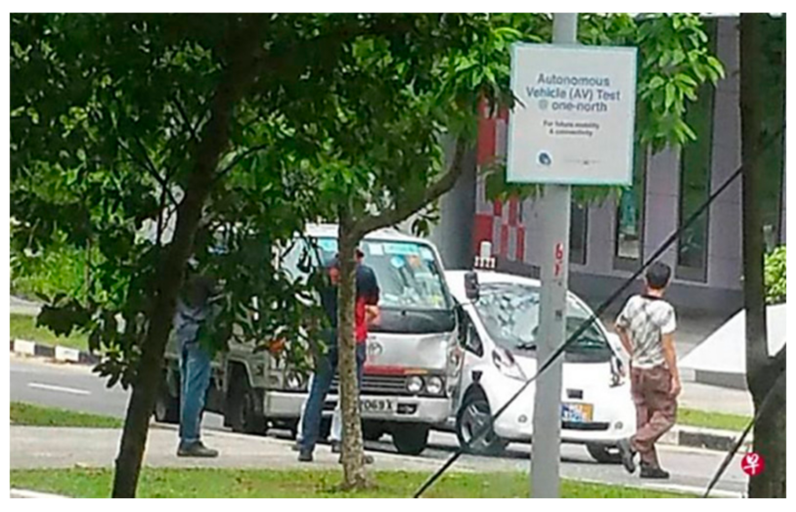
  3. Weilun, S. nuTonomy Driverless-Car Accident due to ‘Extremely Rare’ Software Glitches: One-North Trial Resumes. The Business Times. Available online: http://www.businesstimes.com.sg/transport/nutonomy-driverless-car-accident-due-to-extremely-rare-software-glitches-one-north-trial (accessed on 29 October 2017).
  4. Golson, J. Tesla and Mobileye Disagree on Lack of Emergency Braking in Deadly Autopilot Crash. The Verge. 1 July 2016. Available online: https://www.theverge.com/2016/7/1/12085218/tesla-autopilot-crash-investigation-radar-automatic-emergency-braking (accessed on 21 September 2017).
  5. Controlling Vehicle Features of Nissan LEAFs across the Globe via Vulnerable APIs. Troy Hunt. 24 February 2016. Available online: https://www.troyhunt.com/controlling-vehicle-features-of-nissan/ (accessed on 21 July 2017).
  6. Hackers Remotely Kill a Jeep on the Highway—With Me in It. WIRED. Available online: https://www.wired.com/2015/07/hackers-remotely-kill-jeep-highway/ (accessed on 5 September 2017).
  7. Automotive Security (ASQ). Challenges, Standards, and Solutions; ASQ: Milwaukee, WI, USA, 2016. [Google Scholar]
  8. Leveson, N.G. Engineering a Safer World: Systems thinking Applied to Safety; The MIT Press: Cambridge, MA, USA, 2012. [Google Scholar]
  9. J1739: Potential Failure Mode and Effects Analysis in Design (Design FMEA) and Potential Failure Mode and Effects Analysis in Manufacturing and Assembly Processes (Process FMEA) and Effects Analysis for Machinery (Machinery FMEA); SAE International: Warrendale, PA, USA. Available online: http://standards.sae.org/j1739_200208/ (accessed on 1 September 2017).
  10. Ericson, C.A., II. Fault Tree Analysis Primer, 2nd ed.; CreateSpace Independent Publishing Platform: Scotts Valley, CA, USA, 2011. [Google Scholar]
  11. Banerjee, A.; Venkatasubramanian, K.K.; Mukherjee, T.; Gupta, S.K.S. Ensuring Safety, Security, and Sustainability of Mission-Critical Cyber—Physical Systems. Proc. IEEE 2012, 100, 283–299. [Google Scholar] [CrossRef]
  12. Schneider, D.; Armengaud, E.; Schoitsch, E. Towards Trust Assurance and Certification in Cyber-Physical Systems. In Computer Safety, Reliability, and Security; Springer: Cham, Switzerland, 2014; pp. 180–191. [Google Scholar]
  13. Macher, G.; Sporer, H.; Berlach, R.; Armengaud, E.; Kreiner, C. SAHARA: A security-aware hazard and risk analysis method. In Proceedings of the 2015 Design, Automation Test in Europe Conference Exhibition (DATE), Grenoble, France, 9–13 March 2015; pp. 621–624. [Google Scholar]
  14. Security Application of Failure Mode and Effect Analysis (FMEA) | SpringerLink. Available online: https://link.springer.com/chapter/10.1007/978-3-319-10506-2_21 (accessed on 19 August 2017).
  15. Raspotnig, C.; Karpati, P.; Katta, V. A Combined Process for Elicitation and Analysis of Safety and Security Requirements. In Enterprise, Business-Process and Information Systems Modeling; Springer: Berlin/Heidelberg, Germany, 2012; pp. 347–361. [Google Scholar]
  16. Dominic, D.; Chhawri, S.; Eustice, R.M.; Ma, D.; Weimerskirch, A. Risk Assessment for Cooperative Automated Driving. In Proceedings of the 2nd ACM Workshop on Cyber-Physical Systems Security and Privacy, New York, NY, USA, 16 October 2016; pp. 47–58. [Google Scholar]
  17. Martinez, R.S. System Theoretic Process Analysis of Electric Power Steering for Automotive Applications. Master’s Thesis, Massachusetts Institute of Technology, Engineering Systems Division, Cambridge, MA, USA, June 2015. [Google Scholar]
  18. Peper, N.A. Systems Thinking Applied to Automation and Workplace Safety. Master’s Thesis, Massachusetts Institute of Technology, Cambridge, MA, USA, June 2017. [Google Scholar]
  19. Fleming, C.H.; Leveson, N.G. Improving Hazard Analysis and Certification of Integrated Modular Avionics. J. Aerosp. Inf. Syst. 2014, 11, 397–411. [Google Scholar] [CrossRef] [Green Version]
  20. Pawlicki, T.; Samost, A.; Brown, D.W.; Manger, R.P.; Kim, G.Y.; Leveson, N.G. Application of systems and control theory-based hazard analysis to radiation oncology. J. Med. Phys. 2016, 43, 1514–1530. [Google Scholar] [CrossRef] [PubMed]
  21. Young, W.; Leveson, N.G. An Integrated Approach to Safety and Security Based on Systems Theory. Commun. ACM 2014, 57, 31–35. [Google Scholar] [CrossRef]
  22. Salim, H. Cybersafety: A Systems Thinking and Systems Theory Approach to Managing Cyber Security Risks. Master’s Thesis, Engineering Systems Division, Massachusetts Institute of Technology, Cambridge, MA, USA, 2014. [Google Scholar]
  23. Young, W.; Leveson, N. Systems thinking for safety and security. In Proceedings of the 29th Annual Computer Security Applications Conference (ACSAC ’13 ACM), New Orleans, LA, USA, 16 December 2013. [Google Scholar]
  24. Salim, H.; Madnick, S. Cyber Safety: A Systems Theory Approach to Managing Cyber Security Risks—Applied to TJX Cyber Attack. Working Paper CISL 2016-09. August 2016. Available online: http://web.mit.edu/smadnick/www/wp/2016-09.pdf (accessed on 3 April 2021).
  25. Nourian, A.; Madnick, S. A Systems Theoretic Approach to the Security Threats in Cyber Physical Systems Applied to Stuxnet; Working Paper CISL 2014-13; September 2014. [Google Scholar] [CrossRef] [Green Version]
  26. Nourian, A.; Madnick, S. A Systems Theoretic Approach to the Security Threats in Cyber Physical Systems Applied to Stuxnet. IEEE Trans. Dependable Secur. Comput. 2018, 15, 2–13. [Google Scholar] [CrossRef] [Green Version]
  27. Young, W., Jr. Understanding STPA-Sec through a Simple Roller Coaster Example. In Proceedings of the 2016 STAMP Conference, Boston, MA, USA, 23 March 2016. [Google Scholar]
  28. Lee, C.W. A System Theoretic Approach to Cybersecurity Risks Analysis of Passenger Autonomous Vehicles. Master’s Thesis, Massachusetts Institute of Technology, Cambridge, MA, USA, February 2018. [Google Scholar]
  29. Valasek, C.; Millier, C. Remote Exploitation of an Unaltered Passenger Vehicle. Available online: http://illmatics.com/Remote%20Car%20Hacking.pdf (accessed on 7 May 2015).
  30. Casillo, M.; Coppola, S.; De Santo, M.; Pascale, F. Emanuele Santonicola Embedded Intrusion Detection System for Detecting Attacks overCAN-BUS. In Proceedings of the 2019 4th International Conference on System Reliability and Safety (ICSRS), Rome, Italy, 20–22 November 2019; pp. 136–141. [Google Scholar] [CrossRef]
  31. Castiglione, A.; Palmieri, F.; Colace, F.; Lombardi, M.; Santaniello, D.; D’Aniello, G. Securing the Internet of vehicles through lightweight block ciphers. Pattern Recognit. Lett. 2020, 135, 264–270. [Google Scholar] [CrossRef]
  32. El-Rewini, Z.; Sadatsharan, K.; Sugunaraj, N.; Selvaraj, D.F.; Plathottam, S.J.; Ranganathan, P. Cybersecurity Attacks in Vehicular Sensors. IEEE Sens. J. 2020, 20, 13752–13767. [Google Scholar] [CrossRef]
Figure 1. Global revenue for autonomous cars and services [1].
Electronics 10 01220 g001
Figure 2. Generic architecture for connected autonomous vehicles in MaaS.
Electronics 10 01220 g002
Figure 3. Minor accident involving nuTonomy AV in Singapore.
Electronics 10 01220 g003
Figure 4. Fatal accident involving Tesla semiautonomous vehicle in Florida.
Electronics 10 01220 g004
Figure 5. Remote car-jacking of Jeep Cherokee.
Electronics 10 01220 g005
Figure 6. Example threat matrix visualization for driverless parking example [15].
Electronics 10 01220 g006
Figure 7. Leveson’s general control structure of a sociotechnical control structure [7].
Electronics 10 01220 g007
Figure 8. Functional control structure for software OTA updates.
Electronics 10 01220 g008
Figure 9. Potential control loop disruptions leading to hazardous states (adapted from [27]).
Electronics 10 01220 g009
Figure 10. Process model for periodic/dynamic software updates to AVs.
Electronics 10 01220 g010
Figure 11. Causal scenarios analysis for periodic/dynamic software updates to AVs.
Electronics 10 01220 g011
Figure 12. Information lifecycle stages [27].
Electronics 10 01220 g012
Figure 13. Generic system architecture and features of the Jeep Cherokee.
Electronics 10 01220 g013
Figure 14. Key vulnerabilities of the Jeep Cherokee.
Electronics 10 01220 g014
Figure 15. Generic control structure of the Jeep Cherokee system under analysis.
Electronics 10 01220 g015
Figure 16. Revised control structure representing unsafe/unsecure interactions identified from research.
Electronics 10 01220 g016
Table 1. Hazards and associated accidents/losses.
HazardsAssociated Accidents/Losses
H1: Adversaries take over control of safety-critical functions of AVA1, A2, A3
H2: AV operating with unsafe/unsecure/outdated softwareA1, A2, A3
H3: Adversaries compromise network/critical infrastructure supporting AV A3, A4
H4: AV traveling on unsafe/unauthorized road A1, A2
Table 2. Potentially unsafe/unsecure control actions.
Control ActionNot Providing Causes HazardProviding Causes HazardToo Early/Too Late/Wrong Order Causes HazardStopping Too Soon/Applying Too Long Causes Hazard
UCAs between MaaS Operator (Management) and software update provider
Service agreementUCA-1: Service agreement with network provider not provided before system is operationalized [H3, H4]Not hazardousNot applicableNot applicable
UCAs between MaaS Operator (Management) and Control Center
Safety/security policies and operating procedureUCA-3: Safety policies and operating procedure not provided before system is operationalized [H1–H4]Not hazardousNot applicableNot applicable
UCAs between software update providers and Control Center
Periodic software updatesUCA-7: Software updates not provided by providers when new threats/vulnerabilities exist [H1, H2]Not hazardousUCA-8: Software updates provided too late by providers when new threats/vulnerabilities exist [H1, H2]Not applicable
UCAs between Control Center and AV
Periodic/dynamic software updatesUCA-10: Software updates not applied to AVs when threats or vulnerabilities exists in AV [H1, H2]UCA-11: Unauthorized software updated into AVs [H1, H2, H4]UCA-12: Software update not applied to AVs in timely manner when threats or vulnerabilities exists in AV [H1, H2, H4]Not applicable
Table 3. Extracts of safety/security constraints.
Unsafe/Unsecure Control ActionsPossible Safety/Security Constraints
UCA-1: Service agreement with network provider not provided before system is operationalized [H3, H4]SC-1: The MaaS operator shall establish service level agreement with network service provider to ensure adequate coverage of network, availability, and protection levels against cyber security threats.
UCA-3: Safety policies and operating procedure not provided before system is operationalized [H1–H4]SC-2: The MaaS operator shall translate applicable regulatory requirements and standards to safety policies and operating procedures.
UCA-7: Software updates not provided by providers when new threats/vulnerabilities exist [H1, H2]SC-7: The MaaS operator shall establish protocols for periodic or ad-hoc software updates upon detection of vulnerabilities.
UCA-8: Software updates provided too late by providers when new threats/vulnerabilities exist [H1, H2]SC-3: The MaaS operator shall establish protocols for timely update of critical software updates that need to be installed on AVs expeditiously
UCA-10: Software updates not applied to AVs when threats or vulnerabilities exists in AV [H1, H2]SC-10: The MaaS operator shall, by working with associated providers, ensure that software updates are provided to provide fixes for detected vulnerabilities.
UCA-11: Unauthorized software updated into AVs [H1, H2, H4]SC-11: The MaaS operator shall, by working with relevant parties, prevent unauthorized software from being installed into AVs.
UCA-12: Software update not applied to AVs in timely manner when threats or vulnerabilities exists in AV [H1, H2, H4]SC-12: The MaaS operator shall ensure timely response to vulnerable software by providing fixes/patches through pre-emptive or quick recovery approach
Table 4. STPA Stage 3 analysis results for periodic/dynamics software updates to AV.
ScenarioAssociated Causal FactorsRequirements/Design FeaturesAllocated toRationale
UCA-7: Software updates not provided by providers when new threats/vulnerabilities exist [H1, H2]
UCA-8: Software updates provided too late by providers when new threats/vulnerabilities exist [H1, H2]
Outdated software
Software updates with vulnerabilities
Inadequate service level agreement with update providersR-1: Establish service level agreement with update providers to ensure preventive bugs and vulnerability fixes are includedMaaS Operator (Management team)Improve organizational cybersecurity plans and strategies
Long lead time to implement software updatesR-2: Ensure proactive vulnerability monitoring. For example, bug bounty program to invite “ethical hackers” to find security vulnerabilities
R-3: Dedicated, independent cyber security team actively looking into regular security audit tests and detecting any new threats/vulnerabilities.
MaaS Operator (Management team)Improve organizational cybersecurity plans and strategies
Lack of proactive vulnerability monitoring and security maintenance
UCA-10: Software updates not applied to AVs when threats or vulnerabilities exists in AV [H1, H2]
UCA-12: Software update not applied to AVs in timely manner when threats or vulnerabilities exists in AV [H1, H2, H4]
Delayed software updates to AVsInadequate policies and operating proceduresR-4: Develop cybersecurity policies and operating procedures to determine update lead time based on different levels criticality.MaaS Operator (Management team)Improve organizational cybersecurity plans and strategies
Inadequate cybersecurity response plans and strategiesR-5: Develop cybersecurity response plans and strategies, ensuring all parties involved know their roles and responsibilities in the event of cyber-attack (malicious software updates)
R-6: Provide a system for response plans to be exercised and lessons learnt incorporated to improve existing plans
MaaS Operator (Management team)Improve organizational cybersecurity plans and strategies
AV internal or external network over-loadedExcessive traffic restricting software updates to AVR-7: AV gateway designed to prevent unauthorized trafficMaaS IT Infra/security teamImproving critical infraprotection
File size of software updates too largeR-8: MaaS operator to work with providers to limit file size of software updatesMaaS OperatorCoordination and cooperation with external providers
Too many concurrent downloadsR-9: MaaS operator to stagger software updates in to minimize network congestionMaaS OperatorEnhancing internal policies and procedures
Backdoor attacks within vehicular network (CAN bus)R-10: Segregate networks for safety-critical functions and non-safety-critical functionsAV ManufacturerImproving AV security design
Table 5. Comparison of recommended mitigation measure types between STPA-Sec and CHASSIS.
Categories of RequirementsCybersafetyCHASSIS
Managerial aspects72
Organizational/operations aspects147
Technical (AV design) aspects1310
Technical (MaaS IT Infrastructure) aspects144
Total requirements4823
Table 6. Qualitative comparison of recommended mitigations from STPA-Sec and CHASSIS.
Mitigations in Both Cybersafety and CHASSISMitigations in Cybersafety OnlyMitigations in CHASSIS Only
Both methods identified mitigations to strengthen control and protection at key components under system boundary.
-
Strength in identifying mitigations from sociotechnical aspects that have indirect interactions with technical system (considered investors, standards and regulations, staff training and competency, environmental impacts, etc.).
-
Significantly more requirements from managerial, organizational policies/processes; more focus on top-down control mechanisms than bottom-up fixes.
-
Strength in identifying layered defense; specific prevention and detection requirements for each component within information chain.
-
Focused on possible activities by misusers and attackers
-
Unique requirements include: identification of wrong or outdated software updates due to human error; tamper-proof design for critical features to mitigate attackers’ activities
Table 7. Analysis of physical system (vehicle).
DomainAnalysis
Safety and security responsibilities and constraints violated- Prevent unauthorized control of vehicle’s safety-critical components
Emergency and Safety Equipment (Controls)- Driver unable to over-ride or take over command of vehicle
- Driver may attempt to take over control or switch off the vehicle
Physical Failures and Inadequate Controls- ECU for safety-critical components execute unauthorized command
- ECU for safety-critical components (e.g., accelerator, brakes, and steering) and non-safety-critical components (infotainment, wipers, etc.) on the same network bus
Contextual Factors- Driver may completely switch off vehicle, but this may be dangerous while the vehicle is driving.
- Driver may enable vehicular network (e.g., WiFi, cellular) and expose the vulnerability
Table 8. Analysis of physical system (in-car controller).
DomainAnalysis
Safety and security responsibilities and constraints violated- Prevent unauthorized software or command from being sent and executed on vehicle controller
- Prevent access to vehicle’s safety-critical features
Emergency and Safety Equipment (Controls)- UConnect system do not have direct features to control safety-critical features of the vehicle.
Physical Failures and Inadequate Controls- Messages transmitted over the air is not encrypted which allow attackers to interpret messages and plan attacks
- Inadequate authorization and authentication allow unauthorized software to be installed in vehicle
- Vehicle installed with vulnerable software provide backdoor for attackers to send commands and remotely control safety-features of vehicle
Contextual Factors- By default, UConnect is designed with features for drivers to remotely control non-safety-critical features of vehicle.
- Vehicle is accessible from anywhere through the Internet, which makes it possible for vehicle to launch large-scale attacks remotely
- Unsecure interaction between the infotainment system and CAN bus that connects to safety-critical features
Table 9. Analysis of vehicle manufacturer.
DomainAnalysis
Safety and security -related responsibilities- Ensure secure development process, including safety/security hazards analysis, development, and testing.
- Ensure staff are trained in cybersecurity
- Ensure vehicles manufactured are secure with cybersecurity risks mitigated
Unsafe decisions and control- Unsafe interactions of new UConnect feature with existing architecture that shares vehicular network between safety-critical and non-safety-critical features
- Procure parts/components with vulnerabilities
- Inadequate training or resources on cybersecurity
Process/mental flaws- Manufacturer assumed UConnect can only access infotainment features and it is not possible to remotely access safety-critical features
- Use of legacy components and parts
Context in which decisions were made- Highly competitive industry which may cause manufacturers to develop new features to attract buyers
- May not be aware of security vulnerabilities for parts/components procured from suppliers.
- Automotive industry may be new to cybersecurity risks, and the team may not have adequate competencies
Table 10. Inadequate controls/unsafe decisions identified from cybersafety analysis and mapping to mitigations from earlier cybersafety/CHASSIS analysis.
Inadequate Controls/Unsafe DecisionsExample of Mitigations from CybersafetyExamples of Mitigations from
CHASSIS
ECU for safety-critical components execute unauthorized command R-7: AV gateway designed to prevent unauthorized traffic
R-21: AVs to check for certified updates before processing these updates
R-26: In-build intrusion detection system
R-32: build in tamper-proof design for critical functions of AV
MP-6: Design and develop a mechanism to certify updates are from trusted sources
MP-1: AV shall have capability to detect messages that may be altered or are from unidentified sources
MP-2: AV shall ensure updates are from authorized and authenticated sources before receiving these updates
ECU for safety-critical components (e.g., accelerator, brakes, and steering) and non-safety-critical components (infotainment, wipers, etc.) on the same network busR-10: Segregate networks for safety-critical functions and non-safety-critical functions
R-33: Build protection mechanism to prevent unauthorized traffic from accessing AV internal traffic
Nil
Messages transmitted over the air not encrypted which allow attackers to interpret messages and plan attacksR-15: Protect communications channel, using secure transport protocol and encryption techniques whenever possibleMP-7: (1) Ensure security-critical information are sent using secure network protocol; (2) Ensure security-critical information are encrypted before transmission
Inadequate authorization and authentication allow unauthorized software to be installed in vehicle ECUR-23: Enforce strong authentication and authorization mechanisms to ensure validity of commands/software
R-20: Create a certificate authority, with all updates submitted for certification before they can be accepted by AV
MP-14: Design and implement authentication and authorization mechanism
MP-15: Ensure that the authentication and authorization mechanism is tamper-proof
MP-6: Design and implement tamper-proof ECU to prevent unauthorized inject of commands to ECU to send wrong/inaccurate metrics
Vehicle installed with vulnerable software provide backdoor for attackers to send commands and remotely control safety-features of vehicleR-46: Provide anomalies detection and analysis tool to detect potential attacks.
R-25: Send alerts to control stations when unauthorized modifications are detected
Nil
Unsafe interactions of new UConnect feature with existing architecture that shares vehicular network between safety-critical and non-safety critical featuresR-22: Enforce secure software development lifecycle (SDLC) and conduct audits/checks to ensure development teams follow themNil
Inadequate training or resources on cybersecurityR-37: Build/strengthen CS technical competencies in organization
R-43: Ensure AV manufacturer has known track records for safety and security
R-39: Ensure that staffs at all levels are familiar with their CS roles and responsibilities
R-42: Translate applicable standards and regulatory guidelines into actionable tasks for the organization
MP-21: Provide clear CS guidelines, policies, and training to ensure that staff at all levels are familiar with their CS roles and responsibilities
MP-22: Include standard operating procedures to update management on CS incidents based on criticality/severity
Publisher’s Note: MDPI stays neutral with regard to jurisdictional claims in published maps and institutional affiliations.

