Article

Metal Organic Vapor Phase Epitaxy of Thick N-Polar InGaN Films

Department of Electrical and Computer Engineering, University of California, Santa Barbara, CA 93106, USA
*
Author to whom correspondence should be addressed.
Electronics 2021, 10(10), 1182; https://doi.org/10.3390/electronics10101182
Submission received: 23 April 2021 / Revised: 9 May 2021 / Accepted: 10 May 2021 / Published: 15 May 2021
(This article belongs to the Special Issue Latest Progress in Wide Band-Gap Semiconductors)

Abstract

:
Hillock-free thick InGaN layers were grown on N-polar GaN on sapphire by metal organic vapor phase epitaxy using a digital growth scheme and H2 as surfactant. Introducing Mg to act as an additional surfactant and optimizing the H2 pulse time, In compositions up to 17% were obtained in 100 nm thick epilayers. Although Mg adversely affected the In incorporation, it enabled maintenance of a good surface morphology while decreasing the InGaN growth temperature, resulting in a net increase in In composition. The parameter space of growth temperature and Mg precursor flow to obtain hillock-free epilayers was mapped out.
Keywords:
InGaN; N-polar; MOVPE

1. Introduction

The (In,Ga)N alloy system is attractive for various optoelectronic and electronic applications due to its tunable bandgap ranging from 0.7 to 3.4 eV [1]. Thick InGaN films are especially of interest as relaxed base layers for InGaN based optoelectronic devices [2,3,4,5]. In addition, they are attractive for strain engineering, for example, to create light holes [6] or to obtain high frequency electronic devices, taking advantage of an increase in electron mobility due to the decrease in effective electron mass with increasing lattice constant [7,8]. Growing InGaN with higher In compositions by metal organic vapor phase epitaxy (MOVPE) is challenging because of the low thermal stability of InN, which results in the growth temperature of InGaN films being significantly lower than the optimal growth temperature of GaN [9]. Thus, the growth temperature of InGaN layers has to be lower, the higher the targeted In content [10]. Low deposition temperatures often result in a low adatom surface mobility and inefficient NH3 pyrolysis [11,12], which can lead to increased defect formation. In addition, the lattice mismatch between InN and GaN is 10%, and the thickness of InGaN layers grown on GaN is limited so as to suppress strain-related defect formation [13]. Thus, the InGaN critical layer thickness decreases with increasing In composition [14,15]. Although the direct growth of thick InGaN base layers on both GaN base layers and foreign substrates has been investigated [16,17,18,19,20,21], it remains difficult to produce high-quality thick InGaN layers without the formation of defects. In the case of films grown in the typical Ga-polar orientation by MOVPE, thick InGaN layers tend to relax via the formation of large V-pits, which increase in size as the layer thickness is increased [22,23,24,25]. Alternatively, thicker MOVPE-grown N-polar (000-1) InGaN films can exhibit hexagonal surface defects [26].
In the case of N-polar films, H2 was shown to act as a surfactant enhancing the surface mobility of adsorbed species and suppressing the formation of hexagonal surface defects [26,27,28,29,30]. Lund et al. [31] were able to demonstrate 200 nm thick InGaN with an effective indium composition of 11% grown by MOVPE using a “digital” growth technique on relaxed N-polar InGaN pseudosubstrates grown by plasma-assisted molecular beam epitaxy (PAMBE). This growth technique takes advantage of the surfactant effect by introducing short H2 pulses during InGaN deposition, resulting in InGaN/GaN short period superlattices (SLs) with individual layer thicknesses in the order of a few nanometers. The tradeoff was the decrease in In composition, because the presence of hydrogen in the growth ambient suppressed the incorporation of In into the crystal lattice [24,25,32]. Pasayat et al. [33] developed digital InGaN directly on GaN-on-sapphire base layers and further optimized the digital growth process by introducing an additional GaN interlayer after every 40 nm of film, and demonstrated 200 nm thick N-polar InGaN films with an effective In composition of 8%. Henceforth, we shall refer to the effective In composition of the layers grown using the digital method when describing their indium content.
In addition to H2, Mg has been shown to act as a surfactant in group-III nitride growth by MOVPE, leading, for example, to a significant increase in the lateral growth rate compared to the vertical growth rate when introduced during growth on patterned substrates [34]. Mg was shown to accumulate on the growing surface [35,36,37], increasing the surface mobility of adsorbed species. In the case of N-polar GaN deposition, addition of Mg suppressed the formation of hillocks by enhancing surface migration [38]. In this study, we investigated magnesium as an additional surfactant [39,40] for the growth of thick N-polar digital InGaN layers, demonstrating 100 nm thick layers with an indium composition up to 17.1%.

2. Materials and Methods

All epitaxial layers in this study were grown by MOVPE using the precursors trimethylgallium (TMGa), trimethylindium (TMIn), and ammonia (NH3), on a c-plane sapphire substrate with a mis-orientation of 4° in the a-direction. Unintentionally doped (UID) 1.5 µm thick GaN buffer layers were first grown at 1200 °C as reported elsewhere [41]. The InGaN layers were grown on top of the GaN base layers using the digital growth approach, wherein 34.3 µmol/min TMIn and 4.8 µmol/min TMGa were injected with 222.5 mmol/min of NH3. The carrier gas was alternated between 45 s in N2 and 0 to 45 s in H2/N2, where 45 s corresponded to a layer thickness of about 2 nm [33]. This was continued for 25 to 50 loops to obtain 100 to 200 nm thick InGaN films. The composition was varied by decreasing the growth temperature from 910 to 820 °C. Bis(cyclopentadienyl)magnesium (Cp2Mg) was introduced to utilize the surfactant effect of Mg, and the Cp2Mg flow during InGaN growth was increased up to 48 nmol/min. The surface morphology of the films was inspected with an optical microscope under 50× and 20× magnifications, corresponding to areas of 40 × 30 µm and 100 × 75 µm, respectively, and further analyzed using atomic force microscopy (AFM) in tapping mode. A sample was termed hillock-free when multiple regions under 50× magnification showed no hillocks. The composition was determined using reciprocal space maps (RSM) obtained by X-ray diffraction (XRD) on a Philips diffractometer.

3. Results and Discussion

The first set of samples was grown without additional Cp2Mg injection using the previously developed approach, wherein TMIn and TMGa were injected throughout and the carrier gas was alternated between 2 nm in N2 and 2 nm in H2/N2 to investigate the limits of the digital growth scheme, by decreasing the growth temperature of 200 nm thick InGaN layers from 910 to 850 °C in steps of 20 °C. Although the samples grown at 910 and 890 °C had smooth morphology, very sparse hexagonal hillocks started to form on the surface of the sample grown at 870 °C, which was found to have an In content of 8%. When the growth temperature was further reduced to 850 °C, dense hexagonal hillocks formed on the sample surface, as shown in Figure 1. Thus, 8% was the highest In composition we could obtain in the current scheme while maintaining a smooth surface.
To obtain InGaN layers with even higher In content and smooth surface morphology, the surfactant effect needs to be increased. However, increasing the thickness of the layer where H2 is introduced would be counterproductive to achieving a higher effective In content, because H2 suppresses the In incorporation into the InGaN crystal. Thus, we decided to explore Cp2Mg as an additional surfactant, and a flow of 48 nmol/min completely eliminated the dense hillocks at a growth temperature of 850 °C (Figure 1), opening a potential pathway to higher In compositions without degrading the surface morphology.
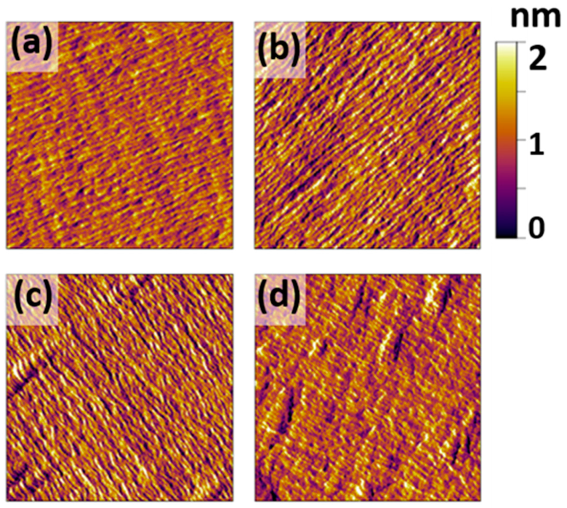
Because Mg was now used as surfactant during InGaN growth, the layers with H2 pulses may not be as necessary. Decreasing the cycle time during which H2 was introduced during growth or possibly eliminating the entire step would lead to an immediate increase in the effective In composition. For the set of experiments exploring this parameter, the growth temperature was set to 840 °C, and the total InGaN layer thickness was decreased to 100 nm to maintain coherent growth despite the expected increase in the In composition and lattice mismatch. Decreasing the time of the H2 pulses by one-third and two-thirds showed no emergence of hillocks, as shown in Figure 2a–c. However, when the H2 pulses were entirely eliminated, dense hexagonal hillocks emerged on the sample surface. The AFM images taken from the samples in this series showed that although there were no hexagonal surface hillocks present, elongated rhombus-shaped features appeared as the time the H2 pulses were decreased (Figure 2). Note that the surface steps are typical of N-polar films grown on miscut substrates [41]. As expected, the In composition increased with the decrease in the duration of the H2 pulse, and increased to 14.2% for the InGaN layer grown with only one-third of the original H2 insertion time (Figure 3) compared to 10.6% In for equal N2 and H2/N2 cycle times.
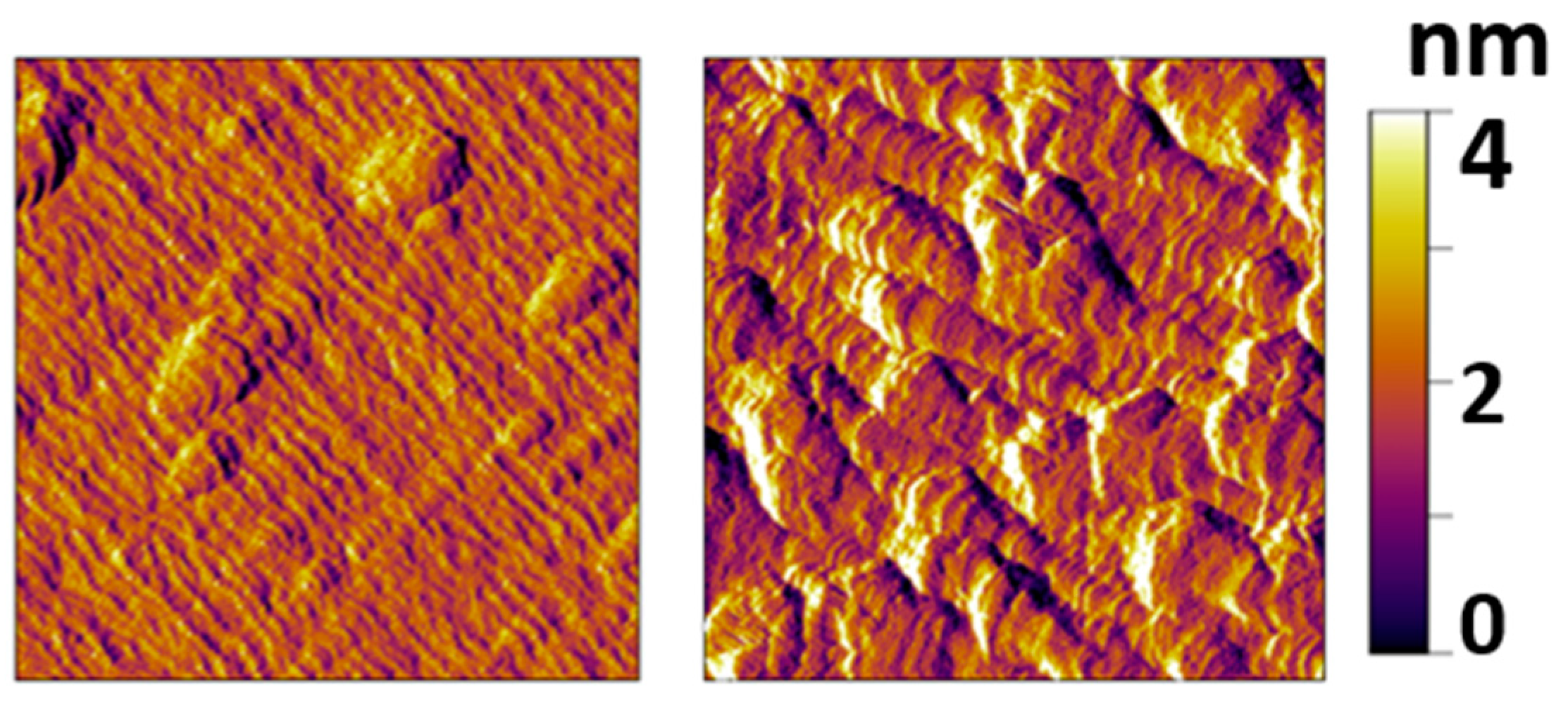
For the next experiments, a one-third reduced time of H2 pulse, corresponding to 2 nm InGaN/0.7 nm GaN in each loop, and a Cp2Mg flow of 36 nmol/min, were chosen. When the growth temperature was decreased from 840 to 820 °C, a very sparse coverage of hillocks was observed under low magnification (100 × 75 µm) in the optical microscope. The In composition for this InGaN layer was found to be 17.1%. Decreasing the growth temperature further to 800 °C caused the hillocks to reappear, but these were largely eliminated by increasing the Cp2Mg flow to 48 nmol/min. However, AFM images, presented in Figure 4, showed an increase in surface roughness due to the appearance of features similar to the elongated rhombus-shaped features measured for the sample depicted in Figure 2c Thus, the sample grown at 820 °C, using a Cp2Mg flow of 36 nmol/min and containing 17.1% In, was the sample with the highest composition exhibiting a hillock-free and smooth surface obtained in this study.
The morphology of the hillock-free sample grown at 800 °C, which contained 19.8% In, indicated that the layer may have started relaxing via roughening, a well-known relaxation mechanism [42]; indeed, its RSM showed a relaxation of 23%. Interestingly, the sample grown at 820 °C containing 17.1% In with a smooth surface also showed 15% relaxation, which was unexpected because there was no indication of any relaxation via roughening from AFM shown in Figure 4. The sparse rhombus-like features should not have caused the relaxation as they were similar to those seen in the layer grown at 840 °C, which contained 11.1% In (Figure 2c) and was fully strained. The mechanism leading to the relaxation in the smooth samples is currently unclear and requires further study.
Figure 5 summarizes the results obtained for all samples in this study, plotting the presence or absence of hillocks as a function of growth temperature and Cp2Mg flow. The graph illustrates the inverse relationship between Cp2Mg flow and growth temperature at the onset of hillock formation. The onset was defined for surfaces which exhibited hillocks under 20× magnification in the optical microscope, but no hillocks under 50× magnification. The samples at this onset are still termed hillock-free because they are suitable for device fabrication.
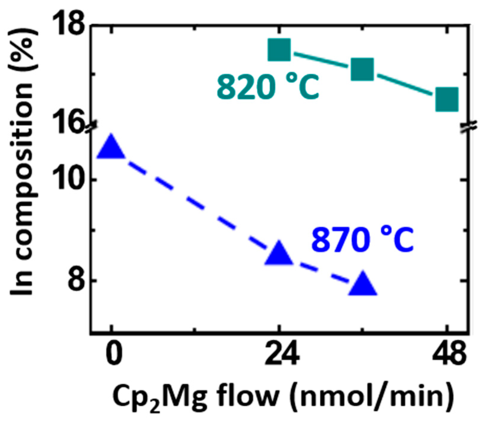
Figure 6 illustrates the impact of the Cp2Mg addition on the In composition of the digital InGaN layers. Heavy Mg doping to the order of 1021 cm−3 was previously reported to cause a decrease in In incorporation in Ga-polar InGaN films [43]. Although our Mg doping was ~9×1019 cm−3 (determined from GaN:Mg SIMS calibration samples), it nonetheless adversely affected the In incorporation. For both samples grown at 870 and 820 °C, the In composition decreased with increasing the Mg precursor injection (Figure 6). Nevertheless, because the presence of Mg enabled the deposition of smooth InGaN films at lower temperatures, a higher In composition in the digital InGaN films could be achieved.

4. Conclusions

In conclusion, InGaN layers with In composition of 17.1% and good surface morphology were demonstrated using a digital growth method using both H2 and Cp2Mg as surfactants. Although the presence of Mg adversely affected the In incorporation, the Mg addition enabled hillock-free growth at lower temperatures and growth of InGaN layers with an overall higher In content.

Author Contributions

Conceptualization, N.H., A.K., S.S.P. and S.K.; methodology, N.H. and S.K.; software, N.H.; validation, N.H. and S.K.; formal analysis, N.H. and S.K.; investigation, N.H., A.K. and S.S.P.; resources, S.K. and U.K.M.; data curation, N.H. and A.K.; writing—original draft preparation, N.H. and S.K.; writing—review and editing, N.H., S.K. and U.K.M.; visualization, N.H.; supervision, S.K. and U.K.M.; project administration, S.K. and U.K.M.; funding acquisition, U.K.M. All authors have read and agreed to the published version of the manuscript.

Funding

This work was supported in part by the ONR (Paul Maki) and the Semiconductor Research Corporation (SRC) and DARPA under the ComSenTer JUMP program.

Conflicts of Interest

The authors declare no conflict of interest.

References

  1. Langer, T.; Kruse, A.; Ketzer, F.A.; Schwiegel, A.; Hoffmann, L.; Jönen, H.; Bremers, H.; Rossow, U.; Hangleiter, A. Origin of the “green gap”: Increasing nonradiative recombination in indium-rich GaInN/GaN quantum well structures. Phys. Status Solidi C 2011, 8, 2170–2172. [Google Scholar] [CrossRef]
  2. Nakamura, S.; Senoh, M.; Iwasa, N.; Nagahama, S. Superbright Green InGaN Single-Quantum-Well-Structure Light-Emitting Diodes. Jpn. J. Appl. Phys. 1995, 34, L1332. [Google Scholar] [CrossRef]
  3. Chichibu, S.; Azuhata, T.; Sota, T.; Nakamura, S. Spontaneous emission of localized excitons in InGaN single and multiquantum well structures. Appl. Phys. Lett. 1996, 69, 4188–4190. [Google Scholar] [CrossRef]
  4. Narukawa, Y.; Kawakami, Y.; Funato, M.; Fujita, S.; Fujita, S.; Nakamura, S. Role of self-formed InGaN quantum dots for Role of self-formed InGaN quantum dots for emitting at 420 nm. Appl. Phys. Lett. 1997, 70, 981. [Google Scholar] [CrossRef]
  5. Mukai, T.; Narimatsu, H.; Nakamura, S. Amber InGaN-Based Light-Emitting Diodes Operable at High Ambient Temperatures. Jpn. J. Appl. Phys. 1998, 37, L479. [Google Scholar] [CrossRef]
  6. Gupta, C.; Tsukada, Y.; Romanczyk, B.; Pasayat, S.S.; James, D.-A.; Ahmadi, E.; Keller, S.; Mishra, U.K. First demonstration of improvement in hole conductivity in c-plane III-Nitrides through application of uniaxial strain. Jpn. J. Appl. Phys. 2019, 58, 030908. [Google Scholar] [CrossRef]
  7. Li, W.; Pasayat, S.; Guidry, M.; Romanczyk, B.; Zheng, X.; Gupta, C.; Hatui, N.; Keller, S.; Mishra, U.K. First experimental demonstration and analysis of electrical transport characteristics of a GaN-based HEMT with a relaxed InGaN channel. Semicond. Sci. Technol. 2020, 35, 075007. [Google Scholar] [CrossRef]
  8. Dreyer, C.E.; Janotti, A.; van de Walle, C.G. Effects of strain on the electron effective mass in GaN and AlN. Appl. Phys. Lett. 2013, 102, 142105. [Google Scholar] [CrossRef] [Green Version]
  9. Nakamura, S.; Senoh, M.; Iwasa, N.; Nagahama, S. High-Brightness InGaN Blue, Green and Yellow Light-Emitting Diodes with Quantum Well Structures. Jpn. J. Appl. Phys. 1995, 34, L797. [Google Scholar] [CrossRef]
  10. Matthews, J.W.; Blakeslee, A.E. Defects in epitaxial multilayers. J. Cryst. Growth 1974, 27, 118. [Google Scholar] [CrossRef]
  11. Matsuoka, T.; Yoshimoto, N.; Sasaki, T.; Katsui, A. Wide-Gap Semiconductor InGaN and InGaAln Grown by MOVPE. Available online: https://dl.acm.org/doi/10.1007/BF02655831 (accessed on 1 May 2021).
  12. Keller, S.; Mishra, U.K.; DenBaars, S.P. Flow Modulation Epitaxy of Indium Gallium Nitride. J. Electron. Mater. 1997, 26, 10. [Google Scholar] [CrossRef]
  13. Reed, M.J.; El-Masry, N.A.; Parker, C.A.; Roberts, J.C.; Bedair, S.M. Critical layer thickness determination of GaN/InGaN/GaN double heterostructures. Appl. Phys. Lett. 2000, 77, 4121. [Google Scholar] [CrossRef]
  14. Holec, D.; Costa, P.M.F.J.; Kappers, M.J.; Humphreys, C.J. Critical thickness calculations for InGaN/GaN. J. Cryst. Growth 2007, 303, 314. [Google Scholar] [CrossRef]
  15. Leyer, M.; Stellmach, J.; Meissner, C.; Pristovsek, M.; Kneissl, M. The critical thickness of InGaN on (0 0 01)GaN. J. Cryst. Growth 2008, 310, 4913. [Google Scholar] [CrossRef]
  16. Matsuoka, T.; Sasaki, T.; Katsui, A. Growth and properties of a wide-gap semiconductor InGaN. Optoelectronics Devices and Technol. 1990, 5, 53. [Google Scholar]
  17. Keller, S.; Keller, B.P.; Kapolnek, D.; Abare, A.C.; Masui, H.; Coldren, L.A.; Mishra, U.K.; DenBaars, S.P. Growth and characterization of bulk InGaN films and quantum wells. Appl. Phys. Lett. 1996, 68, 3147. [Google Scholar] [CrossRef]
  18. Shimizu, M.; Kawaguchi, Y.; Hiramatsu, K.; Sawaki, N. MOVPE growth of thick homogeneous InGaN directly on sapphire substrate using AlN buffer layer. Solid-State Electron. 1997, 41, 145. [Google Scholar] [CrossRef]
  19. Singh, R.; Doppalapudi, D.; Moustakas, T.D.; Romano, L.T. Phase separation in InGaN thick films and formation of InGaN/GaN double heterostructures in the entire alloy composition. Appl. Phys. Lett. 1997, 70, 1089. [Google Scholar] [CrossRef]
  20. Yang, L.-H.; Zhang, B.-H.; Guo, F.-Q. Characteristics of an Indium-Rich InGaN p—n Junction Grown on a Strain-Relaxed InGaN Buffer Layer. Chin. Phys. Lett. 2013, 30, 047301. [Google Scholar] [CrossRef]
  21. Choi, J.-H.; Shojiki, K.; Tanikawa, T.; Hanada, T.; Katayama, R.; Matsuoka, T. Investigation of indium incorporation into InGaN by nitridation of sapphire substrate in MOVPE. Phys. Status Solidi C 2013, 10, 417. [Google Scholar] [CrossRef]
  22. Wu, X.H.; Elsass, C.R.; Abare, A.; Mack, M.; Keller, S.; Petroff, P.M.; DenBaars, S.P.; Speck, J.S. Structural origin of V-defects and correlation with localized excitonic centers in InGaN/GaN multiple quantum wells. Appl. Phys. Lett. 1998, 72, 692. [Google Scholar] [CrossRef]
  23. Cho, H.K.; Lee, J.Y.; Yang, G.M.; Kim, C.S. Formation mechanism of V defects in the InGaN/GaN multiple quantum wells grown on GaN layers with low threading dislocation density. Appl. Phys. Lett. 2001, 79, 215. [Google Scholar] [CrossRef]
  24. Wang, H.; Jiang, D.S.; Jahn, U.; Zhu, J.J.; Zhao, D.G.; Liu, Z.S.; Zhang, S.M.; Qiu, Y.X.; Yang, H. Investigation on the strain relaxation of InGaN layer and its effects on the InGaN structural and optical properties. Physica B 2010, 405, 4668–4672. [Google Scholar] [CrossRef]
  25. Zal Balushi, Y.; Redwing, J.M. The effect of polarity on MOCVD growth of thick. Appl. Phys. Lett. 2017, 110, 022101. [Google Scholar] [CrossRef] [Green Version]
  26. Keller, S.; Li, H.; Laurent, M.; Hu, Y.; Pfaff, N.; Lu, J.; Brown, D.F.; Fichtenbaum, N.A.; Speck, J.S.; DenBaars, S.P.; et al. Recent progress in metal-organic chemical vapor deposition of (000 1 ¯ )N-polar group-III nitrides. Semicond. Sci. Technol. 2014, 29, 113001. [Google Scholar] [CrossRef]
  27. Northrup, J.E.; Neugebauer, J. Indium-induced changes in Ga(0001) surface morphology. Phys. Rev. B 1999, 60, R8473(R). [Google Scholar] [CrossRef] [Green Version]
  28. Keller, S.; Fichtenbaum, N.A.; Furukawa, M.; Speck, J.S.; DenBaars, S.P.; Mishra, U.K. Growth and characterization of N-polar InGaN/GaN multiquantum wells. Appl. Phys. Lett. 2007, 90, 191908. [Google Scholar] [CrossRef]
  29. Shojiki, K.; Tanikawa, T.; Choi, J.-H.; Kuboya, S.; Hanada, T.; Katayama, R.; Matsuoka, T. Red to blue wavelength emission of N-polar (000 1 ¯ ) InGaN light-emitting diodes grown by metalorganic vapor phase epitaxy. Appl. Phys. Express 2015, 8, 061005. [Google Scholar] [CrossRef]
  30. Hatui, N.; Krishna, A.; Li, H.; Gupta, C.; Romanczyk, B.; Acker-James, D.; Ahmadi, E.; Keller, S.; Mishra, U.K. Ultra-high silicon doped N-polar GaN contact layers grown by metal-organic chemical vapor deposition. Semicond. Sci. Technol. 2020, 35, 095002. [Google Scholar] [CrossRef]
  31. Lund, C.; Hestroffer, K.; Hatui, N.; Nakamura, S.; DenBaars, S.P.; Mishra, U.K.; Keller, S. Digital growth of thick N-polar InGaN films on relaxed InGaN pseudosubstrates. Appl. Phys. Express 2017, 10, 111001. [Google Scholar] [CrossRef]
  32. Piner, E.L.; Behbehani, M.K.; El-Masry, N.A.; McIntosh, F.G.; Roberts, J.C.; Boutros, K.S.; Bedair, S.M. Effect of hydrogen on the indium incorporation in InGaN epitaxial films. Appl. Phys. Lett. 1997, 70, 461. [Google Scholar] [CrossRef]
  33. Pasayat, S.S.; Lund, C.; Tsukada, Y.; Catalano, M.; Wang, L.; Kim, M.J.; Nakamura, S.; Keller, S.; Mishra, U.K. Optimization of Digital Growth of Thick N-Polar InGaN by MOCVD. J. Electron. Mater. 2020, 49, 3450–3454. [Google Scholar] [CrossRef]
  34. Beaumont, B.; Haffouz, S.; Gibart, P. Magnesium induced changes in the selective growth of GaN by metalorganic vapor phase epitaxy. Appl. Phys. Lett. 1998, 72, 921. [Google Scholar] [CrossRef]
  35. Cheng, T.S.; Novikov, S.V.; Foxon, C.T.; Orton, J.W. Mechanisms of magnesium incorporation into GaN layers grown by molecular beam epitaxy. Solid State Commun. 1999, 109, 439. [Google Scholar] [CrossRef]
  36. Xing, H.; Green, D.S.; Yu, H.; Mates, T.; Kozodoy, P.; Keller, S.; DenBaars, S.P.; Mishra, U.K. Memory Effect and Redistribution of Mg into Sequentially Regrown GaN Layer by Metalorganic Chemical Vapor Deposition. Jpn. J. Appl. Phys. 2003, 42, 50. [Google Scholar] [CrossRef]
  37. Hashizume, T. Effects of Mg accumulation on chemical and electronic properties of Mg-doped p-type GaN surface. J. Appl. Phys. 2003, 94, 431. [Google Scholar] [CrossRef] [Green Version]
  38. Tanikawa, T.; Shojiki, K.; Aisaka, T.; Kimura, T.; Kuboya, S.; Hanada, T.; Katayama, R.; Matsuoka, T. Enhancement of surface migration by Mg doping in the metalorganic vapor phase epitaxy of N-polar (000 1 ¯ ) GaN/sapphire. Jpn. J. Appl. Phys. 2014, 53, 05FL05. [Google Scholar] [CrossRef]
  39. Zhang, L.; Tang, H.F.; Schieke, J.; Mavrikakis, M.; Kuech, T.F. The addition of Sb as a surfactant to GaN growth by metal organic vapor phase epitaxy. J. Appl. Phys. 2002, 92, 2304. [Google Scholar] [CrossRef] [Green Version]
  40. Junsong, C.; Xin, L.; Lubing, Z.; Shuang, Q.; Wei, G. Influence of initial growth conditions and Mg-surfactant on the quality of GaN film grown by MOVPE. J. Semicond. 2015, 36, 023005. [Google Scholar]
  41. Keller, S.; Fichtenbaum, N.A.; Wu, F.; Brown, D.; Rosales, A.; DenBaars, S.P.; Speck, J.S.; Mishra, U.K. Influence of the substrate misorientation on the properties of N-polar GaN films grown by metal organic chemical vapor deposition. J. Appl. Phys. 2007, 102, 083546. [Google Scholar] [CrossRef]
  42. Snyder, C.W.; Orr, B.G.; Kessler, D.; Sander, L.M. Effect of Strain on Surface Morphology in Highly Strained InGaAs Films. Phys. Rev. Lett. 1991, 66, 3032. [Google Scholar] [CrossRef] [PubMed]
  43. Gherasoiu, I.; Yu, K.M.; Hawkridge, M.; Reichertz, L.A.; Walukiewicz, W. Mg induced compositional change in InGaN alloys. Semicond. Sci. Technol. 2019, 34, 025014. [Google Scholar] [CrossRef]
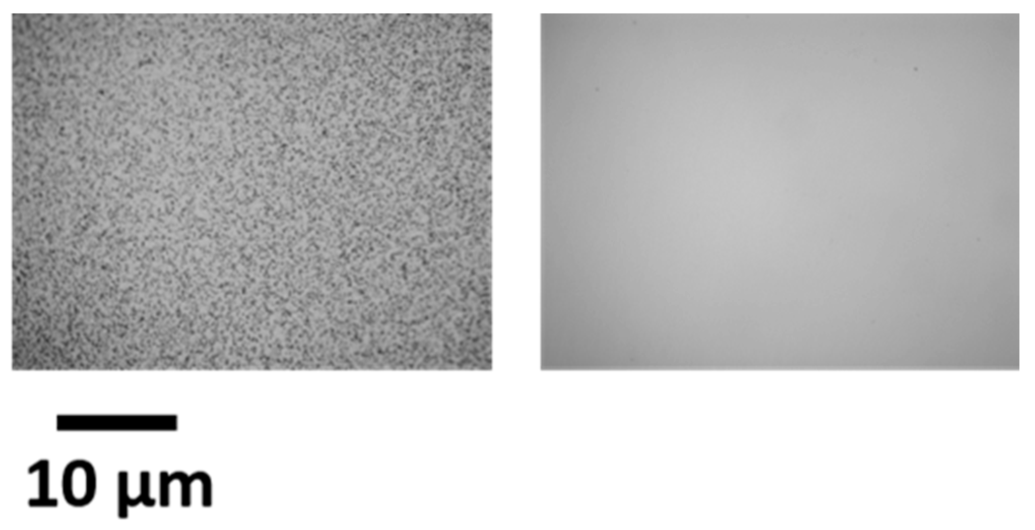
Figure 1. Optical microscopy images for samples grown at 850 °C (left) without Cp2Mg, and (right) with 48 nmol/min of Cp2Mg flow.
Electronics 10 01182 g001
Figure 2. AFM amplitude images of 5 × 5 µm for InGaN grown with various superlattice (SL) compositions with a Cp2Mg flow of 36 nmol/min: (a) 2 nm InGaN/2 nm GaN (In = 11.1%), (b) 2 nm InGaN/1.4 nm GaN (In = 12.6%), (c) 2 nm InGaN/0.7 nm GaN (14.2%), (d) all InGaN, no SL (21.1%). Note that image (d) was taken in the area between the hexagonal surface hillocks.
Electronics 10 01182 g002
Figure 3. Effective In composition (measured by XRD) with decreasing hydrogen pulse time (resulting in decreasing GaN thickness in the SL). The samples were gown at 840 °C with a Cp2Mg flow of 36 nmol/min. The surface morphology can be seen in Figure 2 with GaN/InGaN ratios of 1, 0.67, 0.33, and 0, corresponding to (ad), respectively.
Electronics 10 01182 g003
Figure 4. AFM amplitude images of 5 × 5 µm of InGaN grown at 820 °C (left) (In = 16.5%) and 800 °C (right) (In = 19.8%). The samples were grown with a Cp2Mg flow of 48 nmol/min.
Electronics 10 01182 g004
Figure 5. Chart of the presence of hillocks with varying temperature and Mg precursor flow. “Hillocks” are defined as samples showing hillocks under 50× magnification (40 × 30 µm). The empty symbols correspond to 200 nm thick layers, with 2 nm InGaN/2 nm GaN SLs, whereas filled symbols represent 100 nm thick layers with 2 nm InGaN/0.7 nm GaN SLs. The shaded region shows the growth parameter range in which hillocks will appear, and the hypotenuse marks the samples which are hillock-free under 50× magnification, but show some hillocks under 20× magnification.
Electronics 10 01182 g005
Figure 6. In composition as a function of Mg precursor flow at two different growth temperatures.
Electronics 10 01182 g006
Publisher’s Note: MDPI stays neutral with regard to jurisdictional claims in published maps and institutional affiliations.