Abstract
Flexible electronics is a field gathering a growing interest among researchers and companies with widely varying applications, such as organic light emitting diodes, transistors as well as many different sensors. If the circuit should be portable or off-grid, the power sources available are batteries, supercapacitors or some type of power generator. Thermoelectric generators produce electrical energy by the diffusion of charge carriers in response to heat flux caused by a temperature gradient between junctions of dissimilar materials. As wearables, flexible electronics and intelligent packaging applications increase, there is a need for low-cost, recyclable and printable power sources. For such applications, printed thermoelectric generators (TEGs) are an interesting power source, which can also be combined with printable energy storage, such as supercapacitors. Poly(3,4-ethylenedioxythiophene)-poly(styrenesulfonate), or PEDOT:PSS, is a conductive polymer that has gathered interest as a thermoelectric material. Plastic substrates are commonly used for printed electronics, but an interesting and emerging alternative is to use paper. In this article, a printed thermoelectric generator consisting of PEDOT:PSS and silver inks was printed on two common types of paper substrates, which could be used to power electronic circuits on paper.
1. Introduction
Flexible electronics is a field gathering a growing interest among researchers and companies. The applications vary widely, as the term flexible and printed electronics encompass everything from Organic Light Emitting Diodes (OLEDs) and transistors, as well as a multitude of different sensors, and also the fabrication of conductive tracks on non-standard substrates [1,2,3,4,5,6,7,8,9,10,11]. One interesting application field is electrical circuits covering large areas, i.e., where components, such as sensors, are placed over an area that would not be practical using standard printed circuit boards (PCBs) or flexible PCBs. This could be circuits on posters and cardboard boxes, and as wearables or sensors covering large areas, etc. [9,10,11]. Also, micro LEDs are an interesting device that could be powered using a low power source [12,13,14].
If the circuit should be portable or off-grid, the power sources available are batteries, supercapacitors or some type of power generator [15,16,17]. To add batteries is not always possible, or limits the usefulness, shelf life or operating lifetime of the device.
There are several options to manufacture power generators on flexible substrates, including triboelectric and thermoelectric generators [18,19,20,21,22]. Thermoelectric generators (TEGs) produce electrical energy by the diffusion of charge carriers in response to heat flux caused by a temperature gradient between junctions of dissimilar materials [18]. The Seebeck coefficient, S, relates the magnitude of charge carrier flow to the temperature gradient.
Thermoelectric materials are commonly compared using a dimensionless figure of merit, denoted ZT, that depends on the Seebeck coefficient and the electrical and thermal conductivity of the material. There are many types of thermoelectric materials, where Bi2Te3 and Bi2Se3 are among the ones with the highest figure of merits in the range of approximately 1.0 ZT, compared to 0.25 ZT reported for optimized poly(3,4-ethylenedioxythiophene)-poly(styrenesulfonate) (PEDOT:PSS) [23,24]. The reason that not exclusively high-performance materials are used for TEGs is due to a combination of cost, processability and applications.
As the use of wearables, flexible electronics and intelligent packaging applications increases, there is a need for low-cost, recyclable and printable power sources. For such applications, printed TEGs are an interesting power source, which can also be combined with a printable energy storage device such as supercapacitors [15,17].
PEDOT:PSS is a conductive polymer that has been widely used for transistors, sensors and has also gathered interest as a thermoelectric material [25,26,27,28].
Substrates used for printed electronics are commonly plastic, as they have a low surface roughness, temperature tolerance, dimensional stability and barrier properties against oxygen and water.
An interesting and emerging alternative is to use paper as a substrate, which has the benefits of being environmentally friendly, recyclable and renewable. Also, there is an interest to include printed electronic functions together with existing paper products such as packaging [4,5,6,8,9,10,11].
The manufacturing and material cost of the presented printed TEGs on paper can be kept low if screen printing, stencil printing, or roll-to-roll production techniques is used. The technological threshold to start such production can also be considered low, as both PEDOT:PSS and silver (Ag) ink formulated for screen printing are readily available and the printing equipment is the same as used for graphical printing.
Such printed TEGs can be also of interest where large areas could be covered with TEGs, but where the high-cost of traditional TEGs are prohibiting, and therefore, are not utilized. This could be on wastewater pipes, on buildings and similar places. In such cases, a low performance can be justified if the cost is significantly lower.
In this article, we present a TEG consisting of PEDOT:PSS and silver (Ag) inks, which can be used to power electronic circuits on paper. The aim of the work is to study the effect that different paper substrates can have on the performance of PEDOT:PSS-based thermoelectric generators, compared to plastic substrates.
The substrates used are photo paper (PP), cardboard (CB) and polyetentereftalat (PET). The PP is a high-quality paper with a very low surface roughness and with a thick (approximately 50 µm), highly absorptive coating, consisting of AlO(OH), intended for rapid solvent absorption from ink-jet inks.
2. Materials and Methods
The TEG were designed as alternating lines, consisting of PEDOT:PSS and Ag, with a slight overlap to obtain a good electrical connection, as shown in Figure 1. The printing was performed manually using a 100 µm thick steel stencil with the pattern and a metal squeegee, with dimensions shown in Figure 1.
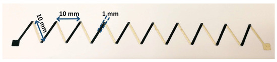
Figure 1.
Printed thermoelectric generators (TEG) pattern showing the alternating Ag and poly(3,4-ethylenedioxythiophene)-poly(styrenesulfonate) (PEDOT:PSS) elements.
The inks used for the preparation of the TEGs were PEDOT:PSS screen ink, 5 wt.% Orgacon EL-P-501 (768650, Sigma Aldrich), with a viscosity stated to be between 30 to 90 × 103 mPas, and screen print Ag ink (Loctite EDAG 725A, Henkel). The TEGs were printed on Canon PT-101 photo paper, Invercote-T cardboard (Iggesund, Sweden) and on PET (100 µm). Firstly, the Ag layers were printed and dried in an oven at 110 ℃ for 20 min. Then, the process was repeated with PEDOT:PSS ink and the same drying conditions.
As a comparison, carbon screen ink (Henkel) and Ag screen ink were used to print the same TEG structure on PP.
The thickness of deposited lines was measured using a Bruker Dektak XT stylus profilometer with a diamond tip and a stylus force of 0.03 mg. For data analysis, Vision64 (Bruker) Operation and Analysis Software were used. The surfaces of the PEDOT:PSS lines were scanned using atomic force microscopy (AFM), where a Dimension ICON (Bruker) working in PeakForce mode with ScanAsyst-Air probe was used under ambient conditions.
Thermoelectric measurements were performed using a Peltier cooler with a PT-100 temperature sensor to monitor the temperature of the cold side. Voltages were measured using an Agilent 34405A multimeter. Currents were measured through a load resistor matching the resistance of the thermoelectric element using a Keithley 2611A source meter. Spring-loaded probes were used, where the positive probes were positioned on the PEDOT:PSS electrode and the negative probes on the Ag electrode. The TEGs were positioned with one row of junctions on the cooler and the other row on the insulating foam, as shown in Figure 2. The hot side of the sample was kept in room temperature, while the cool side was cooled down to different temperatures.
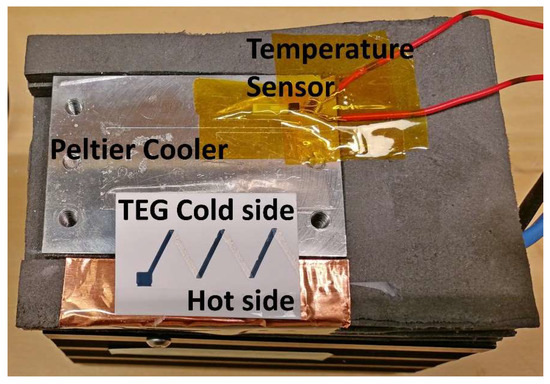
Figure 2.
Thermoelectric measurement setup consisting of a Peltier cooler element and a PT-100 temperature sensor as indicated in the figure. A printed TEG consisting of alternating PEDOT:PSS and Ag lines is positioned halfway over the Peltier element (cold side) and room temperature (hot side).
Additional temperature measurements on the hot and cold side of the TEG were performed using a thermal imaging camera (FLIR i7) as shown in Figure 3. The temperature on the hot side (room temperature) was seen to also decrease, as the thermoelectric cooler will have an effect on the nearby surroundings.
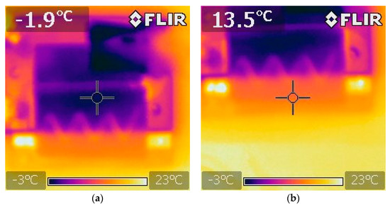
Figure 3.
Thermal imaging camera showing the cold (a) and hot side (b) of the TEG mounted on the thermoelectric measurement setup.
3. Results
The Seebeck coefficients and power factors were calculated using voltages and currents measured at a temperature difference of 15 K. The Seebeck coefficient is defined as the voltage output change per degree Kelvin, as shown in Equation (1).
The power factor is a figure of merit defined as shown in Equation (2).
where W is the power calculated from the measured current and voltage, L is the length of one thermoelectric element (10 mm), A is the cross-section area of the PEDOT:PSS line as measured by profilometry and ΔT is the temperature difference.
The results of the PEDOT:PSS TEGs fabricated on the different substrates as well as for the carbon/Ag TEG is summarized in Table 1, where the resistance is a mean value obtained by measuring along each printed line. The Seebeck value for Ag is deducted from the values presented in Table 1, using the absolute value of +1.5 µV/K (not relative Pt) [29].

Table 1.
Measured parameters of the printed PEDOT:PSS/Ag TEGs on Photo Paper (PP), Cardboard (CB) and polyetentereftalat (PET) substrates as well the graphite/Silver (Ag) reference sample.
Additional measurements were carried out on the CB TEG to determine the voltage and currents at increasing temperature differences, as shown in Figure 4. Due to difficulties in adjusting the Peltier element to exact temperatures, the measurements were carried out at somewhat irregular temperature steps.
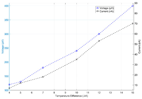
Figure 4.
Voltages and currents measured on TEGs printed on cardboard (CB) at temperature differences from 4–15 K.
It can be seen that the voltage and current increased linearly, and a linear fit determined that the voltage change was 25 µV/K and the current change was 5 nA/K.
Additionally, power factors were obtained for different temperatures, as measured on the cold side of the setup. The results is displayed in Figure 5, where some irregularities were observed at colder temperatures, but the trend was that the power factor increases for lower temperatures.
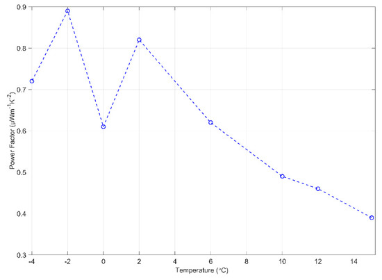
Figure 5.
Power factors for TEGs printed on CB, calculated at different temperatures on the cold side of the measurement setup, as indicated on the x-axis.
The print quality of the TEGs printed on PP, CB and PET is shown in Figure 6, where it was visible that the Ag lines on the PET, flowed out the most, otherwise the line definition was sharp.
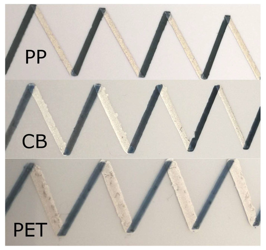
Figure 6.
Difference in linewidths and print quality of PEDOT:PSS lines and Ag lines on plain paper (PP), CB and polyetentereftalat (PET) substrates.
The optical profilometry measurements show that the PEDOT:PSS lines had a consistent width on the different substrates that was close to the width of the stencil, 1 mm, as can be seen in Figure 7. The thickness could be seen to differ more, where the thickness on the PET substrate was approximately 2 µm, while on the PP it was approximately 3 µm. The thickness on the CB showed the largest variations, with valleys and peaks ranging from 1 to 4 µm. The cross-section of the lines used for the power factor calculations was obtained by integration of the areas below the plotted lines, in Figure 7. The cross-section values obtained are; CB = 2.7 × 10⁻⁹ m2, PP = 2.9 × 10⁻⁹ m2, PET = 1.9 × 10⁻⁹ m2. For the carbon/Ag TEG, an estimated area of 2.5 × 10⁻⁹ m2 was used.
Figure 7.
Optical profilometry of the PEDOT:PSS lines on the CB, PP and PET substrates showing small variations in width.
The profilometry analysis of the Ag ink lines, shown in Figure 8, revealed that the lines printed on CB and PP were close to the width of the stencil, but the line on the PET had flowed out to a width of 1.4 mm.
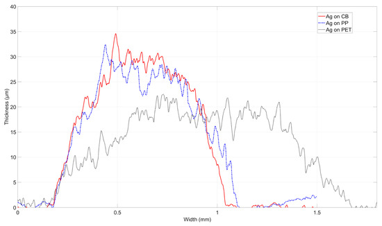
Figure 8.
Optical profilometry of the Ag lines on the CB, PP and PET substrates showing small variations in width.
The AFM characterization of the PEDOT:PSS is shown in Figure 9, with the substrates (CB, PP, PET) marked. The surfaces of the PEDOT:PSS were similar in appearance, although, on PET, the surface showed some smaller, round grains that were not visible on the other surfaces.
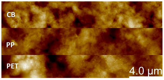
Figure 9.
AFM measurements showing the surface of the PEDOT:PSS on CB (top), PP (middle) and PET (bottom).
4. Discussion
The screen-printed TEGs on paper demonstrated here showed the Seebeck coefficients were in the range of 22 to 27 µV/K. These were on average, compared with untreated PEDOT:PSS (around 20 µV/K) [28], low compared to optimized PEDOT:PSS, which showed a Seebeck coefficient of 200 µV/K [27].
The power factors were found to be 0.8–1.3 µW m−1K−2, which was comparable to references that show values of 1.29 µW m−1K−2 for untreated PEDOT:PSS, although much lower than the reported 324 µW m−1K−2 for doped and optimized PEDOT:PSS [27,28]. However, the aim of the work presented here was to investigate a facile fabrication method of TEGs on different types of paper substrates, rather than to improve PEDOT:PSS as a thermoelectric material.
The reference TEG consisting of carbon/Ag printed on a PET substrate showed, as expected, the lower Seebeck coefficient value of only −11.5 µV/K and a power factor of 0.4 µW m−1K−2. This was expected of carbon material, which has a low Seebeck coefficient and demonstrates that the cooling and measurement setup produced reasonable results.
Considering the substrates used in this work, the PP was a substrate with very low surface roughness and a highly absorbent, thick top coating of approximately 50 µm. The coatings of PP are used for rapid absorption of solvent from ink-jet inks, and are therefore, highly porous. The CB substrate is used for packaging and is commonly found in boxes for retail products. The surface roughness of CB was higher than for PP, although still low compared to plain copy paper, and the surface was less absorbing. The PET substrate acted as a reference, as it has a low surface roughness and was non-porous.
The profilometry measurements on the PEDOT:PSS lines in Figure 7 showed that the ink did not flow out after printing, and considering that the viscosity was given by the manufacturer to be in the range between 30 to 90 Pa·s, this can be expected.
The thickness on the CB substrate showed the largest variations, with valleys and peaks ranging from 1 to 4 µm. This could be explained by the higher surface roughness of the CB substrate compared to the very low surface roughness of the PET and PP.
The profilometry analysis of the Ag ink lines in Figure 8 showed that the line on the PET did flow out to a width of 1.4 mm, a considerable difference to the stencil width of 1 mm. The lower viscosity of the Ag ink, 16.5 Pa·s, in combination with the non-porous surface of the PET substrate, could explain this behavior.
When examining the AFM measurements of the PEDOT:PSS surface on the different substrates, the feature that stood out was the small grains present on the larger grains, visible on the PET substrate (Figure 9). This feature did not seem to have a significant effect on the resistance, which was 390 Ω on PET and 380 Ω on PP, respectively.
PEDOT:PSS has been shown to be sensitive to many parameters, where chemical treatment is an effective way to modify the conductance and Seebeck coefficient. The conduction mechanism of PEDOT:PSS has been stated as the Mott’s variable range hopping (VRH) [30,31] between conductive PEDOT grains. It has been shown that the deposition method can have an effect on the resulting morphology of the PEDOT grains, where thin, spin-coated films, were shown to cause flattening of the spherical PEDOT particles due to solvent evaporation [31]. This resulted in a higher resistance caused by the increased number of PSS rich grain boundaries in the Z direction. In Reference [32], it was shown that thin ink-jet printed PEDOT:PSS films on photo paper showed two orders of magnitude higher resistance than when printed on cardboard, and three orders higher compared to glass. This difference was also speculated to be caused by the chemical content in the PP coating [32].
It is therefore interesting to note that, in this case of the stencil-printed thermoelectric generators, there was no large variation of the Seebeck coefficients when comparing the three substrates. The PEDOT:PPS printed on CB show a resistance of 760 Ω, compared to 380 Ω on PP and 390 Ω on PET, which was a small difference compared to the two and three orders of magnitude observed for the thin, ink-jet printed films in Reference [32]. One obvious difference was that the stencil-printed PEDOT:PSS films were several micrometers thick, while the ink-jet printed measures only tens of nanometers. The viscosity of the screen ink used here was also much higher, between 30 to 90 × 103 mPa·s, compared to 7–12 mPa·s for the ink-jet ink. This led to less sensitivity to substrate variations, as a several micrometer thick layer will fill in much larger irregularities of the substrates. There also seemed to be no discernable effect of the different chemical content in the PP, CB and PET substrates on the resistance or Seebeck coefficients, which was the case for the ink-jet printed films. This could likely be attributed to the fact that much less solvent of the high viscosity ink penetrates the coating layers of the paper substrates, and therefore, there was less transport of chemical content from the coating layers.
5. Conclusions
It was found that it was possible to use stencil printing to fabricate PEDOT:PSS TEGs on different, commercial, paper substrates with no difference in Seebeck coefficients, compared to PET plastic substrates. In the case of PP, the resistance was similar, even slightly lower, than on PET. Stencil-printed thermoelectric generators using high viscous PEDOT:PSS ink on paper substrates show no less performance than when printed on plastic PET substrates. Of course, to obtain a higher performance TEG device, the PEDOT:PSS material needs to be optimized, as has previously been shown [23,24]. However, it has been shown that printing is a possible route to fabricate TEG power sources. The applications can be for wearables and packaging, as well as low-cost TEGs for large areas.
Author Contributions
Conceptualization, H.A., G.T. and H.O.; Methodology, H.A. and G.T.; Data curation, H.A., P.S. and J.M.; Investigation, H.A., P.S., J.M.; Visualization, H.A. and J.M.; Project administration, H.A., G.T. and H.O.; Validation, H.A.; Writing—original draft preparation, H.A.; Writing—review and editing, H.A., P.S., G.T., M.E., R.Z., J.M. and H.O.; Funding acquisition, H.O.
Funding
This research was funded by the Swedish Knowledge Foundation (KKS).
Conflicts of Interest
The authors declare no conflict of interest.
References
- Rivnay, J.; Inal, S.; Salleo, A.; Owens, R.M.; Berggren, M.; Malliaras, G.G. Organic electrochemical transistors. Nat. Mater. 2011, 10, 429–433. [Google Scholar] [CrossRef]
- Berggren, M.; Nilsson, D.; Robinson, N.D. Organic materials for printed electronics. Nat. Mater. 2007, 6, 3–5. [Google Scholar] [CrossRef] [PubMed]
- Subramanian, V.; Chang, P.C.; Lee, J.B.; Molesa, S.E.; Volkman, S.K. Printed organic transistors for ultra low cost RFID applications. IEEE Trans. Compon. Packag. Technol. 2005, 28, 742–747. [Google Scholar] [CrossRef]
- Tobjörk, D.; Österbacka, R. Paper electronics. Adv. Mater. 2011, 23, 1935–1961. [Google Scholar] [CrossRef]
- Öhlund, T.; Örtegren, J.; Forsberg, S.; Nilsson, H.-E. Paper surfaces for metal nanoparticle inkjet printing. Appl. Surf. Sci. 2012, 259, 731–739. [Google Scholar] [CrossRef]
- Andersson, H.; Manuilskiy, A.; Unander, T.; Lidenmark, C.; Forsberg, S.; Nilsson, H.-E. Inkjet printed silver nanoparticle humidity sensor with memory effect on paper. IEEE Sensors J. 2012, 12, 1901–1905. [Google Scholar] [CrossRef]
- Sandström, A.; Dam, H.F.; Krebs, F.C.; Edman, L. Ambient fabrication of flexible and large-area organic light-emitting devices using slot-die coating. Nat. Commun. 2012, 3, 1002. [Google Scholar] [CrossRef]
- Andersson, H.; Manuilskiy, A.; Lidenmark, C.; Gao, J.; Öhlund, T.; Forsberg, S.; Örtegren, J.; Schmidt, W.; Nilsson, H.-E. The influence of paper coating content on room temperature sintering of silver nanoparticle ink. Nanotechnology 2013, 24, 455203. [Google Scholar] [CrossRef] [PubMed]
- Siegel, A.C.; Phillips, S.T.; Dickey, M.D.; Lu, N.; Suo, Z.; Whitesides, G.M. Foldable Printed Circuit Boards on Paper Substrates. Adv. Funct. Mater. 2010, 20, 28–35. [Google Scholar] [CrossRef]
- Li, X.; Andersson, H.A.; Sidén, J.; Schön, T. Soldering surface mount components on screen printed Ag patterns on paper and Polyimide substrates for hybrid printed electronics. Flex. Printed Elec. 2018, 3, 1. [Google Scholar] [CrossRef]
- Andersson, H.A.; Manuilskiy, A.; Haller, S.; Hummelgård, M.; Sidén, J.; Hummelgård, C.; Olin, H.; Nilsson, H.-E. Assembling surface mounted components on ink-jet printed double sided paper circuit board. Nanotechnology 2014, 25, 9. [Google Scholar] [CrossRef]
- Lee, H.E.; Choi, J.; Lee, S.H.; Jeong, M.; Shin, J.H.; Joe, D.J.; Kim, D.; Kim, C.W.; Park, J.H.; Lee, J.H.; et al. Monolithic Flexible Vertical GaN Light-Emitting Diodes for a Transparent Wireless Brain Optical Stimulator. Adv. Mater. 2018, 30, 1800649. [Google Scholar] [CrossRef] [PubMed]
- Lee, S.H.; Kim, J.; Shin, J.H.; Lee, H.E.; Kang, I.-S.; Gwak, K.; Kim, D.-S.; Kim, D.; Lee, K.J. Optogenetic control of body movements via flexible vertical light-emitting diodes on brain surface. Nano Energy 2018, 44, 447–455. [Google Scholar] [CrossRef]
- Lee, H.E.; Park, J.H.; Kim, T.J.; Im, D.; Shin, J.H.; Kim, D.H.; Mohammad, B.; Kang, I.-S.; Lee, K.J. Novel Electronics for Flexible and Neuromorphic Computing. Adv. Funct. Mater. 2018, 28, 1801690. [Google Scholar] [CrossRef]
- Ervin, M.H.; Le, L.T.; Lee, W.Y. Inkjet-Printed Flexible Graphene-Based Supercapacitor. Electrochim. Acta 2014, 147, 610–616. [Google Scholar] [CrossRef]
- Wang, Y.; Lai, W.; Jiang, Z.; Yang, C. All-printed paper based surface mountable super capacitors. IEEE Trans. Dielectr. Electr. Insul. 2017, 24, 2676–2681. [Google Scholar]
- Blomquist, N.; Wells, T.; Andres, B.; Bäckström, J.; Forsberg, S.; Olin, H. Metal-free supercapacitor with aqueous electrolyte and low-cost carbon materials. Sci. Rep. 2017, 7, 39836. [Google Scholar] [CrossRef] [PubMed]
- Wang, Z.; Lin, L.; Chen, J.; Niu, S.; Zi, Y. Triboelectric Nanogenerators; Springer: Heidelberg, Germany, 2016. [Google Scholar]
- Zhang, R.; Hummelgård, M.; Olsen, M.; Örtegren, J.; Olin, H. Nanogenerator made of ZnO nanosheet networks. Semicond. Sci. Technol. 2017, 32, 5. [Google Scholar] [CrossRef]
- Zhang, R.; Örtegren, J.; Hummelgård, M.; Olsen, M.; Andersson, H.; Olin, H. Harvesting triboelectricity from the human body using non-electrode triboelectric nanogenerators. Nano Energy 2017, 45, 298–303. [Google Scholar] [CrossRef]
- Siddique, A.R.M.; Mahmud, S.; van Heyst, B. A review of the state of the science on wearable thermoelectric power generators (TEGs) and their existing challenges. Renew. Sust. Energ. Rev. 2017, 73, 730–744. [Google Scholar] [CrossRef]
- Suemori, K.; Hoshino, S.; Kamata, T. Flexible and lightweight thermoelectric generators composed of carbon nanotube–polystyrene composites printed on film substrate. Appl. Phys. Lett. 2013, 103, 153902. [Google Scholar] [CrossRef]
- Goldsmid, H.J. Bismuth Telluride and Its Alloys as Materials for Thermoelectric Generation. Materials 2014, 7, 2577–2592. [Google Scholar] [CrossRef]
- Madan, D.; Chen, A.; Wright, P.K.; Evans, J.W. Printed Se-Doped MA n-Type Bi2Te3 Thick-Film Thermoelectric Generators. J. Electron. Mater. 2012, 41, 1481–1486. [Google Scholar] [CrossRef]
- Cowen, L.M.; Atoyo, J.; Carnie, M.J.; Baran, D.; Schroeder, B.C. Review—Organic Materials for Thermoelectric Energy Generation. ECS J. Solid State Sci. Technol. 2017, 6, N3080–N3088. [Google Scholar] [CrossRef]
- Wei, Q.; Mukaida, M.; Kirihara, K.; Naitoh, Y.; Ishida, T. Recent Progress on PEDOT-Based Thermoelectric Materials. Materials 2015, 8, 732–750. [Google Scholar] [CrossRef] [PubMed]
- Bubnova, O.; Khan, Z.U.; Malti, A.; Braun, S.; Fahlman, M.; Berggren, M.; Crispin, X. Optimization of the thermoelectric figure of merit in the conducting polymer poly (3,4-ethylenedioxythiophene). Nat. Mater. 2011, 10, 429–433. [Google Scholar] [CrossRef] [PubMed]
- Zhang, B.; Sun, J.; Katz, H.E.; Fang, F.; Opila, R.L. Promising Thermoelectric Properties of Commercial PEDOT:PSS Materials and Their Bi2Te3 Powder Composites. ACS Appl. Mater. Interfaces 2010, 2, 3170–3178. [Google Scholar] [CrossRef] [PubMed]
- Nordling, C.; Österman, J. Physics Handbook for Science and Engineering, 5th ed.; Studentlitteratur: Lund, Sweden, 1996. [Google Scholar]
- Elschner, A.; Kirchmeyer, S.; Lovenich, W.; Merker, U.; Reuter, K. Pedot: Principles and Applications of An Intrinsically Conductive Polymer, 1st ed.; CRC Press: Boca Raton, FL, USA, 2010. [Google Scholar]
- Nardes, A.M. On the Conductivity of PEDOT:PSS Thin Films. Available online: https://pure.tue.nl/ws/portalfiles/portal/2858504/200712256.pdf (accessed on 20 March 2019).
- Mašlík, J.; Andersson, H.; Forsberg, A.; Engholm, M.; Zhang, R.; Olin, H. PEDOT:PSS temperature sensor ink-jet printed on paper substrate. JINST 2018, 13, C12010. [Google Scholar] [CrossRef]


© 2019 by the authors. Licensee MDPI, Basel, Switzerland. This article is an open access article distributed under the terms and conditions of the Creative Commons Attribution (CC BY) license (http://creativecommons.org/licenses/by/4.0/).