Article

Voltage-Controlled Magnetic Anisotropy MeRAM Bit-Cell over Event Transient Effects

1
Télécom ParisTech, Université Paris-Saclay, 46 Rue Barrault, 75634 Paris CEDEX 13, France
2
National ASIC System Engineering Center, Southeast University, Nanjing 210096, China
*
Author to whom correspondence should be addressed.
J. Low Power Electron. Appl. 2019, 9(2), 15; https://doi.org/10.3390/jlpea9020015
Submission received: 22 February 2019 / Revised: 21 March 2019 / Accepted: 1 April 2019 / Published: 5 April 2019

Abstract

:
Magnetic tunnel junction (MTJ) with a voltage-controlled magnetic anisotropy (VCMA) effect has been introduced to achieve robust non-volatile writing control with an electric field or a switching voltage. However, continuous technology scaling down makes circuits more susceptible to temporary faults. The reliability of VCMA-MTJ-based magnetoelectric random access memory (MeRAM) can be impacted by environmental disturbances because a radiation strike on the access transistor could introduce write and read failures in 1T-1MTJ MeRAM bit-cells. In this work, Single-Event Transient (SET) effects on a VCMA-MTJ-based MeRAM in 28 nm FDSOI CMOS technology are investigated. Results show the minimum SET charge Q c required to reach the access transistor associated with the striking time that can lead to an unsuccessful switch, that is, an error in the writing process (write failure). The synchronism between the fluctuations of the magnetic field in the MTJ free layer and the moment of the write pulse is also analyzed in terms of SET robustness. Moreover, results show that the minimum Q c value can vary more than 100 % depending on the magnetic state of the MTJ and the width of the access transistor. In addition, the most critical time against the SET occurrence may be before or after the write pulse depending on the magnetic state of the MTJ.

1. Introduction

Magnetic tunnel junction (MTJ) based non-volatile memories (NVMs) have demonstrated outstanding performance in terms of switching energy efficiency, infinite endurance, and high density [1]. The spin transfer torque (STT) driven magnetic random access memory (MRAM) (STT-MRAM) significantly limits the applications for low power and high-speed working memories due to intrinsic problems in terms of high write power and long latency [2].
MTJ with voltage-controlled magnetic anisotropy (VCMA) effect has been considered as an energy-efficient method for future MTJ devices because it provides magnetization flipping upon a voltage pulse [3,4]. The utilization of a voltage instead of a charge current for writing data into an MTJ allows for much lower energy dissipation (down to fJ/bit) [2]. Moreover, the VCMA effect enables rather fast precessional switching of an MTJ (down to hundreds of picoseconds) by lowing the energy barrier between the two magnetization states of the MTJ [2]. Furthermore, the dimension of the access transistors can be reduced, thanks to the decrease of the required driving current density for data write operations [2].
Therefore, VCMA-MTJ based magnetoelectric random access memory (MeRAM) holds the promise to efficiently overcome the problems of STT-MRAM [2]. VCMA-MTJ based MeRAM achieves better performance in terms of switching energy, energy consumption, access speed, density and scalability than STT-MRAM [2,5,6,7].
Although the intrinsic magnetic storage device MTJ is immune to the radiation [8], the MOS access transistor that supply the switching voltage of the VCMA-MTJ has a risk of suffering from radiation effects. Indeed, a soft error occurring at the MOS transistor can cause a disturbance on the MTJ switching voltage result in an incorrect value stored in the MeRAM [9].
Downscaling transistors to nanometers makes them more vulnerable to transient disturbances named Single Event Transient (SET) [10] and thereby makes MTJ-cells more prone to errors. SET is an important factor to be considered for device reliability, especially for space electronics [11]. SET results of deposited charge when ionizing energetic particles hit a sensitive region of the circuit. The data stored may be flipped causing an error when enough charge is collected.
Radiation hardening techniques with respect to particle strike on transistors in sense circuit blocks are presented in [12]. However, the radiation-induced SET should most likely occur on the access transistors of memory cells since the number of access transistors is much larger than that of the sense circuit block [8]. Therefore, it is interesting to analyze how the SET striking time impacts the minimal SET charge that can lead to an error.
Fully depleted silicon-on-insulator (FDSOI) technologies are attractive due to their high-speed/low-power features and its reliability has been extensively studied [9,13,14,15,16,17]. In particular, Ref. [9] investigates failure mitigation in VCMA-MTJ based 1T-1MTJ MeRAM bit-cell on 28 nm FDSOI technology. However, the relationship between the effect of a given SET and its striking time during the writing process is not deeply explored.
In this work, SET effects on a 28 nm FDSOI VCMA-MTJ based MeRAM bit-cell are investigated. This paper focuses on write failures due to an SET strike on the access transistors of memory cells. The critical charge is determined according to the SET striking time.
The rest of the paper is organized as follows. Section 2 briefly explains the VCMA-MTJ. The SET model is described in Section 3. Simulation results are presented and discussed in Section 4. Finally, Section 5 concludes the work.

2. VCMA-MTJ

The basic MTJ structure is illustrated in Figure 1. MTJ is composed of two ferromagnetic layers (separated by the insulator layer MgO): the reference layer and the free layer. The reference layer has the magnetization direction fixed, while the magnetization direction of the free layer can change due to a polarized switching current. MTJ resistance is switched according to the magnetic field. That is, MTJ resistance depends on the orientation of MTJ magnetization with the parallel (P) and anti-parallel (AP) states. High-resistance state is achieved with anti-parallel magnetization, while parallel magnetization leads to a low-resistance. MTJ can be integrated in memories and logic circuits to represent logic 0 or logic 1 [18,19,20,21].
Spin transfer torque was presented in [22] to address the power and scalability with a low current ( ∼ 100 μ A) to switch the MTJ state. However, improved write-read latency, efficient energy consumption, and decreased cell area can be achieved using voltage-controlled MTJ with an electric field (or a voltage) features [3,23]. The VCMA effect enables the utilization of an electric field for switching an MTJ [3,23]. The mechanism of the VCMA effect is: an accumulation of electron charges is induced by an electric field, then brings about a change of occupation of atomic orbitals at the interface, which, in conjunction with spin–orbit interaction, finally results in a change of magnetic anisotropy [6,24,25].
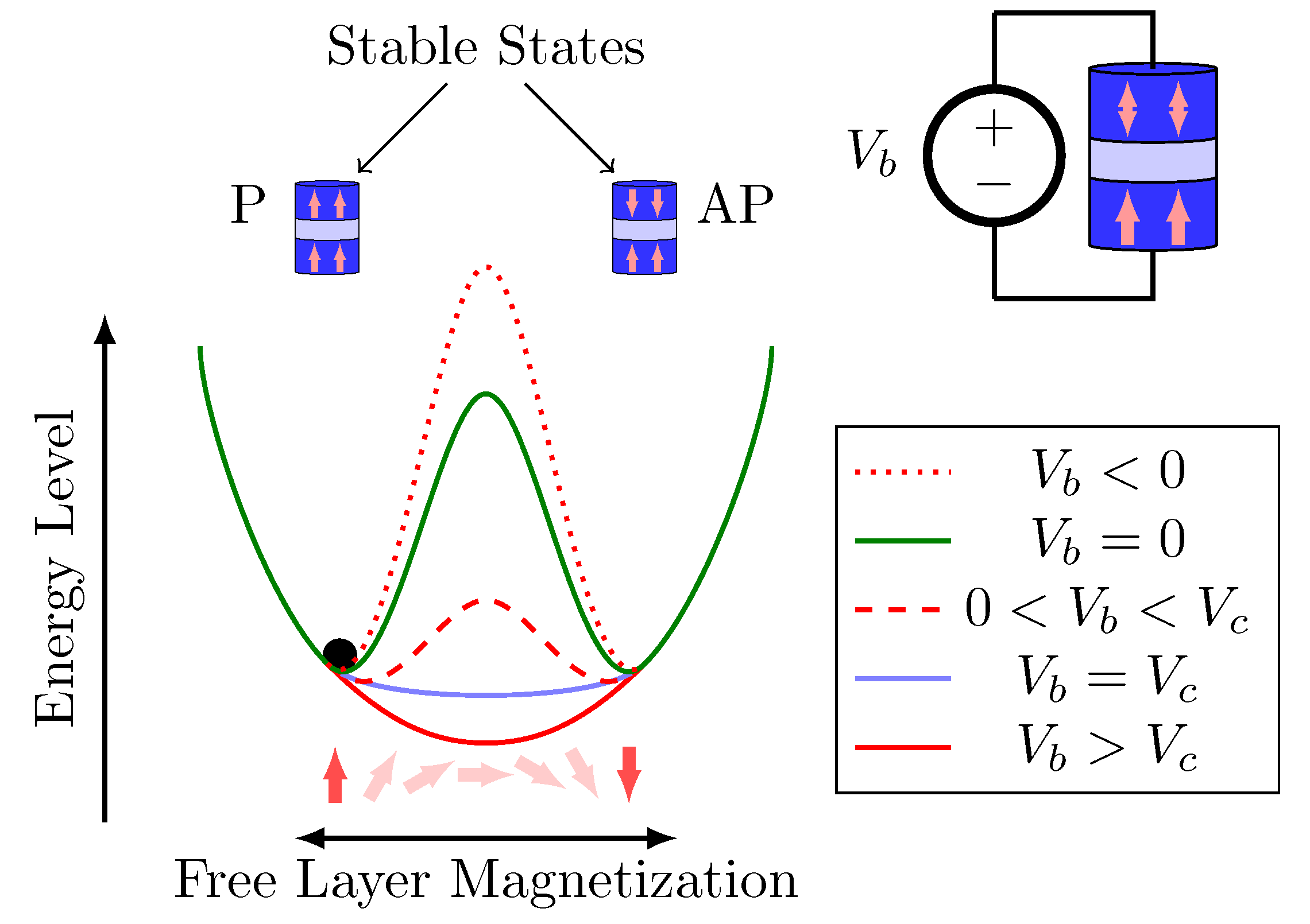
The operational characterization of VCMA-MTJ is illustrated in Figure 2. The magnetization orientations ( m z ) of the two ferromagnetic layers determine the resistance of the device ( R P in a parallel state and R A P in an anti-parallel state).
There are three switching mechanisms in VCMA-MTJ: thermally assisted, precessional switching and STT-assisted precessional switching [6]. This work deals with the precessional VCMA.
Precessional VCMA switching is realized with a high positive switching voltage V b . The energy barrier E b between two stable magnetization states can be eliminated as the precessional VCMA switching when V b is greater than MTJ critical voltage V c . Equation (1) determines the minimum V c for successful VCMA-MTJ switching [9]:
V c = Δ ( 0 ) k B T t o x / ξ A ,
where Δ ( 0 ) is the thermal stability under zero voltage, ξ is the VCMA coefficient to weigh the perpendicular magnetic anisotropy (PMA) change under V b , t o x is the MTJ oxide layer thickness, A is the sectional area of the MTJ, k B is the Boltzmann constant, and T is the temperature.
After achieving the critical voltage V c , the VCMA-MTJ has its own dynamics that allows it to change continuously through its unstable states [2]. Once the excitation of its terminals is completed, the energy barrier of the intermediate states returns to a greater value than the stable states and the device tends to stabilize in one of the stable states (P or AP). To use the VCMA-MTJ in memory devices, a precise control of the writing process is required as will be discussed in Section 4.1.

3. SET Model

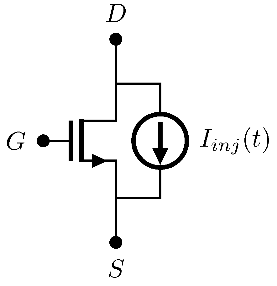
The most widely used model considers that an SET can be described by a double-exponential current pulse I i n j ( t ) on the transistor [26,27,28,29]. The current I i n j ( t ) is defined by Equation (2) where Q i n j is the charge injection level calculated by Equation (3), K is related to the material characteristics and the radiation intensity, τ 1 is the collection time constant for a junction, and τ 2 is the ion track establishment time constant [26,27,28]:
I i n j ( t ) = K . ( e t τ 1 e t τ 2 ) ,
Q i n j = I i n j ( t ) d t .
After a certain level of injected current, the voltage across the struck node can go beyond the power supply rails when the circuit-level SET simulations employ the independent current models. However, this is a physically not reasonable behavior and it represents a disadvantage of this model. As showed in [30], the SET current waveforms obtained from TCAD simulations do not go beyond the power supply rails.
From TCAD simulation, it can be seen that, for higher Linear Energy Transfer (LET) values, the SET-induced current pulse can not be well represented by a simple double-exponential expression [30,31]. It has a plateau region after a very short high-amplitude current peak when higher levels of charge are generated [31]. To deal with this issue, some voltage-dependent SET current models have been developed [30,32,33,34].
In this work, SET is generated by a voltage-dependent current model based on conventional double-exponential current pulse on the transistor taking into account the voltage across the node [34]. The current I i n j ( t ) is defined by Equation (4), where V D S denotes the voltage between the drain and the source of the transistor. Figure 3 shows the current source and transistor modelling SET event.
I i n j ( t ) = K . V D S . ( e t τ 1 e t τ 2 ) .
Figure 4 shows I i n j and V D when an SET with Q i n j = 1 f C reaches the access transistor. It can be seen that, when Equation (2) is used to represent I i n j (curves in red), a strange phenomenon appears in V D . In other words, for some time, V D < 0 shows an erratic behavior, and the voltage goes beyond the power supply rails. On the other hand, this behavior does not occur when Equation (4) is used to simulate I i n j (curves in blue).

4. Simulations and Results

4.1. VCMA-MTJ Based MeRAM Bit-Cell

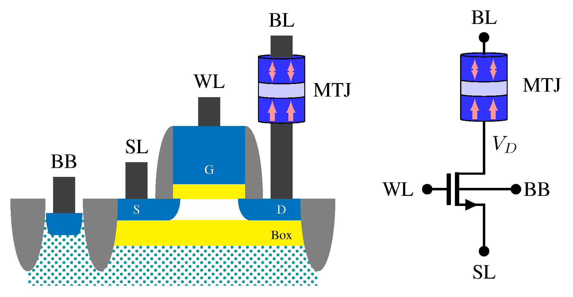
A 28 nm CMOS FDSOI design-kit is utilized to implement and simulate the VCMA-MTJ based MeRAM bit-cell illustrated in Figure 5. An 1T-1MTJ MeRAM bit-cell consists of an access transistor and an MTJ. In the 1T-1MTJ MeRAM architecture, the MTJ and the access transistor are located in series. The transistor’s gate is connected to the word-line (WL), the transistor’s drain to the bit-line (BL) crossing the MTJ and the transistor’s source to the source-line (SL).
Writing in a VCMA-MTJ based MeRAM can be considered as follows: either maintaining the MTJ state or switching it. A state check of the MTJ that guides the decision to switch or maintains the state of the MTJ would involve a circuit more complex than the bit-cell.
The performance of the memory device can be influenced by an SET occurrence on the access transistor leading to write failures [9,35]. Write failures occur when the MTJ in the bit-cell does not appropriately switch between parallel and anti-parallel states. In other words, because of the SET, the MTJ does not switch when it has to or the MTJ switches when it should not.
In order to analyze the vulnerability of the bit-cell against SET, this work considers a low threshold voltage (LVT) transistor as an access transistor with width W = 80 nm. This flipped-well configuration is usually used to improve the power-delay performance [36].
Table 1 lists the design parameters of VCMA-MTJ compact model [37]. The VCMA has two stable opposite states, parallel and anti-parallel, represented by m z 1 and m z 1 , respectively.
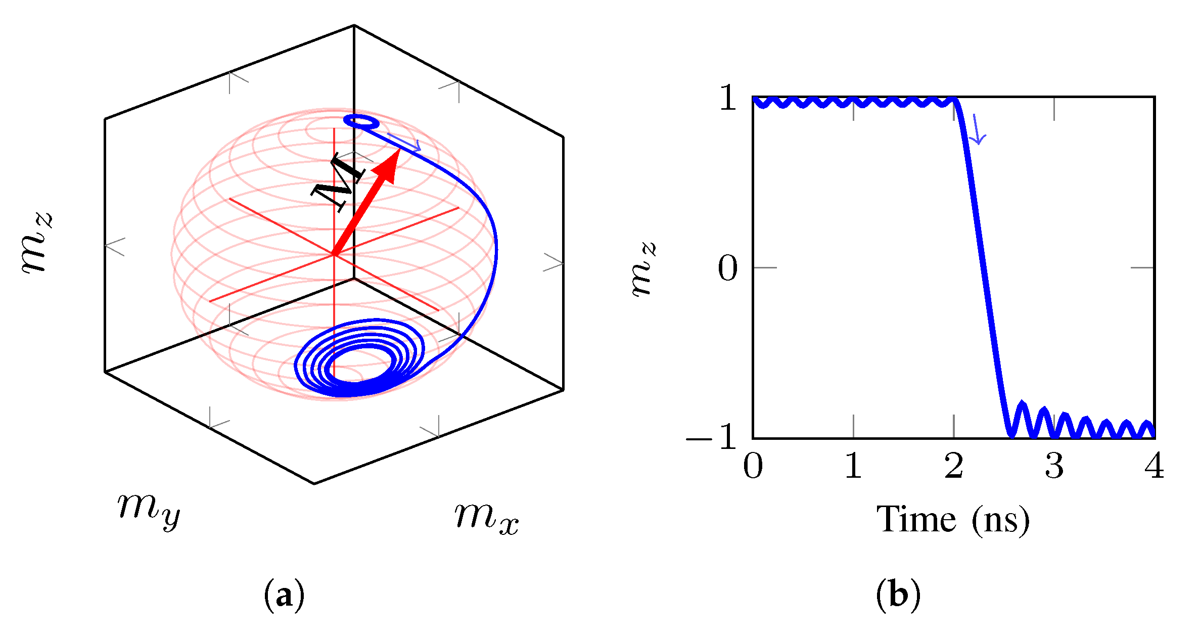
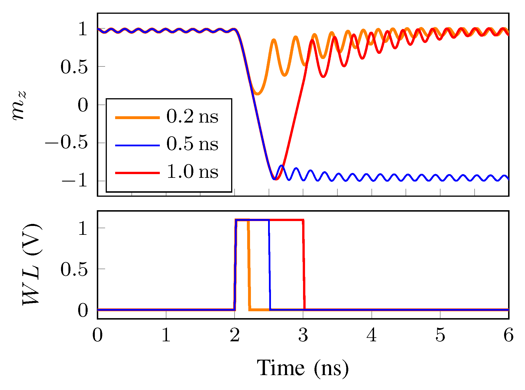
Although normally the write pulse is applied in the BL, the authors in [38] showed that applying the write pulse in the WL leads to a better pulse shape compared to when the write pulse is applied in the BL of the MeRAM. Moreover, it improves the switching probability and minimizes the area overhead (e.g., driver size) [38]. Figure 6 gives an example of the precession of magnetization under the influence of a voltage between the MTJ’s terminals. Due to the fluctuation of magnetization, the initial state of the free layer magnetic moment (represented by the angle between M and m z ) is different at each measurement. This leads to the stochastic reversal of free layer magnetization. As can be seen in Figure 6, M had m z value approximately equal to 1 before a write pulse occurs in WL (at 2 ns). The pulse lasted 0.5 ns and it was sufficient to change the M position from m z 1 to m z 1 .
In this work, the voltage pulse delay and the voltage pulse duration were analyzed to guarantee a successful writing considering V D D = V B L V S L = 1.1 V.
One of the intrinsic characteristics of the MTJ is a small variation of its state related to the fluctuation of the magnetization of the free layer magnetic moment. The circuit in which the MTJ is inserted could not be as fast as these variations that could be in the order of multiple GHz’s. Therefore, an SET robustness analysis must take into account this peculiar behavior of the MTJ magnetic state.
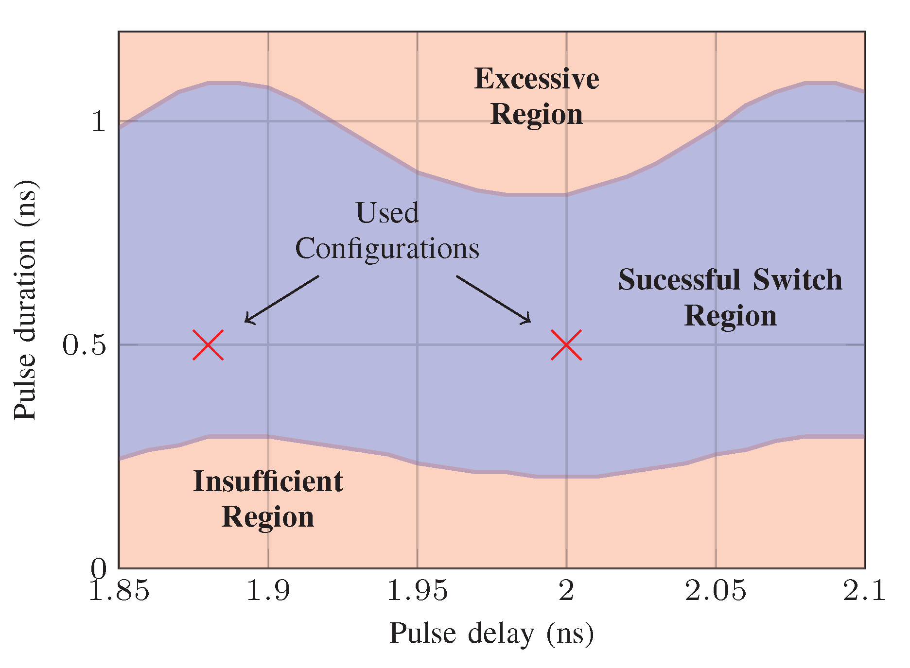
Figure 7 illustrates this variation of state and its effects on possible switching failures. It can be seen that a successful writing (represented by the “successful switch region” in Figure 7) depends on the voltage pulse amplitude, duration, and the instant in which the voltage pulse is applied.
Voltage pulses with various durations are studied to explore the switching characteristics. Figure 8 presents the time dependence of m z when a pulse with delay of 2 ns is applied with different voltage pulse durations. From Figure 7 and Figure 8, it can be noticed that the voltage pulse has to have a minimum duration to lead to a successful switch. If the voltage pulse duration is relatively short (represented by the “insufficient region” in Figure 7 and the orange curve in Figure 8), m z can not switch and m z goes back to the initial stage. On the other hand, if it has a longer pulse duration (represented by the “excessive region” in Figure 7 and the red curve in Figure 8), initially m z changes to the other state but then it switches back to the initial state, so, in the end, the desirable switch will not occur. Therefore, to achieve deterministic MTJ switching, a precise control of the voltage pulse duration is required, that is, a shorter or longer voltage pulse duration may cause a switching failure.
In this work, the voltage pulse amplitude and duration were properly selected based on the results presented in Figure 7. Two different voltage pulses for writing are considered in the SET effects analysis. They were chosen taking into account the small state variations of the MTJ magnetic state so that possible effects related to the small difference in the synchronism between the write pulse delay and MTJ state can be analyzed. These chosen configurations are pointed out in Figure 7. In both cases, the voltage pulse duration is 0.5 ns.

4.2. SET Analysis

For writing each bit in an 1T-1MTJ cell, a voltage is applied through the MTJ and the free layer will change its state (P → AP or AP → P). The resulted voltage bias from BL to SL must be carefully considered to ensure the correctness of the operations.
Eventually, radiation could induce some possible write failure. A write failure could be caused by a particle strike on the access transistor of any line. The occurrence of an SET is independent of the device operation. Therefore, it is important to consider the circuit vulnerability against SET at any time during the entire operation of the circuit.
Critical charge Q c is denoted as the minimum SET charge that leads to an undesirable MTJ state switching when it reaches the access transistor. It can occur due to an insufficient or an excessive excitation of MTJ magnetic vector M in the free layer with the objective of changing the stable state.
In this work, it is considered that an SET reaches the access transistor of the bit-cell. In other words, a current pulse modeling SET is applied to the access transistor at different times with different charges to analyze which charge value would lead to an error in the MTJ stored state. An analysis of the failure in the MTJ state switching caused by the effects of the radiation is relevant for the development of MeRAM architectures more robust against SET. Simulations were carried out to identify the sensitivity of the circuit against SET considering three cases.

4.2.1. Case 1: Without Write Pulse

It is considered that there is no write pulse. In other words, Q c is the minimum SET charge that leads to an undesirable switching of MTJ state without a write request has been made. It is also equivalent to writing in an adjacent bit-cell. For Case 1, the write failure is only due to the radiation.
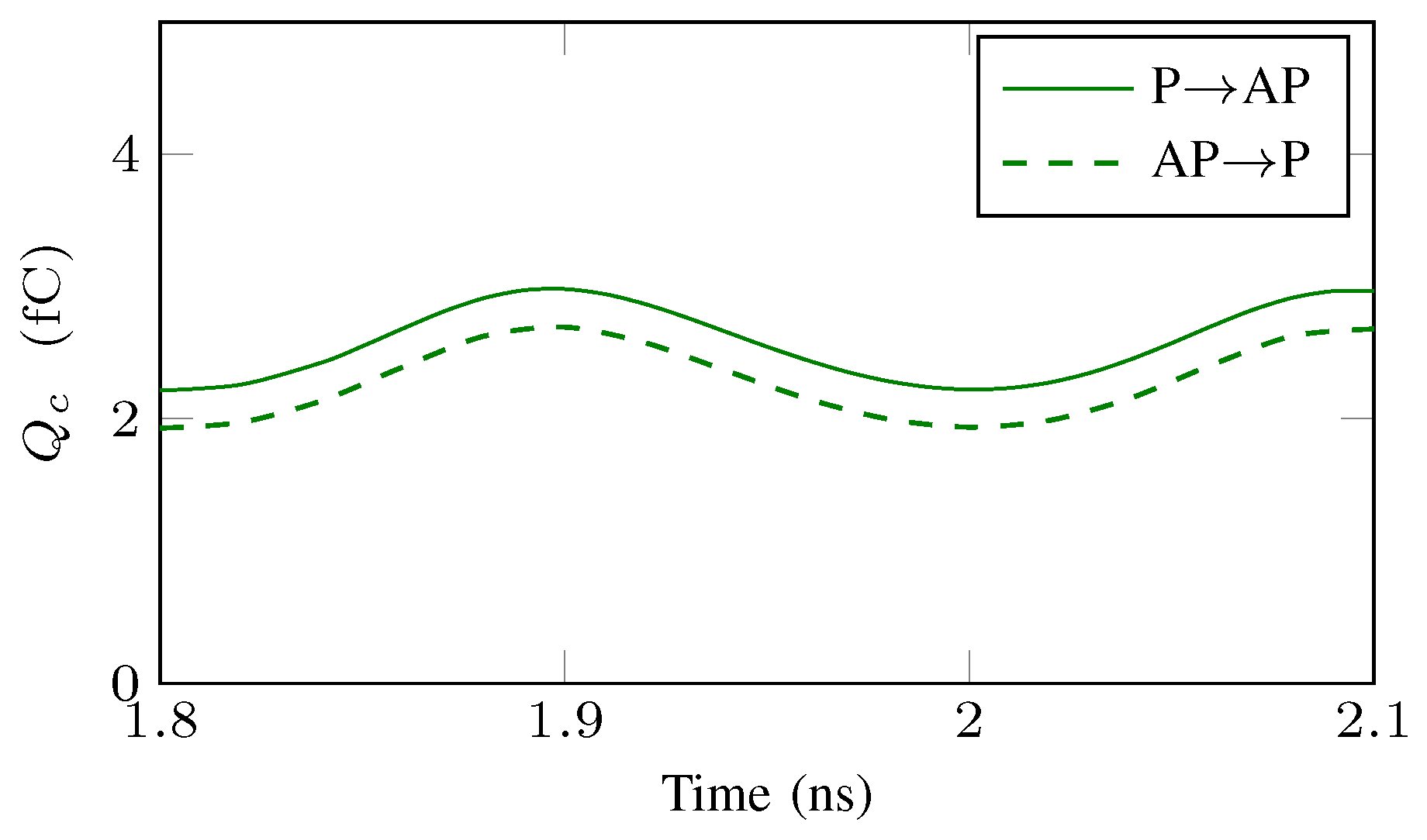
Figure 9 shows the Q c value for the scenario in which there is no write pulse, that is, there is no intention of writing in this bit-cell. It can be seen that, if an SET charge greater than 1.93 fC reaches the access transistor, an undesirable switch A P P can occur. On the other hand, if the MTJ is in the P state, an SET charge at least greater than 2.21 fC will be necessary to lead to an undesirable switch P A P . Figure 9 shows how Q c depends on the strike time moment. In the worst case, Q c = 1.93 fC.

4.2.2. Case 2: With Write Pulse

The minimum charge Q c is analyzed when there is an intention of writing in this bit-cell, that is, when there is a write pulse. In this scenario, a write failure occurs when there is no switch after the writing process. In this case, the write failure is due to the radiation combined with the voltage pulse.
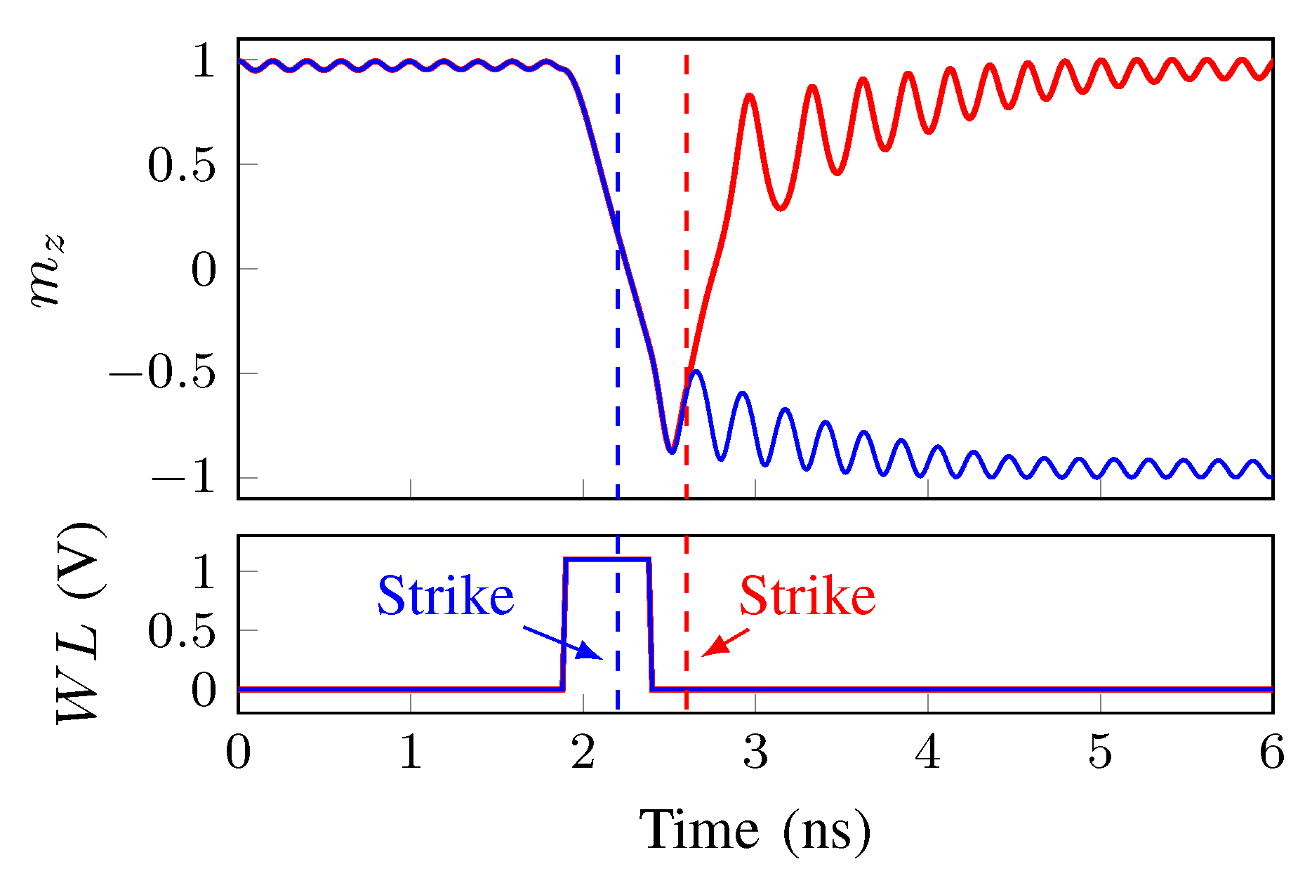
Figure 10 shows the time dependence of m z when an SET with Q i n j = 1 fC reaches the access transistor at 2.2 ns (blue curve) and 2.6 ns (red curve) for a voltage pulse delay of 1.88 ns. It can be noticed that when the SET occurs after the end of the voltage pulse (red curve), there is no switch, which means a writing error occurrence. Comparing with Figure 9, Figure 10 shows that the circuit is less SET robust when there is a write pulse. In other words, when there is a write pulse, a low SET charge ( Q i n j = 1 fC) can lead to a write failure while in the case in which there is no write pulse, a Q i n j > 1.93 fC (see Figure 9) is necessary to lead to a write failure.
As can be seen in Figure 10, the striking time influences the circuit behavior. In order to analyze this influence, the SET charge in the access transistor was varied to find the critical charge Q c required to lead to an error at different striking times.
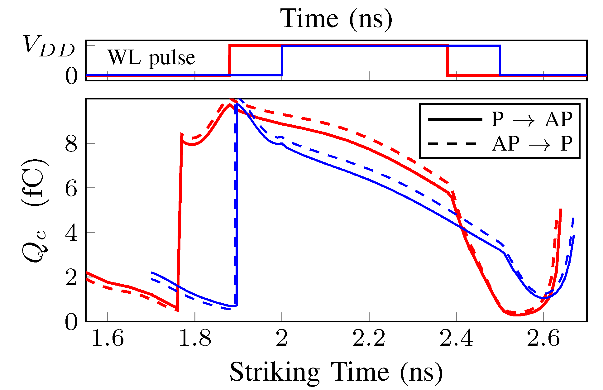
Figure 11 shows the Q c value as a function of the striking time when the voltage pulse delay is 1.88 ns (red curves) and 2 ns (blue curves). In both cases, the voltage pulse duration is 0.5 ns. In Figure 11 and Figure 12, the continuous lines represent the simulations of the transition P A P , while the dashed lines denote the simulations of the transition A P P .
From Figure 11, it can be noticed that, when the SET reaches the access transistor during the pulse duration, a very high Q c value is necessary to have an unsuccessful switch. This confirms the high resistance and robustness of the MeRAM write circuit to an SET radiation event during the write pulse. On the other hand, if the SET reaches the access transistor before or after the write pulse, a much lower Q c value can lead to an unsuccessful switch (write failure).
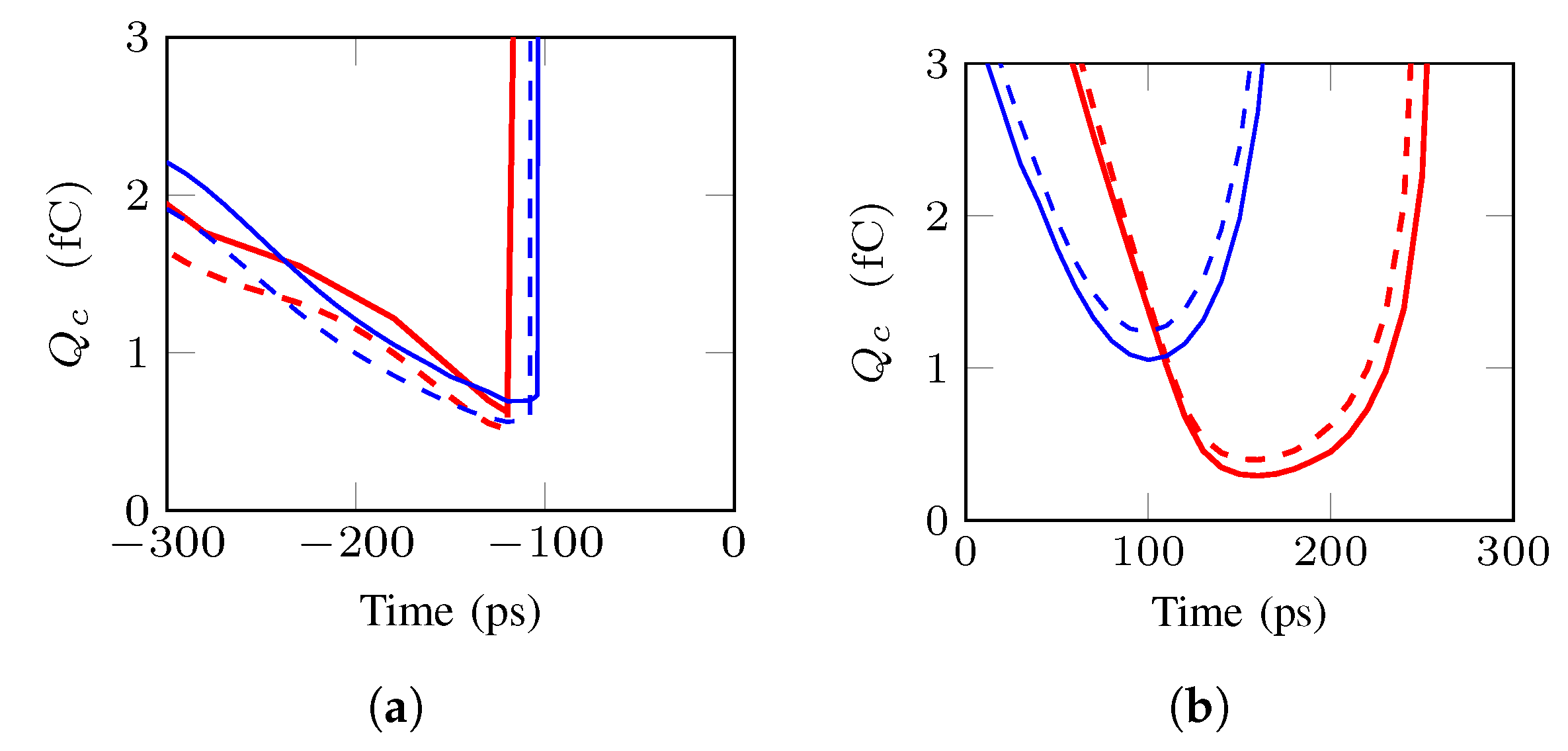
Figure 12a,b show the Q c value for the time just before the beginning of the voltage pulse and just after the end of the voltage pulse, respectively. The referenced times (0 ps) represent the beginning of the voltage pulse in Figure 12a and the end of the pulse in Figure 12b.
The results show that the robustness of the bit-cell against SET is highly dependent on the striking time. Moreover, the writing process is less robust against SET effects when the SET occurs close to the voltage pulse occurrence (before or after the write pulse). Considering these simulations, when an SET occurs before the write pulse, the worst critical charge was Q c 0.5 fC for both configurations (Figure 12a). It is basically four times lower than the Q c required when there is no write pulse (Figure 9). On the other hand, for an SET occurrence after the write pulse, while in one case Q c = 1.05 fC (blue curve) can lead to a write failure, values as low as Q c = 0.29 fC (red curve) can result in a writing error in the other case, showing a significant decrease of the circuit robustness against SET (Figure 12). This is more than six times lower than the Q c value in the case in which there is no write pulse (Figure 9).
The results show that, even if it has some advantages to apply the pulse in BL [38], it is important that the other writing lines (BL and SL) are not activated much before the beginning of the WL pulse (worst Q c at 100 ps before—see Figure 12a). In addition, BL and SL should be deactivated as soon as possible, that is, not much after of the end of the WL pulse (worst Q c at just over 150 ps—see Figure 12b). Those measures can contribute decisively to increase the robustness of the write operation in the bit-cell against SET. In other words, even if an SET reaches the access transistor, a current coming from an SET that crosses the MTJ would not be boosted by the difference of potential between BL and SL.

4.2.3. Case 3: Modulation of the Transistor Channel Width (W)

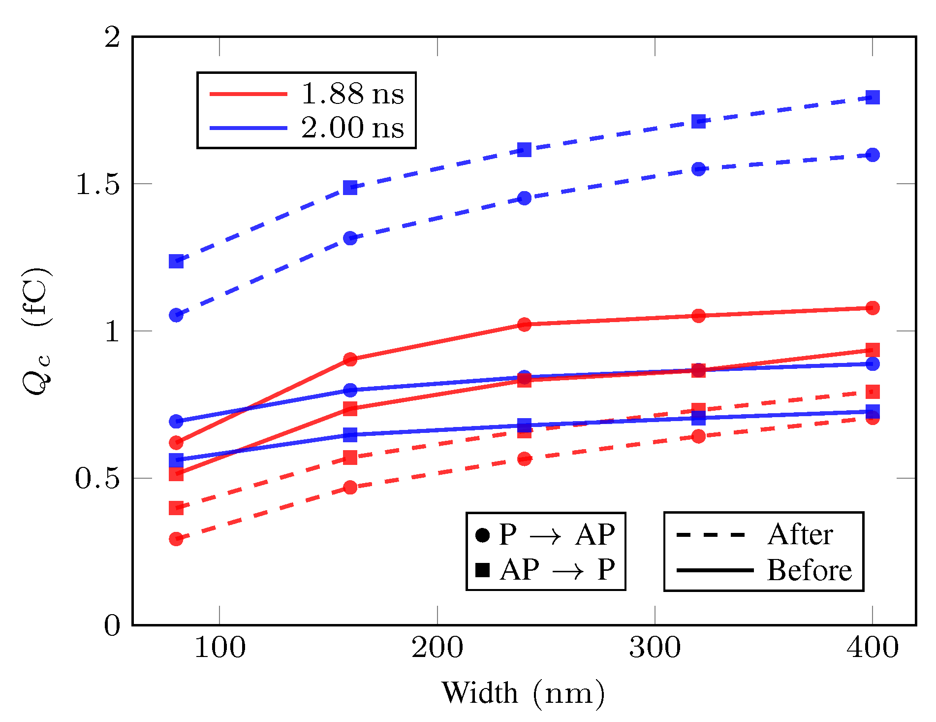
The SET robustness was analyzed varying the width W of the access transistor for voltage pulses with delays of 1.88 ns and 2 ns as shown in Figure 13. The worst Q c values that lead to a write failure considering an SET before and after the write pulse for the transitions P A P and A P P are presented in Figure 13. It can be seen that, with the increase of the W value, the circuit is more robust againt SET, that is, Q c is bigger. Moreover, varying the W value, the importance of taking into account variations of the instant of the pulse in relation to the magnetic state of the MTJ is highlighted. For example, regarding only the most critical points, when the delay is 1.88 ns (red curves), the Q c can increase from 0.29 fC ( W = 80 nm) to 0.70 fC ( W = 400 nm) which would mean an increase in robustness relative to the minimum Q c of more than 140 % . On the other hand, if the delay is 2 ns (blue curves), the gain of robustness is smaller, Q c varies from 0.56 fC ( W = 80 nm) to 0.72 fC ( W = 400 nm), that is, about 30 % .
It is also worth mentioning that, as the size W of the access transistor increases, inferences about the increase in SET robustness may change in relation to the critical Q c . For example, while with W = 80 nm the most critical point when the SET occurs before the write pulse (continuous curves in Figure 13) is associated with the delay of 1.88 ns, for bigger W values, the critical part is related to the delay 2 ns.
On the other hand, it can be seen in Figure 13 that, when the SET pulse occurs after the end of the write pulse (dashed curves in Figure 13), the greatest disparity in terms of critical charge variance appears. That is, if the analysis has been made only by considering a possible SET after the end of the write pulse, the conclusions could mask a minimum Q c value of 0.29 fC (delay 1.88 ns and W = 80 nm) by 1.05 fC (delay 2 ns and W = 80 nm), which would mean an erroneous analysis of the SET robustness more than three times.
The results presented in Figure 13 highlight that resizing the width of the access transistor can increase the robustness of the circuit against SET. However, it is worth remembering that larger transistors also mean overhead in the circuit area. The importance of the temporal analysis done in this work is also clear, not only between the striking time and the write pulse, but also the one of the write pulse moment and the minimum fluctuations of the MTJ.
The above results expose that an attention to the circuitry surrounding the write pulse generation is necessary to not create more critical points in the circuit with an MTJ in terms of SET robustness. The analysis of the SET impact allows for checking whether the circuit complies with the application requirements. If the circuit is not robust enough, Q c results enable pointing out the inferior limit of radiation that the circuit will support without error and then implement effective reliability improvement strategies such as resizing the access transistor.

5. Conclusions

This work addressed the problem of SET impact on a VCMA-MTJ based MeRAM bit-cell during the writing process. SET effects on a VCMA-MTJ based MeRAM bit-cell in a 28 nm FDSOI CMOS technology were evaluated considering the striking time. The minimum amount of charge required to produce an incorrect writing was analyzed. With this information, effective reliability improvement strategies can be implemented. Moreover, the results show the striking time dependence on the robustness of the circuit against SET. If the SET occurs close in time to the voltage write pulse, the VCMA-MTJ based MeRAM bit-cell can lose robustness against SET effects. Furthermore, when the width W of the access transistor increases from 80 nm to 400 nm, the minimum Q c value can increase by 1.4 times leading the circuit to be more robust against SET.
This work also intends to show possible care that should be taken into account in the architectures that use the new spintronics devices. Such devices are clearly interesting solutions in terms of energy consumption. However, it is important that new memories do not leave aside considerations that may arise due to the new characteristics of the dynamics of these devices.
The next steps of this work include inserting, in the simulations, the effects of thermal fluctuations characteristic of this device and other magnetic memory applications in which VCMA properties are used. In addition, the vulnerability of the memory device when an SET reaches other transistors of sensing and write circuits will be analyzed.

Author Contributions

N.M. performed the modeling and analysis. The manuscript was written by N.M. and E.C.M. L.N. and H.C. supervised the work. All authors took part in the paper edition.

Funding

This research was funded by Télécom ParisTech and Fondation de Coopération Scientifique Campus Paris Saclay (Project SpinTCAM, convention FCS 2017-0053D).

Conflicts of Interest

The authors declare no conflict of interest.

Abbreviations

The following abbreviations are used in this manuscript:
APAnti-Parallel
BLBit-Line
CMOSComplementary Metal Oxide Semiconductor
FDSOIFully Depleted Silicon-on-Insulator
LETLinear Energy Transfer
LVTLow Threshold Voltage
MeRAMMagnetoelectric Random Access Memory
MOSMetal Oxide Semiconductor
MRAMMagnetic Random Access Memory
MTJMagnetic Tunnel Junction
NVMNon-Volatile Memory
PParallel
PMAPerpendicular Magnetic Anisotropy
SETSingle-Event Transient
STTSpin Transfer Torque
TCADTechnology computer-aided design
TMRTunnel Magnetoresistance
VCMAVoltage-Controlled Magnetic Anisotropy
WLWord-Line

References

  1. Chappert, C.; Fert, A.; Dau, F.N.V. The emergence of spin electronics in data storage. Nat. Mater. 2007, 6, 813–823. [Google Scholar] [CrossRef] [PubMed]
  2. Kang, W.; Chang, L.; Zhang, Y.; Zhao, W. Voltage-controlled MRAM for working memory: Perspectives and challenges. In Proceedings of the Design, Automation Test in Europe Conference Exhibition (DATE), Lausanne, Switzerland, 27–31 March 2017; pp. 542–547. [Google Scholar]
  3. Maruyama, T.; Shiota, Y.; Nozaki, T.; Ohta, K.; Toda, N.; Mizuguchi, M.; Tulapurkar, A.A.; Shinjo, T.; Shiraishi, M.; Mizukami, S.; et al. Large voltage-induced magnetic anisotropy change in a few atomic layers of iron. Nat. Nanotechnol. 2009, 4, 158–161. [Google Scholar] [CrossRef] [PubMed]
  4. Shiota, Y.; Nozaki, T.; Bonell, F.; Murakami, S.; Shinjo, T.; Suzuki, Y. Induction of coherent magnetization switching in a few atomic layers of FeCo using voltage pulses. Nat. Mater. 2012, 11, 39–43. [Google Scholar] [CrossRef] [PubMed]
  5. Sharmin, S.; Jaiswal, A.; Roy, K. Modeling and design space exploration for bit-cells based on voltage-assisted switching of magnetic tunnel junctions. IEEE Trans. Electron Devices 2016, 63, 3493–3500. [Google Scholar] [CrossRef]
  6. Kang, W.; Ran, Y.; Zhang, Y.; Lv, W.; Zhao, W. Modeling and exploration of the voltage-controlled magnetic anisotropy effect for the next-generation low-power and high-speed MRAM applications. IEEE Trans. Nanotechnol. 2017, 16, 387–395. [Google Scholar] [CrossRef]
  7. Wang, S.; Lee, H.; Ebrahimi, F.; Amiri, P.K.; Wang, K.L.; Gupta, P. Comparative Evaluation of Spin-Transfer-Torque and Magnetoelectric Random Access Memory. IEEE J. Emerg. Sel. Top. Circuits Syst. 2016, 6, 134–145. [Google Scholar] [CrossRef]
  8. Yang, J.; Wang, P.; Zhang, Y.; Cheng, Y.; Zhao, W.; Chen, Y.; Li, H.H. Radiation-Induced Soft Error Analysis of STT-MRAM: A Device to Circuit Approach. IEEE Trans. Comput.-Aided Des. Integr. Circuits Syst. 2016, 35, 380–393. [Google Scholar] [CrossRef]
  9. Cai, H.; Wang, Y.; Kang, W.; Naviner, L.; Shan, W.; Yang, J.; Zhao, W. Enabling Resilient Voltage-Controlled MeRAM Using Write Assist Techniques. In Proceedings of the 2018 IEEE International Symposium on Circuits and Systems (ISCAS), Florence, Italy, 27–30 May 2018; pp. 1–5. [Google Scholar] [CrossRef]
  10. International Technology Roadmap for Semiconductors: Design. ITRS 2009 Edition. Available online: http://www.itrs2.net/itrs-reports.html (accessed on 15 December 2018).
  11. Pilia, R.; Bascoul, G.; Sanchez, K.; Mura, G.; Infante, F. Single Event Transient acquisition and mapping for space device Characterization. Microelectron. Reliab. 2016, 64, 73–78. [Google Scholar] [CrossRef]
  12. Kang, W.; Zhao, W.; Deng, E.; Klein, J.O.; Cheng, Y.; Ravelosona, D.; Zhang, Y.; Chappert, C. A radiation hardened hybrid spintronic/CMOS nonvolatile unit using magnetic tunnel junctions. J. Phys. D Appl. Phys. 2014, 47, 405003. [Google Scholar] [CrossRef]
  13. Bartra, W.C.; Vladimirescu, A.; Reis, R. FDSOI and Bulk CMOS SRAM Cell Resilience to Radiation Effects. Microelectron. Reliab. 2016, 64, 152–157. [Google Scholar] [CrossRef]
  14. Liu, R. Study of Radiation Effects on 28 nm UTBB FDSOI Technology. Ph.D. Dissertation, University of Saskatchewan, Saskatoon, SK, Canada, 2017. [Google Scholar]
  15. Bartra, W.C.; Vladimirescu, A.; Reis, R. Process and temperature impact on single-event transients in 28 nm FDSOI CMOS. In Proceedings of the 2017 IEEE 8th Latin American Symposium on Circuits Systems (LASCAS), Bariloche, Argentina, 30–23 February 2017; pp. 1–4. [Google Scholar] [CrossRef]
  16. Cai, H.; Wang, Y.; de Barros Naviner, L.A.; Liu, X.; Shan, W.; Yang, J.; Zhao, W. Addressing Failure and Aging Degradation in MRAM/MeRAM-on-FDSOI Integration. IEEE Trans. Circuits Syst. I Regul. Pap. 2018, 1–12. [Google Scholar] [CrossRef]
  17. Maciel, N.; Marques, E.C.; Naviner, L.A.B.; Cai, H. Single-Event Transient Effects on Dynamic Comparator in 28 nm FDSOI CMOS Technology. Microelectron. Reliab. 2018, 88, 965–968. [Google Scholar] [CrossRef]
  18. Zhang, D.; Zeng, L.; Zhang, Y.; Klein, J.O.; Zhao, W. Reliability-Enhanced Hybrid CMOS/MTJ Logic Circuit Architecture. IEEE Trans. Magn. 2017, 53, 1–5. [Google Scholar] [CrossRef]
  19. Deng, E.; Kang, W.; Zhang, Y.; Klein, J.; Chappert, C.; Zhao, W. Design Optimization and Analysis of Multicontext STT-MTJ/CMOS Logic Circuits. IEEE Trans. Nanotechnol. 2015, 14, 169–177. [Google Scholar] [CrossRef]
  20. Kang, W.; Deng, E.; Klein, J.; Zhang, Y.; Zhang, Y.; Chappert, C.; Ravelosona, D.; Zhao, W. Separated Precharge Sensing Amplifier for Deep Submicrometer MTJ/CMOS Hybrid Logic Circuits. IEEE Trans. Magn. 2014, 50, 1–5. [Google Scholar] [CrossRef]
  21. Cai, H.; Wang, Y.; de Barros Naviner, L.A.; Yang, J.; Zhao, W. Exploring Hybrid STT-MTJ/CMOS Energy Solution in Near-/Sub-Threshold Regime for IoT Applications. IEEE Trans. Magn. 2018, 54, 1–9. [Google Scholar] [CrossRef]
  22. Berger, L. Emission of spin waves by a magnetic multilayer traversed by a current. Phys. Rev. B 1996, 54, 9353–9358. [Google Scholar] [CrossRef]
  23. Wang, W.; Li, M.; Hageman, S.; Chien, C. Electric-field-assisted switching in magnetic tunnel junctions. Nat. Mater. 2012, 11, 64–68. [Google Scholar] [CrossRef] [PubMed]
  24. Barnes, S.E.; Ieda, J.I.; Maekawa, S. Rashba spin–orbit anisotropy and the electric field control of magnetism. Sci. Rep. 2014, 4, 1–5. [Google Scholar] [CrossRef]
  25. Velev, J.P.; Jaswal, S.S.; Tsymbal, E.Y. Multi-ferroic and magnetoelectric materials and interfaces. Philos. Trans. R. Soc. A Math. Phys. Eng. Sci. 2011, 369, 3069–3097. [Google Scholar] [CrossRef] [Green Version]
  26. Messenger, G.C. Collection of Charge on Junction Nodes from Ion Tracks. IEEE Trans. Nucl. Sci. 1982, 29, 2024–2031. [Google Scholar] [CrossRef]
  27. Singh, M.; Koren, I. Fault-sensitivity analysis and reliability enhancement of analog-to-digital converters. IEEE Trans. Very Large Scale Integr. Syst. 2003, 11, 839–852. [Google Scholar] [CrossRef] [Green Version]
  28. Malherbe, V.; Gasiot, G.; Soussan, D.; Autran, J.; Roche, P. On-Orbit Upset Rate Prediction at Advanced Technology Nodes: A 28 nm FD-SOI Case Study. IEEE Trans. Nucl. Sci. 2017, 64, 449–456. [Google Scholar] [CrossRef]
  29. Malherbe, V.; Gasiot, G.; Soussan, D.; Patris, A.; Autran, J.; Roche, P. Alpha soft error rate of FDSOI 28 nm SRAMs: Experimental testing and simulation analysis. In Proceedings of the 2015 IEEE International Reliability Physics Symposium, Monterey, CA, USA, 19–23 April 2015; pp. SE.11.1–SE.11.6. [Google Scholar] [CrossRef]
  30. Kauppila, J.S.; Sternberg, A.L.; Alles, M.L.; Francis, A.M.; Holmes, J.; Amusan, O.A.; Massengill, L.W. A Bias-Dependent Single-Event Compact Model Implemented Into BSIM4 and a 90 nm CMOS Process Design Kit. IEEE Trans. Nucl. Sci. 2009, 56, 3152–3157. [Google Scholar] [CrossRef]
  31. Kobayashi, D.; Makino, T.; Hirose, K. Analytical Expression for Temporal Width Characterization of Radiation-induced Pulse Noises in SOI CMOS Logic Gates. In Proceedings of the IEEE International Physics Reliability Symposium, Montreal, QC, Canada, 26–30 April 2009; pp. 165–169. [Google Scholar]
  32. Fulkerson, D.E.; Vogt, E.E. Prediction of SOI Single Event Effects Using a Simple Physics Based SPICE Model. IEEE Trans. Nucl. Sci. 2005, 51, 2168–2174. [Google Scholar] [CrossRef]
  33. Black, D.A.; Robinson, W.H.; Wilcox, I.Z.; Limbrick, D.B.; Black, J.D. Modeling of Single Event Transients with Dual Double-Exponential Current Sources: Implications for Logic Cell Characterization. IEEE Trans. Nucl. Sci. 2015, 62, 1540–1549. [Google Scholar] [CrossRef]
  34. Clark, K.A.; Ross, A.A.; Loomis, H.H.; Weatherford, T.R.; Fouts, D.J.; Buchner, S.P.; McMorrow, D. Modeling single-event effects in a complex digital device. IEEE Trans. Nucl. Sci. 2003, 50, 2069–2080. [Google Scholar] [CrossRef] [Green Version]
  35. Fong, X.; Kim, Y.; Choday, S.H.; Roy, K. Failure mitigation techniques for 1T-1MTJ spin-transfer torque MRAM bit-cells. IEEE Trans. Very Large Scale Integr. Syst. 2014, 22, 384–395. [Google Scholar] [CrossRef]
  36. Wang, Y.; Cai, H.; Naviner, L.; Zhao, X.; Zhang, Y.; Slimani, M.; Klein, J.; Zhao, W. A process-variation-resilient methodology of circuit design by using asymmetrical forward body bias in 28 nm FDSOI. Microelectron. Reliab. 2016, 64, 26–30. [Google Scholar] [CrossRef]
  37. Long, M.; Zeng, L.; Gao, T.; Zhang, D.; Qin, X.; Zhang, Y.; Zhao, W. Self-Adaptive Write Circuit for Magnetic Tunneling Junction Memory with Voltage-Controlled Magnetic Anisotropy Effect. IEEE Trans. Nanotechnol. 2018, 17, 492–499. [Google Scholar] [CrossRef]
  38. Lee, H.; Lee, A.; Wang, S.; Ebrahimi, F.; Gupta, P.; Amiri, P.K.; Wang, K.L. A Word Line Pulse Circuit Technique for Reliable Magnetoelectric Random Access Memory. IEEE Trans. Very Large Scale Integr. Syst. 2017, 25, 2027–2034. [Google Scholar] [CrossRef]
Figure 1. Magnetic tunnel junction (MTJ).
Jlpea 09 00015 g001
Figure 2. Structure and stable states of the VCMA-MTJ device.
Jlpea 09 00015 g002
Figure 3. Modelling the SET in NMOS.
Jlpea 09 00015 g003
Figure 4. I i n j and V D when an SET with Q i n j = 1 f C reaches the access transistor. I i n j is defined by Equations (2) and (4) in the red and blue curves, respectively.
Jlpea 09 00015 g004
Figure 5. VCMA-MTJ based MeRAM bit-cell with Fully Depleted Silicon-on-Insulator (FDSOI) technology.
Jlpea 09 00015 g005
Figure 6. The precession of magnetization under the influence of a voltage between the MTJ’s terminals: (a) the reversal process of magnetic moment; (b) time dependence of m z .
Jlpea 09 00015 g006
Figure 7. Variation of write pulse on MTJ, from P state to AP state. The pink area denotes the switching failure.
Jlpea 09 00015 g007
Figure 8. Magnetization dynamics of the free layer from P state to AP state switching with different pulse durations.
Jlpea 09 00015 g008
Figure 9. Value of Q c when there is no write pulse.
Jlpea 09 00015 g009
Figure 10. The time dependence of m z when an SET with Q i n j = 1 fC reaches the access transistor at 2.2 ns and 2.6 ns.
Jlpea 09 00015 g010
Figure 11. Value of Q c for a voltage pulse delay of 1.88 ns and 2 ns.
Jlpea 09 00015 g011
Figure 12. Q c values related to: (a) the beginning of the voltage pulse with delays of 1 . 88 ns and 2 ns; (b) the end of the voltage pulse with delays of 1.88 ns and 2 ns.
Jlpea 09 00015 g012
Figure 13. Q c values for different width W.
Jlpea 09 00015 g013
Table 1. Design specification of the VCMA-MTJ compact model.
ParameterDescriptionValue
TTemperature300 K
TMR(0)TMR ratio at V b = 0 100 %
R P , R A P MTJ resistance100 k Ω , 200 k Ω
Δ ( 0 ) Thermal stability at V b = 0 40
V h 1 / 2 TMR Bias voltage 0.5 V
T o x MgO oxide thickness 1.4 nm
T f l Free layer thickness 1.1 nm
dMTJ diameter50 nm
α Damping factor 0.02
K i Interfacial PMA 0.32 × 10 3 J/m 2
M s Saturation magnetization 0.625 × 10 6 A/m
ξ VCMA coefficient60 fJ/V·m
H x External magnetic field400 Oe