Abstract
To meet the performance and scalability demands of the fast-paced technological growth towards exascale and big data processing with the performance bottleneck of conventional metal-based interconnects (wireline), alternative interconnect fabrics, such as inhomogeneous three-dimensional integrated network-on-chip (3D NoC) and hybrid wired-wireless network-on-chip (WiNoC), have emanated as a cost-effective solution for emerging system-on-chip (SoC) design. However, these interconnects trade off optimized performance for cost by restricting the number of area and power hungry 3D routers and wireless nodes. Moreover, the non-uniform distributed traffic in a chip multiprocessor (CMP) demands an on-chip communication infrastructure that can avoid congestion under high traffic conditions while possessing minimal pipeline delay at low-load conditions. To this end, in this paper, we propose a low-latency adaptive router with a low-complexity single-cycle bypassing mechanism to alleviate the performance degradation due to the slow 2D routers in such emerging hybrid NoCs. The proposed router transmits a flit using dimension-ordered routing (DoR) in the bypass datapath at low-loads. When the output port required for intra-dimension bypassing is not available, the packet is routed adaptively to avoid congestion. The router also has a simplified virtual channel allocation (VA) scheme that yields a non-speculative low-latency pipeline. By combining the low-complexity bypassing technique with adaptive routing, the proposed router is able to balance the traffic in hybrid NoCs to achieve low-latency communication under various traffic loads. Simulation shows that the proposed router can reduce applications’ execution time by an average of 16.9% compared to low-latency routers, such as SWIFT. By reducing the latency between 2D routers (or wired nodes) and 3D routers (or wireless nodes), the proposed router can improve the performance efficiency in terms of average packet delay by an average of (or ) in 3D NoCs (or WiNoCs).
1. Introduction
Recent advances in cyber physical systems (CPS) that seamlessly integrate autonomous automobile systems, advanced distributed robotics, medical monitoring (complex biological sensing, computation and actuation), transform engineering and life sciences into a quantitative, data-rich scientific domain. The large amount of heterogeneous data of high variability sensed from biological and/or non-biological entities of different forms paired with novel data types introduces several challenges to high-performance computing (HPC) systems at multiple dimensions. Networks-on-chip (NoC) overcome these challenges by exploiting the massive fine-grained parallelism and sustaining the inherent communication requirements of big data applications and exascale collective communications.
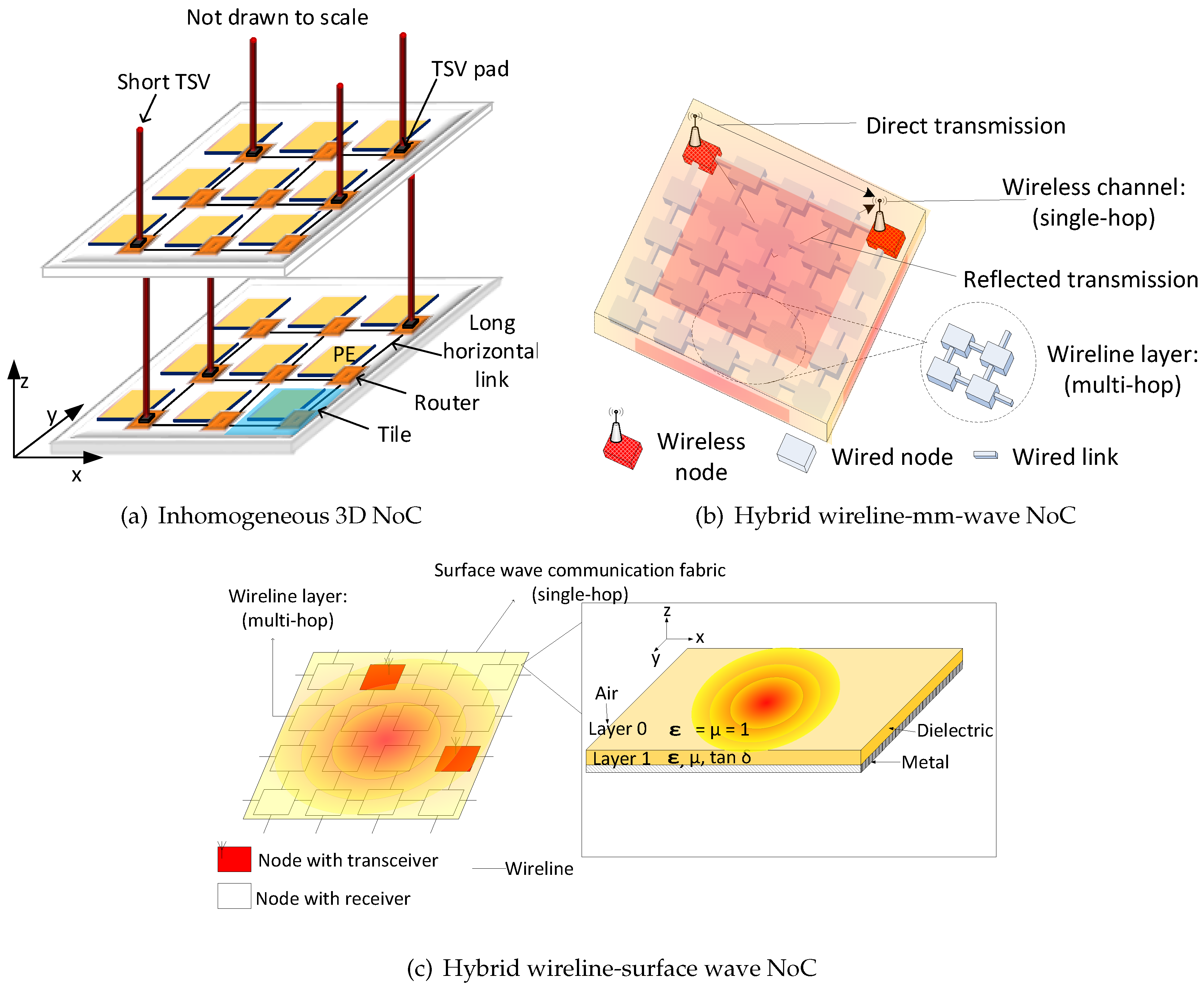
However, the slow multi-hop communication, as well as high power consumption and poor scalability with technology of the conventional metal-based interconnects have propelled the research for alternative fabrics as supplementary interconnects for communication among remote cores in modern system-on-chip (SoC) design. Recently, the optical interconnect has been investigated as an alternative communication fabric. However, optical networks suffer from high area overheads as they employ non-complementary metal oxide semiconductor (non-CMOS) components. On the other hand, three-dimensional integrated circuits (3D ICs) have alignment issues along with low yield and high temperature dissipation, which affect the reliability of the implemented SoC cores. Specifically, the 3D routers have a larger area and power consumptions than a 2D router with a similar architecture. To optimize the performance and manufacturing cost of 3D NoCs with minimal distortion to the modularity, inhomogeneous architectures have been proposed to combine 2D and 3D routers in 3D NoCs [1,2,3,4,5]. However, due to the limited number of 3D routers, inhomogeneous 3D NoCs have a performance trade-off. Alternatively, hybrid wired-wireless networks-on-chip (WiNoCs) have emerged to combine the global performance benefits of a CMOS-compatible wireless layer, as well as the short range low power and area benefits of the wireline communication fabric in NoCs. Two emerging wireless communication fabrics for WiNoCs are (1) the scalable millimetre wave (mm-wave), which relies on the free space signal radiation, and (2) the reliable 2D waveguide, where the signal is propagated in the form of the Zenneck surface wave (SW) on a specially-designed sheet, which is an inhomogeneous plane that supports electromagnetic wave transmission [6]. While inhomogeneous 3D NoCs, mm-wave and SW WiNoCs promise to resolve the poor scalability and performance issues of conventional wireline NoC design, the multi-hops among the long wired 2D routers are still a performance bottleneck. Our goal is to mitigate the performance reduction of such a communication fabric by proposing an efficient router architecture that accounts for the manufacturing cost in terms of area and power consumption.
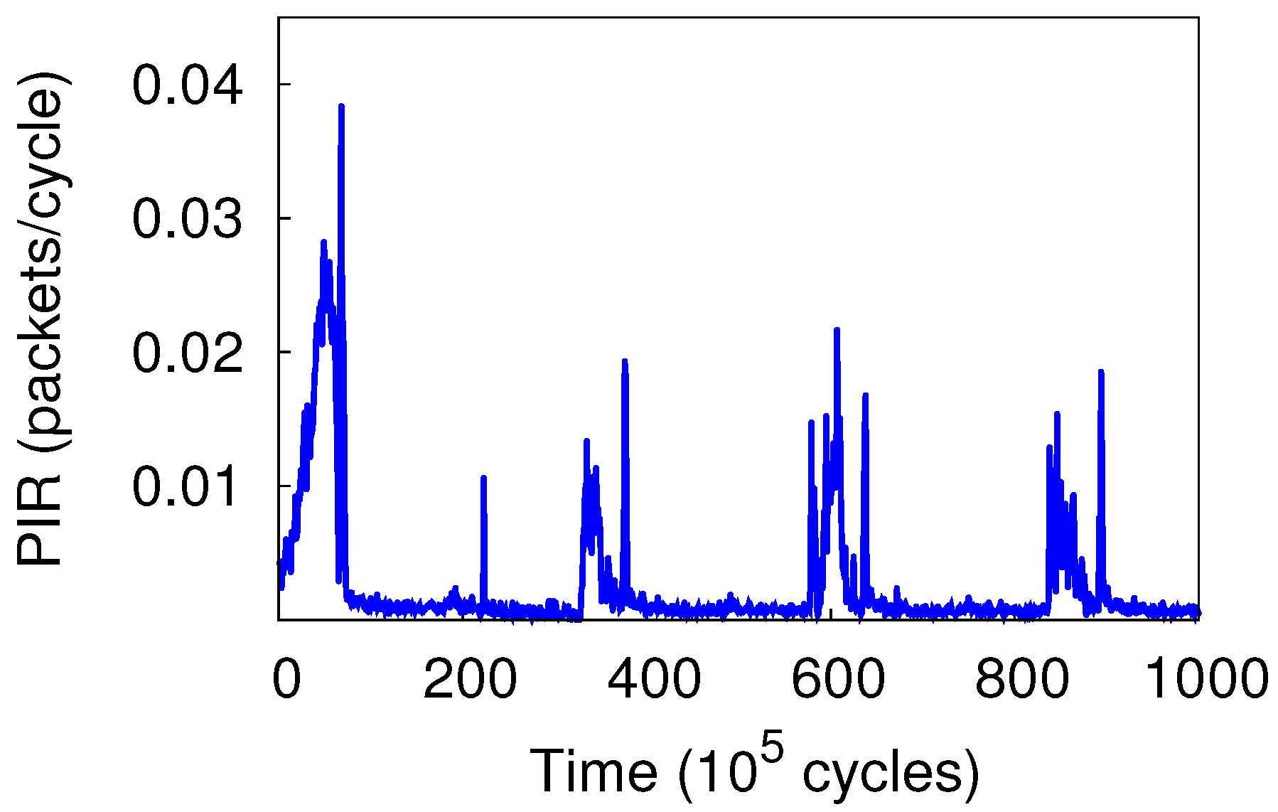
Traffic distribution in the chip multiprocessor (CMP) varies with workloads and is usually non-uniform, both temporally and spatially [7]. Figure 1 shows the packet injection rate (PIR) of a single node (Node 1) over time in the splash2-barnes [8] application simulated in Sniper [9] (configuration described in Section 4). It can be observed that the PIR varies at different times with records of both high and low PIRs. NoC of CMP should avoid high PIR areas and meanwhile exploit the idle networking resources of low-load areas when sending packets to reduce packet delay under such dynamic traffic loads.
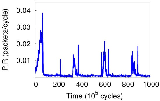
Figure 1.
Packet injection rate (PIR) of a single node over time in the splash2-barnes application.
Adaptive routing among 2D routers can reduce queuing delay at high loads. However, adaptive routing requires per-hop output port selection to avoid congestion in addition to the demand for a complex virtual channel allocation scheme to avoid deadlocks [10]. These operations lead to the non-ideal zero-load delays in conventional adaptive routers. Recently proposed networks [11,12] develop simpler pipelines to reduce zero-load latency. However, these designs perform poorly under high-load traffic. Moreover, these routers do not support the virtual channel (VC) to reduce complexity and pipeline latency. A low-complexity adaptive router that can avoid congestion yet maintain low zero-load latency is desirable for CMPs. CMP demands NoC to have both low queuing and pipeline delays under the non-uniform and dynamic traffic of CMP workloads. CMP also requires VC support to isolate messages of different classes. Moreover, inhomogeneous 3D NoCs (or WiNoCs) require the multi-hop 2D routers to deliver packets to the 3D routers (or wireless routers) with high efficiency to fully exploit the benefit of the short inter-layer wires (or single-hop wireless layer).
We propose SlideAcross, a three-stage adaptive VC-compatible router with a single-cycle bypassing mechanism to meet the communication needs of emerging communication fabrics for modern CMPs. The proposed router integrates adaptive routing with low-latency bypassing in a cost-effective way to overcome the drawbacks of existing adaptive routing and low-latency architectures.
The proposed router mainly consists of an input buffer, crossbar and allocators for the crossbar and virtual channel. In addition, there is a set of bypass datapaths to facilitate intra-layer traversal. The bypass datapath is extended from the low-cost dimension sliced router (DSR) [11]. A packet that takes advantage of bypass datapaths does not need to wait for crossbar setup and experiences single-cycle delay per hop (including link traversal). If bypassing is not available or not applicable for a packet, the packet is stored in an input buffer and then follows the adaptive routing pipeline. SlideAcross uses a simple VA scheme to allow VA to be performed after switch allocation (SA) in the same cycle non-speculatively. In brief, this paper proposes a non-speculative three-stage adaptive router and a low-complexity single-cycle bypassing mechanism to efficiently reduce the contention among the 2D routers and wireline layer for emerging inhomogeneous 3D NoCs and WiNoCs, respectively, that can handle the communication dynamics of various CMP workloads. In summary, in this paper:
- We propose a low-complexity single-cycle bypassing mechanism for adaptive routers without using sideband lookahead signals. The bypass datapath applies DoR on packets to exploit the pre-setup intra-dimension crossbar connections. Consequently, bypass paths help escape the long adaptive routing pipeline and effectively reduce packet delay at low loads. By introducing a dedicated VC in the router’s micro-architecture, the path delay for bypassing logic implemented in the 45-nm standard cell library was reduced by .
- We present a three-stage non-speculative high-throughput adaptive router that supports the proposed bypassing mechanism. By employing a tagging mechanism, the proposed router is able to either avoid congested nodes under high traffic conditions or employ the single-stage bypassing technique under low traffic conditions.
- We extend the performance of three promising communication fabrics for NoCs: low-cost 3D NoCs, mm-wave WiNoCs and surface wave WiNoCs. We replaced the slow 2D routers in inhomogeneous 3D NoCs (or multi-hop wired nodes in WiNoCs) with the proposed router to provide fast transfer between remote nodes and high performance nodes (3D routers or wireless routers).
- We perform cycle-accurate-based evaluations of the proposed router in high performance communication fabrics for NoCs and compare with emerging 3D NoCs, WiNoCs, as well as conventional low area wireline communication fabric. Even without any additional router port (as in the case of the SmallWorld network) or complex micro-architecture, the proposed router can reduce applications’ execution time of existing router architectures by an average of .
The rest of the paper is organized as follows. Section 2 introduces the background and existing efforts to reduce network latency. Section 3 presents the details of the proposed router architecture for improving the performance of hybrid NoCs. Section 4 evaluates the performance of the proposed router using synthetic traffic and realistic workloads. We also include area and power overhead estimation. In Section 5, we conclude this work.
2. Related Work
2.1. NoC Router Architecture and Algorithms
Scalable NoC contains a router at each hop to control access to shared resources. A classic NoC router [13] works as follows. The router first writes a received packet into buffer (BW) and computes the packet’s admissible output port at the same time (RC). Then virtual-channel allocation procedure assigns a free VC of the output channel for the packet. Upon successfully obtaining a VC, the packet arbitrates for accessing the crossbar ports (SA). If all is successful, the packet can go through the switch traversal (ST) and link traversal (LT) stage to proceed to a neighbour router [13]. Going through these stages in series causes large delay on each hop, which makes the communication inefficient. Moreover, if any of the desired resources (e.g., buffer, crossbar) cannot be obtained, a packet is stalled, increasing the packet delay. It is widely accepted that latency is one of the key challenges of designing practical on-chip networks [14]. To address this challenge, various techniques such as adaptive routing, parallel execution, link improvement and structure simplification, have been proposed.
Adaptive routing: Changing packet paths dynamically to avoid congestion reduces packet queuing delay effectively [15,16]. However, at low-load conditions, adaptive routing brings negligible improvement. Moreover, the required pipeline of adaptive routing has higher complexity.
Parallel execution: Some of the operations can be done in parallel. The work in [17] does VA and SA in parallel speculatively and prioritizes non-speculative packets in SA to increase resource utilization. The work in [18] exploits the abundant bandwidth inside the router and multicast flits to output ports speculatively rather than waiting for SA. Parallel processing of a packet can also happen on different routers with the help of control flits, which go ahead of data flits [19]. SA for a flit is done based on the control flit, while the data flit is traversing the link on the previous router. When the data flit arrives, it can bypass the SA stages and go directly to ST. However, the sideband network for control flits introduces extra wiring and power overhead.
Link improvement: Low-swing signalling [20] and an asynchronous link [21,22] have been adopted in NoCs to allow multiple-hop traversal in one cycle. Low-swing signalling has poor bandwidth density, and the asynchronous link can have signal skew issues due to interference [23]. In chips operating at high frequency, the signal traversal length can be limited due to the small clock cycle.
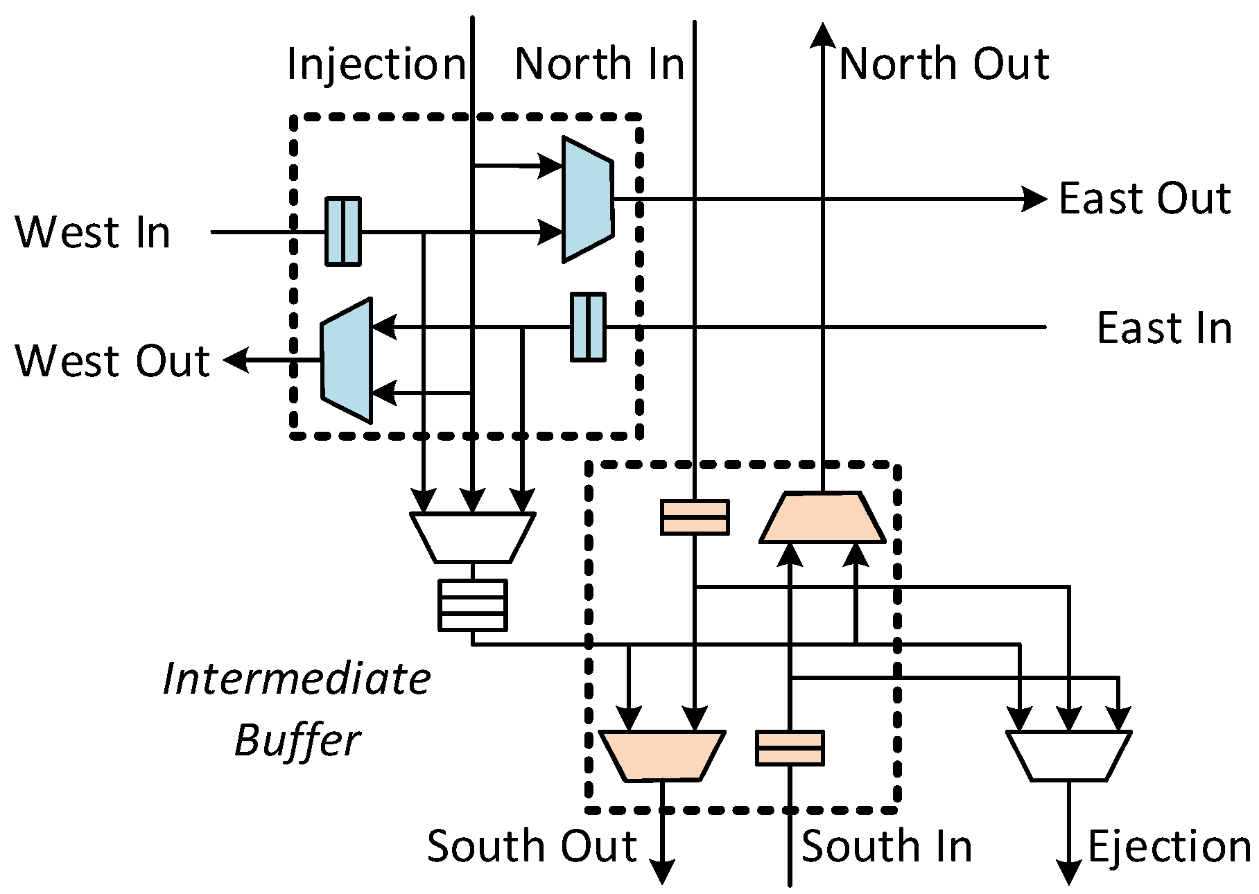
Structure simplification: The simplicity of the ring topology allows the router to have a simple and low-latency micro-architecture [12]. In 2D mesh topology, the dimension-sliced router (DSR) is proposed to reduce router cost and latency [11]. DSR abandons the input buffers of routers and decouples the datapath of the two dimensions to the reduce cost. Figure 2 shows the datapath of DSR, which supports dimension-ordered routing. Intra-dimension traversal in DSR incurs single-cycle delay (including link traversal).
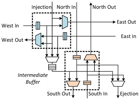
Figure 2.
Dimension-sliced router with single-cycle switch traversal (ST) + link traversal (LT) capability.
CMP workloads require low-latency adaptive routers to reduce communication latency and require VC support in NoC to achieve message isolation. Existing approaches that aim at reducing the latency of NoC routers such as lookaheads [24] add wiring and logic complexity to routers and increase NoC’s area overhead and power consumption. Speculation [17] does not reduce the worst-case pipeline delay.
Simple NoC micro-architectures, like [11,12], are not adaptive and have no VCs. High radix routers [25,26] usually have higher serialization delay and do not work well under adversarial traffic [22]. NoC with multi-hop traversal in single cycle capability, such as SMART [22], shows significant latency reduction. However, such a feature may not be sustained in chips operating at a high frequency, or with long links (e.g., hierarchical topology), or in the combination of two. In contrast, single-cycle-per-hop routers are still good candidates for such scenarios. In this paper, we propose a three-stage non-speculative adaptive VC router for CMP and develop a low-complexity single-cycle bypassing mechanism to reduce low-load latency without using sideband lookahead signals.
2.2. 3D Network-on-Chip
The evolution of SoC design to the third dimension offers many opportunities, such as the integration of inhomogeneous cores, which results in several challenges, including optimal inhomogeneous NoC topologies, router architectures and application mapping techniques [27]. A 3D router has a larger area and power consumption than a 2D router with similar architectures [28]. Particularly, the seven-port symmetric router has an area and power overhead of and , respectively, compared to a conventional five-port router [29]. Li et al. [30] proposed to replace the large seven-port symmetric 3D routers with the six-port NoC-Bus hybrid 3D routers. However, the hybrid router requires an additional central arbiter per each vertical pillar in the NoC. Moreover, the hybrid router still has a large crossbar and energy consumption. Xiangyu et al. [31] have demonstrated that the area overhead of TSVincreases with the increase in the number of 3D layers. Particularly, the area overhead of the TSV for a four-layer 3D NoC with five million gates can reach as high as . Similarly, Bartzas et al. [1] presented a study of the area, power and performance trade-off of combining 2D and 3D routers in 3D mesh and torus topologies. Xu et al. [32] performed an evaluation of the impact of reducing the number of TSVs to half and a quarter on the performance of 3D NoCs. Their proposed architectures, quarter/loand half/lo (quarter/hiand half/hi), aim at generating inhomogeneous 3D NoC with 2D routers placed as close to (far from) 3D routers as possible in each layer. Liu et al. [33] used partition islands of routers to constitute regions for sharing the same TSV pad for inter-layer communication controlled by serialization logic. However, serialization along the TSV bundle causes the average packet delay to increase exponentially as the number of routers per TSV bundle increases. Moreover, the TSV pads have no direct connection to the processing cores, which is a waste of chip area compared to our proposed architectures. Furthermore, the genetic algorithm and simulated annealing employed in [34] for the selection and placement of different TSV patterns (sharing regions) in 3D NoCs have an exponential complexity with a large design exploration space. Similarly, Pasricha [35] proposed a serialization technique for reducing the number of TSVs where the link size of TSVs at selected nodes is reduced by a fraction. Thus, if the number of TSVs exceeds a threshold, serialization is adopted to reduce the bandwidth of some TSVs. However, due to the reduced bandwidth of the TSVs and serialization logic, such architectures have high average packet latencies. Moreover, due to the higher overhead of the serialization receiver and transmitter logic compared to the TSV reduction, such architectures have even higher power consumption compared to the homogeneous 3D mesh. Based on the serialization methodology, Pasricha [36] proposed a 3D NoC synthesis framework; their approach adopt routers that have several local ports, which have high power consumption due to the increased number of ports and high data rates across the crossbar. On the other hand, existing inhomogeneous architectures (Figure 3a) [1,2,32,33,37,38,39,40,41,42] do not consider the dynamics of application traffic load in their inhomogeneous architectures. Applications in such 3D NoCs are not optimized, as communication bandwidth and performance constraints of the applications were not considered in the architecture generation. To resolve this, a systematic approach for generating inhomogeneous 3D NoC architectures where the TSV and buffer utilization of the given application are exploited is proposed in [3]. Though inhomogeneous 3D NoC architectures reduce the number of power (up to 67%) and area hungry 3D routers, as well as the number of TSVs, they inhibit the total performance of the NoC. Particularly, by reducing the number of 3D routers to , the average hop count and delay can increase up to and an average of , respectively, in 4 × 4 × 4 3D NoCs [43,44]. This paper aims to resolve the performance degradation introduced by the heterogeneity in the router architectures of existing inhomogeneous 3D NoCs while maintaining the small area of the 2D routers by introducing bypass links and adaptivity to escape the intra-layer multi-hop and congested regions.
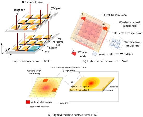
Figure 3.
Emerging high performance communication fabric chip multiprocessors (CMPs).
2.3. Millimetre-Wave vs. Surface Wave-Enabled WiNoCs
RF interconnect has low area and low power consumption due to its CMOS compatibility. However, RF interconnect relies on long transmission lines for guided data transmission, which requires alignment between transmission pairs. Alternatively, mm-wave has emerged as a more feasible wireless solution with promising CMOS components that can scale with transistor technology (Figure 3b). However, the on-chip antennas and transceivers have non-negligible area and power overheads. Conventional wireline-based NoCs, on the other hand, are highly efficient for short distances despite their limitations over long distance. Consequently, WiNoCs have been proposed to exploit both the global performance benefits of mm-wave, as well as the short range low power and area benefits of the wireline communication fabric in NoCs. However, the wireless communication fabric is lossy and hence lowers the overall reliability of WiNoCs [45,46].
Surface wave communication has been recently demonstrated as a feasible on-chip wireless solution with improved long-range communication, low-power and high bandwidth [6,47]. Here, the wireless communication layer of WiNoCs is replaced with a carefully-designed dielectric-coated metal layer as the waveguide medium in the form of surface wave communication fabric for global communication, which generates an NoC architecture as shown in Figure 3c. The surface wave communication fabric facilitates low power and low latency remote communication with a reasonably high performance to area ratio compared to mm-wave-based WiNoCs [47].
In both mm-wave and surface wave-enabled WiNoCs, the routers at the wireless nodes are equipped with a wireless transmission interface, which serves as a bridge between the wireless and the wireline communication layers. The wireless transmission interface, responsible for transmitting and receiving wireless signals, works closely with the routing logic, virtual channel allocator, arbiter and crossbar switch for efficient wireless signal transmission. Routers without the wireless transmission interfaces must forward packets to the nearest wireless nodes in a multi-hop manner before they can finally exploit the single-hop wireless links to remote destinations. Moreover, if the destination node is not a wireless node, the packet is transmitted to the nearest wireless node and then transmitted through the multi-hop wireless layer. Therefore, the performance of WiNoCs is reduced due to the extra timing overhead and multi-hop transmission of packets in the network. Hence, novel router architectures that offer long-range minimal-hop communication with low area and power overheads are required at the non-wireless node to exploit the full potential of emerging WiNoCs.
3. On the Performance Improvement of Hybrid NoCs
SlideAcross is an adaptive virtual channel router with some single-cycle bypass datapaths. SlideAcross contains two types of datapaths, one optimized for low latency, the other optimized for adaptivity. Figure 4 shows the overview of the proposed adaptive VC router. The red arrows in the figure represent the low-latency datapath that connect the input channel to the output channel directly. Input buffers are connected to output ports through the crossbar, which forms the adaptive routing pipeline.
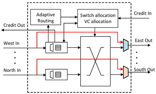
Figure 4.
Router micro-architecture overview with single-cycle intra-dimension bypass paths.
The bypass datapath is developed from the single-cycle-per-hop router DSR [11]. Packets traversing through the bypass datapath maintain their progress on the current dimension and incur a single-cycle delay. The adaptive datapath is similar to existing adaptive routers [15], but with a simplified VA scheme. We modify the VA to constrain a packet to retain its original VC. Moreover, VA is performed after SA in the same cycle non-speculatively. There is a single-bit tag in each flit to notify a downstream router if this flit can utilize the bypass datapath. If the tag bit is set, upon receiving the flit, a router will try to use the bypass datapath to transmit the flit; otherwise, the router lets it follow the adaptive routing datapath. Packets from all VCs have the chance to utilize the bypass datapath using the tagging mechanism proposed in this paper.
3.1. Intra-Dimension Bypassing
At very low loads, a packet can reach its destination through any of the minimal paths with similar latency. Inspired by this, we can pre-setup some crossbar connections that are potentially useful for some packets. Packets taking advantage of these paths can avoid crossbar setup and go directly to switch traversal. In this section, we first present the idea of bypassing and its bypass datapath, then we present how adding a dedicated VC for bypassing makes bypassing scalable and practical in a VC router.
3.1.1. Bypass Datapath
DSR [11] elegantly combines the routing algorithm with router micro-architecture optimization. We add a set of bypass paths on top of a VC router to achieve single-cycle intra-dimension traversal like that of DSR [11]. Figure 4 shows the overview of this adaptive router. During SA, if an output port receives no requests (indicating that the output port will be idle in next cycle), the output port is connected directly to the input channel of the opposite side in a router. For example, east output is connected to west input if it receives no requests from the buffered packets. In this case, an incoming packet of west input can go directly to the east output without waiting for switch allocation. We assume a 128-bit 1.5 mm-long bypass datapath (including crossbar and link). DSENT [48] reports that the bypass datapath can satisfy a delay constraint of 0.2 ns with proper repeater insertion. Traversing through a bypass path skips the buffering procedure, as well as multi-stage allocation procedures and incurs a single-cycle delay.
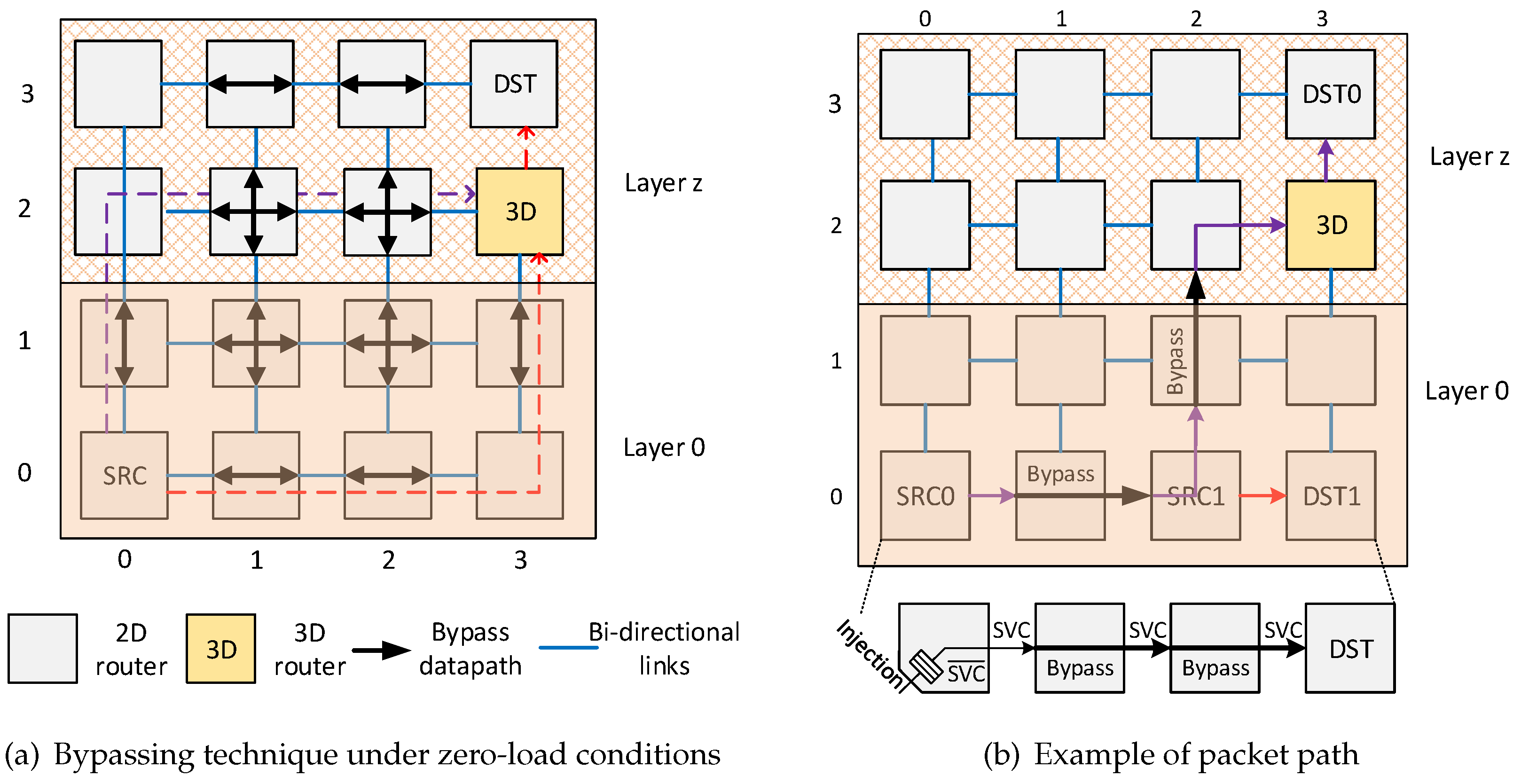
We use an example to demonstrate how these pre-setup datapaths can be utilized to transmit any packets. The thick arrows in Figure 5 represent the pre-setup bypass paths in a 4 × 4 × zinhomogeneous 3D mesh network under zero-load conditions. Suppose a packet is injected to router SRCand targets destination (DST) on layer z. At SRC, the router selects an output direction for the packet according to congestion status. If it chooses east output, the packet will go to Router (1,0,0) in the next hop. Router (1,0,0) has a bypass path from west to east. Hence, on Router (1,0,0), this packet can go to Router (2,0,0) directly without arbitration. The same procedure of bypassing works on Router (2,0,0), which sends the packet to Router (3,0,0). On Router (3,0,0), the packet needs to make a turn, is buffered and then sent to north output through the crossbar (in DSR [11], it is through a shared intermediate buffer). The south to north bypass path on Router (3,1,0) sends the packet to 3D Router (3,2,0) for interlayer traversal to the destination in layer z. The red dashed line shows the complete path for this packet if it selects east output at SRC, which is actually an XYZ routing path. Similarly, if north output is selected on SRC, the path of this packet will be the purple dashed line, which is a YXZ routing path.
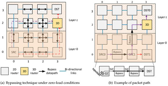
Figure 5.
Improved 2D router for inhomogeneous 3D NoCs.
The bypass datapath applies DoR on packets, so it utilizes the pre-setup intra-dimension crossbar connections. Utilizing these bypass paths skips the long adaptive routing pipeline and effectively reduces packet delay at low loads. Although the five-port 2D-mesh router is used in this paper, the idea of the pre-setup crossbar according to a certain routing algorithm can also be applied to other routers (e.g., homogeneous 3D-mesh routers).
3.1.2. Dedicated Virtual Channel for Bypassing
Our goal is to design an adaptive VC router with reduced low-load latency. Bypassing should be well designed to provide VC compatibility, meanwhile sustaining the efficiency of intra-dimension bypassing in DSR.
An incoming flit may belong to an arbitrary VC. Deciding whether a flit can bypass the current router, firstly the VC must be decoded, and then, the availability of corresponding credits for the downstream router must be checked. Here, we assume that the flit retains its VC ID when bypassing (VA details will be covered in Section 3.2.2). Suppose the VC ID of a received flit is vc, and the output port of DoR is o. If the following two conditions are met, the received flit can bypass the current router in one cycle. Firstly, bypassing must not cause overshooting to the destination (minimal routing). Secondly, the vc at output o must be idle (ensuring a successful VA). Implementing this bypassing logic requires using the VC ID as the input to index corresponding information. This control logic will inevitably increase the critical path length of bypassing logic compared to the one in [11] due to VC decoding. For example, the implementation on the X dimension is as follows:
bypassing <= (dst.x != current.x) &
      vc_idle[o][vc]
Preliminary synthesis result shows that the path delay for this decision-making on 16 VCs is 0.1 ns on the 45-nm standard cell library. In this implementation, the decision-making speed slows down as the number of VCs increases.
To speed up this process, we introduce a dedicated VC for bypassing. Suppose the special VC introduced is called the slide virtual channel (SVC). We now only perform bypassing for flits belonging to SVC. To check if an SVC flit can bypass the current router, a router only needs to check if the SVC of output o is idle. Bypass decision-making is faster because we do not need to use VC ID as the index to absorb credit information or other information. The processing speed is invariant to the number of VCs. If we use SVC for bypassing. The decision making on the X dimension is as follows:
if (svc) begin
 bypassing <= (dst.x != current.x) &
       svc_idle[o]
end
Path delay for this logic is reduced to 0.05 ns using the same 45-nm standard cell library.
Only SVC packets are considered for bypassing, and there is also dedicated buffer space reserved for SVC in each router. To avoid extra delays without the routers, the SVC buffer is restricted to only one slot. This design reduces the complexity of bypass decision-making. Bypassing with SVC is faster and, more importantly, invariant to the number of VCs. Adding an extra VC does not necessarily increase buffer space in the router because most NoC routers use a shared buffer between VCs [49].
3.1.3. SVC Tagging Mechanism
Packets of SVC can enjoy bypassing. Now, the problem is: what packet should be tagged with SVC? In this work, all VCs have the chance to be tagged with SVC to reduce overall packet delay and increase link utilization. SVC can be allocated to any packet that wins the output port. All packets are injected into the network with the SVC tag being zero. A router updates the SVC tag of a packet after it wins the output port. A packet has the first chance to be tagged with SVC when leaving its source. Each output port (excluding the ejection port) has a tagging unit. The principle to tag a head flit with SVC is simple, meeting the following two conditions:
- The SVC tag of the output port is not assigned to any packet.
- The SVC buffer at the corresponding downstream routeris empty.
Otherwise, the SVC tag bit is set to zero. The two rules work together as a lightweight SVC allocator, which assigns the SVC tag to packets. A body flit of a packet follows the SVC tag of its head flit, and the tail flit releases the possession of the SVC tag of that output port.
Figure 6 shows an example of SVC tagging. The SVC flag of this packet is initialized to zero () when it is injected to the network. Suppose the SVC tag of east output is idle, and the downstream SVC buffer is empty. When this packet wins the east output port, according to the SVC tagging rule above, its SVC flag will be set after SA. The downstream router that receives this packet will try to bypass this packet if possible. In this figure, the packet bypasses the second router because it is tagged with SVC in the first router. This example shows SVC tagging for the packet in the injection port. The SVC tagging works the same for all packets buffered in other input ports. As long as a packet can win an output port, it can be tagged with SVC if the two conditions for SVC tagging are met.

Figure 6.
An example of slide virtual channel (SVC) tagging. The packet is injected to the network with SVC being zero () and is tagged with when leaving its source node. Packets from other input buffers can be tagged with SVC, as well.
Considering the case where the proposed SVC mechanism is not employed, if the packet from the west port of the current router, as well as a packet from the injection port qualifies for the same bypass path, for instance, both packets must go through the VA to be assigned an appropriate VC on the output port as a bypass path. Therefore, if incoming packets to the bypass path belong to different VCs, the VC allocation per packet must be executed. This will incur extra overheads, which will slow down the bypassing decision-making. The proposed SVC and its tagging mechanism are a fast and scalable solution for single-cycle bypassing in virtual-channel adaptive routers. In this work, the SVC tagging is transparent to CPUs or upper level applications. Any packet that wins switch allocation on the current router has a chance to to be tagged with SVC. The packet tagged SVC can enjoy bypassing in the next hop.
3.2. Adaptive Routing
Packets that cannot utilize the bypass datapath are routed through the adaptive routing datapath in SlideAcross. We propose a cost-effective adaptive routing pipeline in SlideAcross, which is compatible with intra-dimension bypassing. We also propose a simple VA scheme to allow VA be performed efficiently after SA in the same cycle to reduce the adaptive routing pipeline. The network is also guaranteed to be deadlock-free based on the proposed VA scheme.
3.2.1. Router Pipeline
The adaptive router is mainly composed of the input buffer, crossbar and allocators. If a received packet cannot bypass the current router, it is written to the input buffer (BW), and meanwhile, route computation (RC) is performed. Adaptive selection is done automatically by masking the congested output port similar to [15]. The crossbar in this router is implemented using two sets of multiplexers like those in [17,50] to be cost effective. The SA process thus contains the arbitration for the multiplexer of the input buffer (SA-I) and that of the output port (SA-II). The winner of SA-II will then transmit a flit to the output link (LT). An idle VC of the output port is also assigned to the SA-II winner, which forms the VA procedure. Figure 7 shows the pipeline of this adaptive routing process. To support bypassing, upon receiving a packet, we need to perform bypassing control (BC) to determine if the packet should be written to the buffer, so there is a BC procedure before the BW operation in the pipeline. If the packet can bypass the current router, it follows the single-stage bypassing traversal (ST + LT).

Figure 7.
Bypassing and adaptive routing pipeline stages.
3.2.2. Virtual Channel Allocation
In SlideAcross, VA is performed non-speculatively after SA in the same cycle according to the pipeline design. VA is hence required to be very lightweight so as to prevent increasing the critical path delay of the router dramatically.
NoC uses VCs to implement the virtual network (VN) for CMP to isolate different types of messages. Each VN can also contain multiple VCs. In this work, we require at least two VCs (VC0 and VC1) in each VN to prevent routing deadlock. To make VA simple, we require a packet to retain its original VC inside its VN. For example, the packet of VC0 will still be VC0 after successful VA. Therefore, the VC of a packet is determined at injection and is not changed during its lifetime in the network. Such a simple VA rule can be appended to the SA process; the winner of an output port also owns the corresponding VC of the output port. The SVC tag (if idle) is also assigned to the winner of SA and performed in parallel with VA. This VA procedure is simpler than what has been done in [51], where VA picks up a VC from the idle VC pool and is done after SA in the same cycle. The high-performance router in [51] demonstrates the efficiency of such pipeline design.
Proposed VA scheme allows VA to be performed efficiently after SA in the same cycle, reducing the router pipeline without speculation. Due to this deterministic VC assignment scheme, a head flit requests for SA only when its VC at the output port is idle. Therefore, when a head flit wins SA, it will surely obtain a VC, increasing crossbar utilization. A potential drawback for this simple VA scheme is that the buffer utilization of different VCs can be imbalanced in asymmetric traffic patterns. However, this problem can also be solved by sharing the buffer between VCs [49].
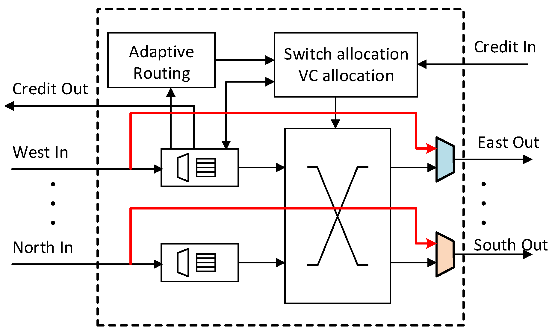
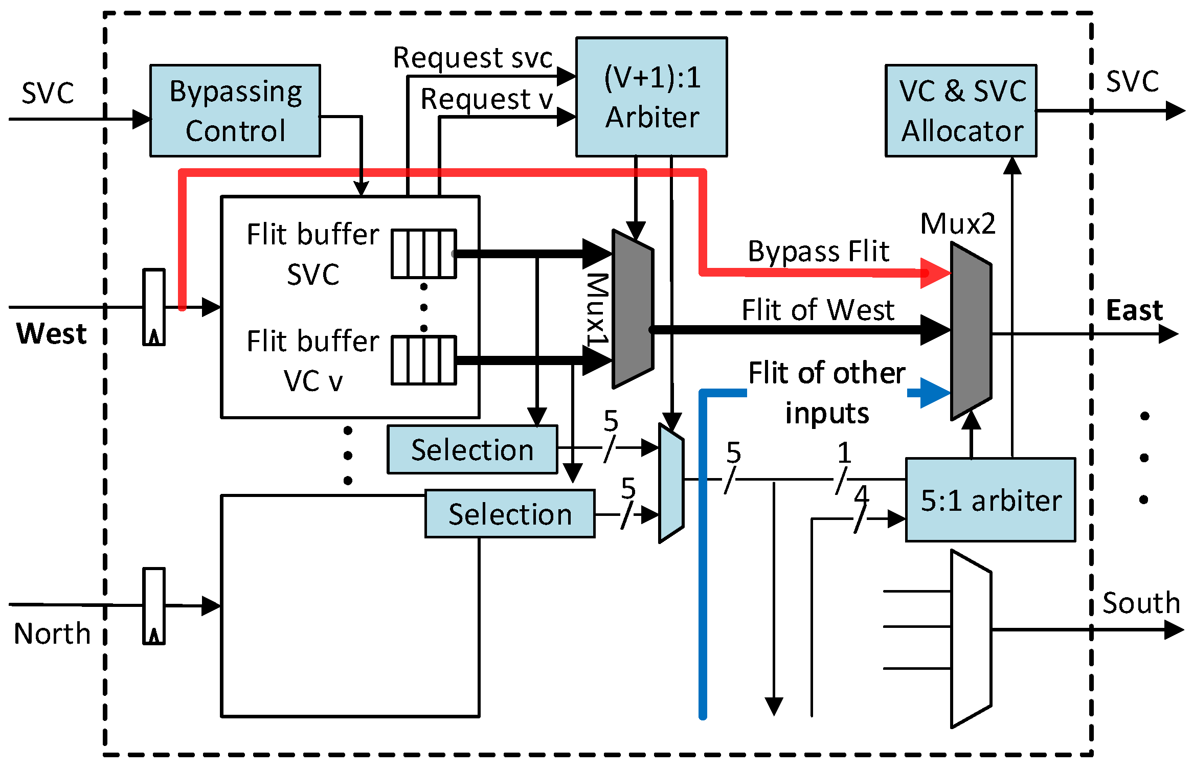
Figure 8 illustrates the adaptive routing datapath and the bypass datapath by detailing west input and east output. At each input port, there is an SVC buffer reserved for SVC packets. The crossbar is composed of input multiplexers and output multiplexers to be cost effective [17,50]. The red bold arrow in the figure is a bypass datapath that connects the west input link directly to the east output multiplexer. Mux2connects the red arrow with the east output port when there is no request for the east output port, forming one of the pre-setup intra-dimension bypass datapaths.
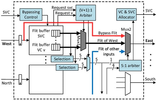
Figure 8.
Router micro-architecture.
Control modules are coloured with blue in this figure, including the bypassing control, input multiplexer arbiter, output multiplexer arbiter, VC allocator and SVC allocator. VC and SVC allocator absorb the arbitration results of the 5:1 arbiter (SA-II) and allocate the VC and SVC tag to the winning packet accordingly. Selection units automatically select the less congested path for buffered packets by masking the congested output port in the output port request vector.
3.2.3. Deadlock Avoidance
Routing in this router is minimal and fully adaptive and is hence prone to be deadlocked. To break the cycles in the resource dependency graph [52], we require at least two VCs (VC0 and VC1) in each VN. A packet is assigned to a VC during injection according to the position of its destination. Packets with a destination located at the left and right side of its source node are assigned to VC0 and VC1, respectively. If a packet’s destination is in the same column with the source node, the packet can be assigned to either VC randomly or according to congestion status. As the routing is minimal, turns in neither VC form a circle. Therefore, both VC0 and VC1 are deadlock-free.
Packets from all VCs have the chance to use the SVC buffer, so SVC can potentially be shared media that chain the turns of VC0 and VC1 to form a circle. To prevent this deadlock configuration, we only allow one packet to stay in the SVC buffer. This is achieved by controlling SVC tagging: a head flit will be tagged SVC only when the downstream SVC buffer is empty as imposed by the second rule in Section 3.1.3. Because SVC contains at most one packet, it will not chain up the turns of different VCs. The rules above all together guarantee a deadlock-free network. Sharing the SVC is also protocol-level deadlock-free. Suppose all SVCs are occupied by a certain class of message; messages of other classes can still reach their destination through the normal VCs, which are guaranteed to drain. Therefore, there will not be dependency between different classes of messages, making the network protocol-level deadlock-free.
4. Evaluation
We evaluate the performance of the proposed low-latency adaptive router using cycle-accurate simulator Noxim [53] and many-core simulator Sniper [9]. The baseline is a three-cycle (including LT) adaptive router [15]. We also include DSR [11] and the two-cycle router (including link traversal) SWIFT [19] for comparison. DSR has the lowest zero-delay among all routers due to its simple structure and functionality. However, DSR also requires credit throttling to prevent starvation. Baseline and SlideAcross are adaptive and use available buffer space as the congestion metric during path selection. SWIFT uses DoR and is source routed; a packet’s path is encoded in the lookahead control flit. Four routers are set to use the same amount of buffer to make a fair comparison. We use several synthetic traffic patterns to evaluate these NoCs. We also build the hop-by-hop simulated network model into Sniper to get the execution time of SPLASH-2 [8] workloads. We implement the router with Verilog HDL and report the area and power overhead using Synopsys Design Compiler with the 45-nm TSMCstandard cell library.
4.1. Bypassing Rate
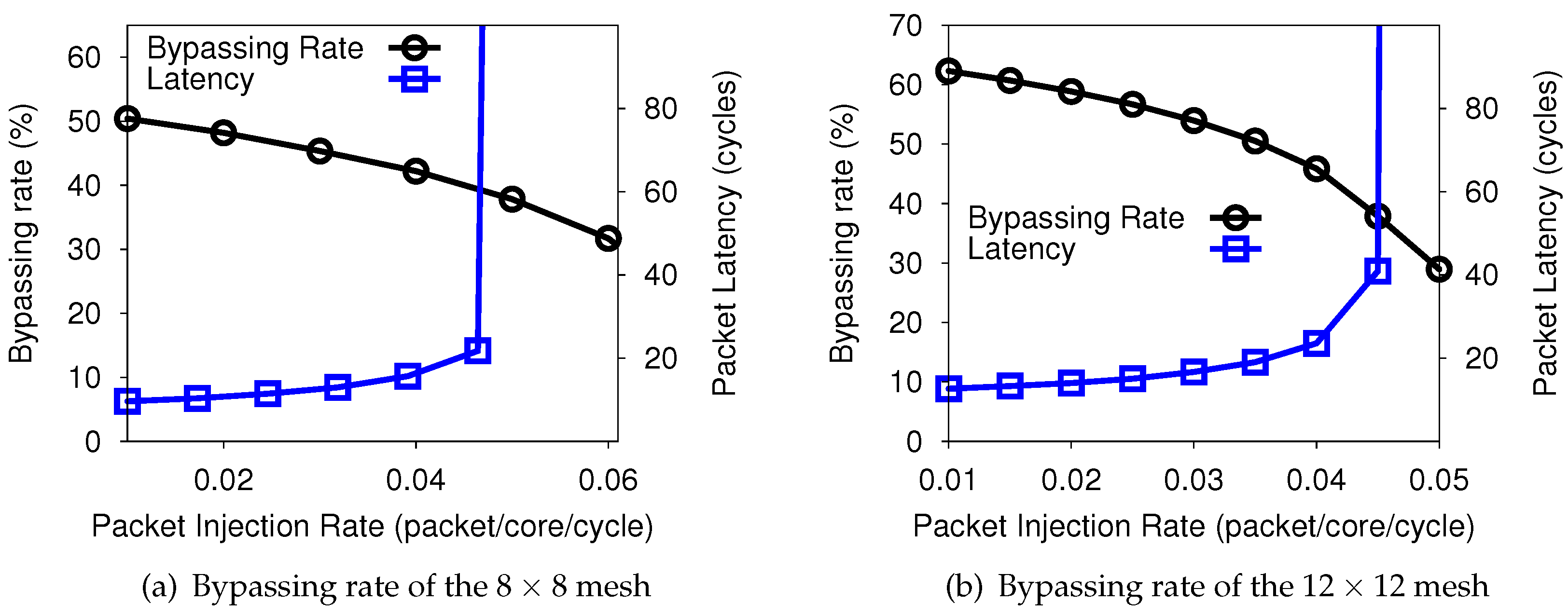
We examine how frequently these bypass paths can be utilized by packets. For each router, the bypassing rate is defined by the number of flits that benefit from the bypass datapath over the number of total received flits in the router. The network bypassing rate comes from averaging the bypassing rate of all routers. We collect the bypassing rate statistics under uniform random traffic of an mesh and mesh network. Figure 9 shows the bypassing rate of the and network over different packet injection rates. We also plot the average packet latency in the figures. Bypassing the rate decreases as the PIR increases, and network latency increases gradually before saturation. In the mesh, the zero-load bypassing rate (note: zero-load conditions could be used to model the bypass rate by employing the size of the mesh as parameters, which could be quantified (if a packet can be expected to “bypass” n routers and does not bypass m ones, its latency can be expressed as )) is 50.0%; in the network, the zero-load bypassing rate is 62.3%. As the network size increases, non-bypassing actions like dimension-switching and injection account for a smaller portion in the total path causing the bypassing rate to increase.
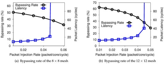
Figure 9.
Bypassing rate under random traffic.
4.2. Packet Delay of Synthetic Traffic
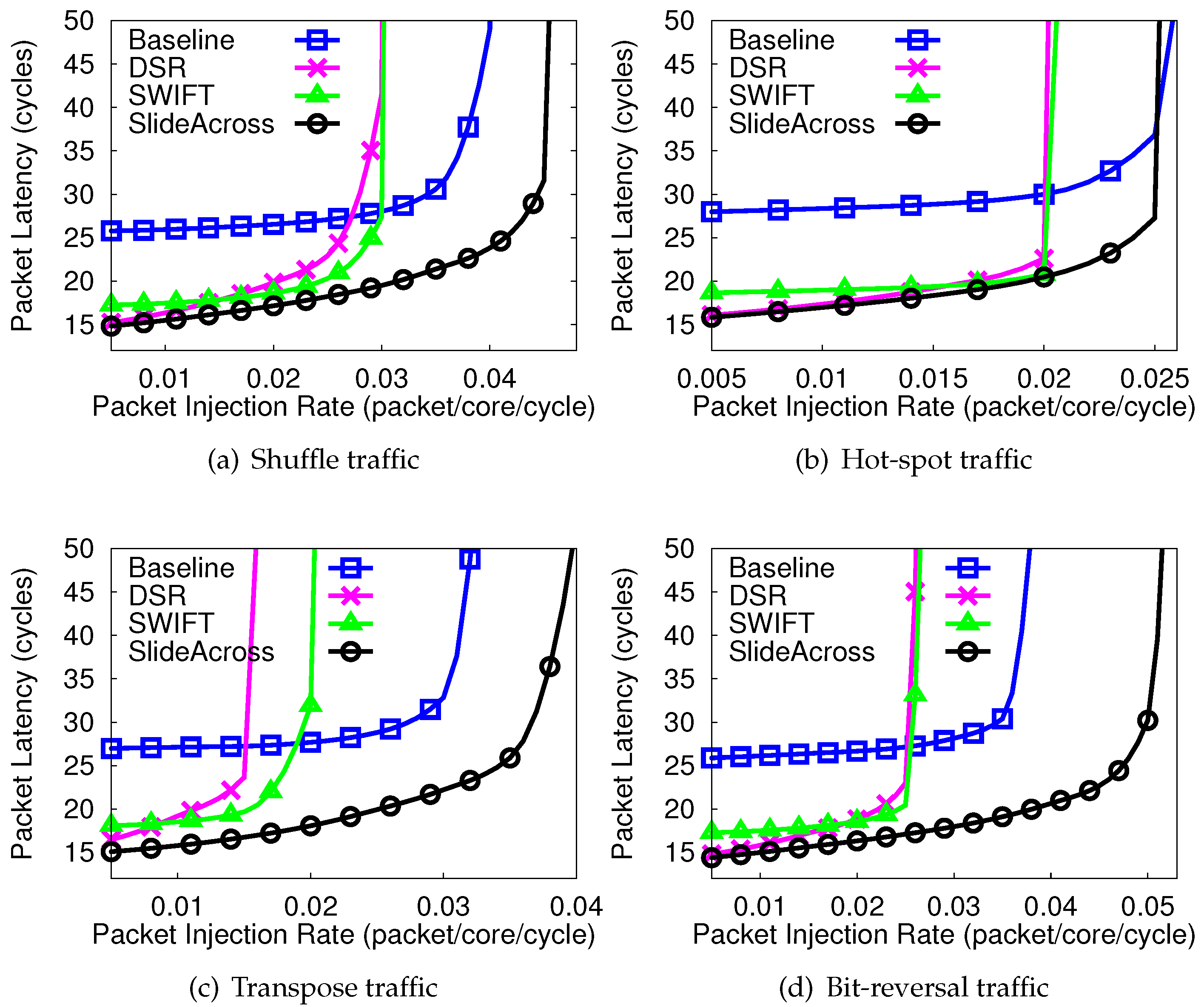
In this section, we present the packet latency results under various synthetic traffic patterns. We use four traffic patterns: shuffle, hot-spot, transpose and bit-reversal from Noxim [54]. Table 1 shows the basic setup of these simulations.

Table 1.
Simulation configuration for synthetic traffic.
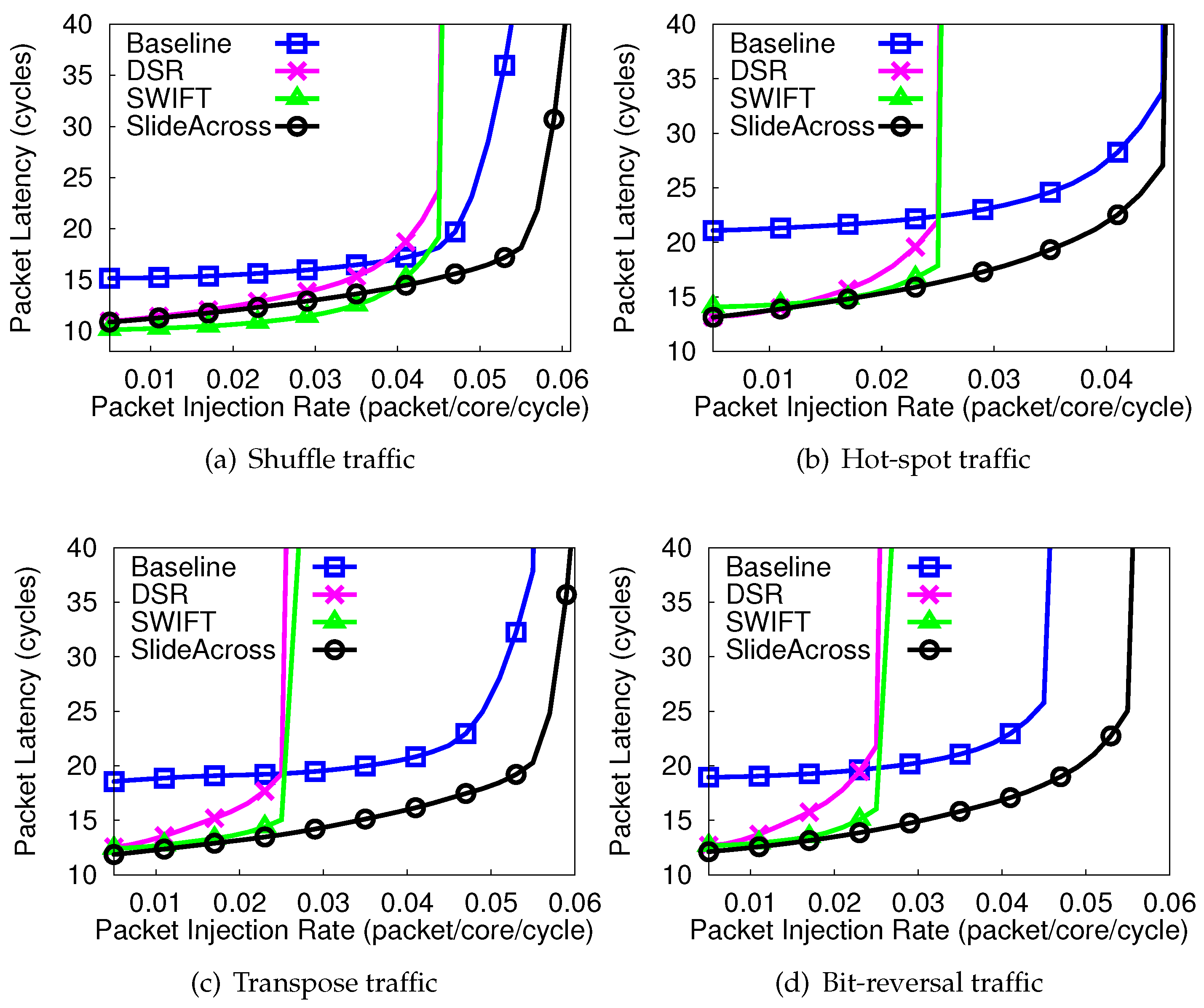
Figure 10 shows the average packet latency of an mesh network under four traffic patterns. In all four traffic patterns, at low injection rate (), SlideAcross and DSR have the lowest latency due to the lowest zero-load latency. In hot-spot, transpose and bit-reversal traffic, bypassing in SlideAcross works effectively, reducing packet delay by 6.2%, 9.8% and 13.1%, respectively, at , compared to SWIFT. In shuffle traffic, SWIFT has lower latency than SlideAcross when PIR is lower than 0.04. This is because the communication distance is usually short in shuffle traffic, and hence, the bypass channels in SlideAcross are not fully utilized.
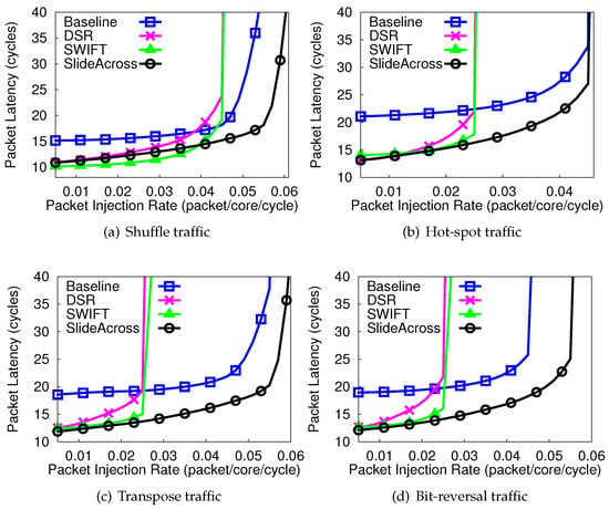
Figure 10.
Average packet latency in the mesh under four traffic patterns.
The adaptiveness of the network determines packet delay at high loads and the network’s saturation point. The saturation points of DSR and SWIFT are the same in all traffic patterns due to the same deterministic DoR routing algorithm employed. The baseline adaptive router, although, is slower at low PIR, but can achieve lower latency and higher throughput at high loads. SlideAcross achieves the largest network saturation point in the four synthetic traffic patterns evaluated. Although the same amount of buffer size and the same adaptive routing algorithm are employed, the saturation point of SlideAcross is 13.2%, 9.2% and 22.2% higher in shuffle, transpose and bit-reversal traffic than baseline. This demonstrates that intra-dimension bypassing does not only reduce low-load packet latency, but also improves the network’s maximal throughput.
Figure 11 shows the average packet latency of the mesh network. SlideAcross benefits from longer communication distance and has lower latency than SWIFT in all four traffic patterns under low loads. SlideAcross has an average reduction of 15.6% of the latency compared to SWIFT at due to the higher passing rate. Still adaptive routers (baseline and SlideAcross) achieve a higher network saturation point than DSR and SWIFT. SlideAcross also significantly improves the throughput of network in shuffle, transpose and bit-reversal traffic compared to SWIFT.
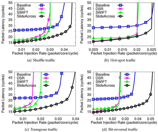
Figure 11.
Average packet latency in the mesh under four traffic patterns.
In summary, Figure 9, Figure 10 and Figure 11 reveal that the at low PIR, where the network is less congested, the bypass links are highly utilized to improve the packet latency of SlideAcross compared with SWIFT and DSR. Consequently, SlideAcross can sustain a higher saturation point as packets can move more freely in the NoC compared with existing architectures. It should be noted that if the NoC is configured with a larger packet size to buffer depth ratio, the saturation point will reduce in all cases due to high congestion probabilities. However, as shown in Figure 10 and Figure 11, SlideAcross has much lower average packet latency and can sustain more packets with a higher network saturation point compared to SWIFT and DSR. Specifically, under wormhole switching, flits in both SlideAcross and the baseline exploit the available buffer spaces to adaptively route packets in the network to their destinations with reduced latency. However, due to the effect of the bypass paths at low loads (although the bypass rate will be reduced), SlideAcross can still sustain load with a higher injection load compared with the baseline router.
4.3. Application Execution Time
We use Sniper [9] to simulate a 64-core high performance CMP that runs the SPLASH-2 [8] workloads. The configuration of this simulation is in Table 2. This configuration mimics a high-performance X86-64 processor with high memory bandwidth similar to the Intel Xeon Phi processor. We evaluate the application performance of baseline, SWIFT and the proposed SlideAcross network. DSR is not included, as it is not a virtual-channel router and may require multiple physical networks to isolate the traffic of different message classes.

Table 2.
Simulation setup for benchmarks.
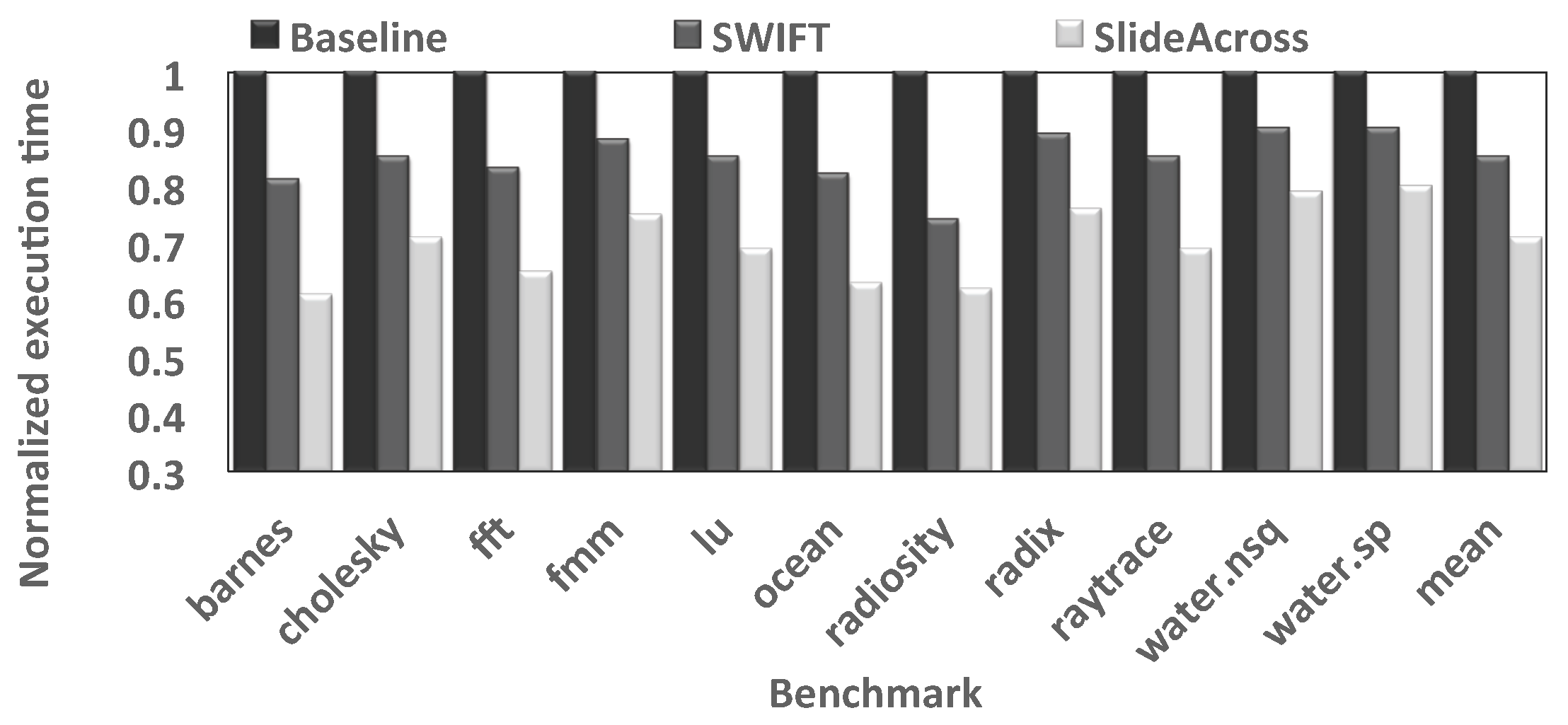
Figure 12 shows the execution time of SPLASH-2 workloads using different NoCs. The result is normalized to that of the baseline NoC. SlideAcross reduces applications’ execution time by an average of 29.2% and 16.9% compared to the baseline and SWIFT. For the low-injection rate application Barnes, SlideAcross reduces the execution time by 38.1%, showing the effectiveness of bypassing. The SPLASH-2 workloads have low average network utilization [18], so the performance under low-load conditions largely determines the system performance.
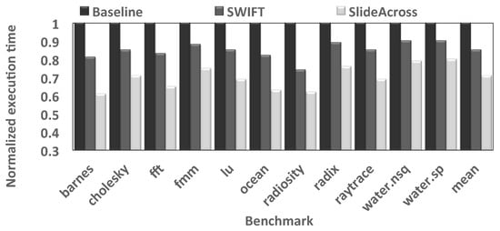
Figure 12.
Normalized execution time of SPLASH-2 workloads.
4.4. Area and Power Analysis
We implement the proposed router in RTLand synthesized it using Synopsys Design Compiler in TSMC 45-nm technology. This five-port router has 16 buffer slots in each input port, and the flit width is 128 bits. The operating frequency is set to be 2 GHz. We present the area and power of the adaptive router with and without the bypass datapath in Table 3. Bypassing increases the router’s area by 3.66% and power by 1.40%, mainly due to the larger crossbar used.

Table 3.
Area and power estimation.
We also examine the power overhead of sideband lookahead signals using DSENT [48]. In SWIFT, the flit width is 64-bit, and it requires a 14-bit lookahead flit for each data flit. Table 4 shows the link power differences with and without lookaheads at an injection rate of 0.1. The lookahead signals increase SWIFT’s link power consumption by 21.9%. SlideAcross can avoid such power overhead introduced by lookahead signals.

Table 4.
Lookahead signal overhead.
4.5. Impact of the Proposed Router on Inhomogeneous 3D NoCs
To evaluate the performance of the proposed bypassing technique in 3D NoCs, an extended version of (here, is employed to facilitate correlation with existing work on inhomogeneous 3D NoCs.), a cycle-accurate NoC simulator is used [3]. In the simulation, a fixed packet size of five flits is used. We employ a complex multimedia traffic (MMS) [55], Auto-indust and Telecom (from the E3S benchmark suite) [56] as the workload for our evaluation. The branch-and-bound [3] mapping algorithm algorithm is used to map the applications. The setup is run for a warm-up period of 2000 cycles and a simulation length of 200,000 simulation cycles. Hence, by introducing different delay models of 2D and 3D routers in the system, we have compared the average packet latency.
For inhomogeneous 3D NoCs with bypass techniques (also known as SlideAcross), we replace the conventional 2D routers by the SlideAcross routers. Hence, packets destined for other layers could be routed to the 3D router either via the bypass links or by the proposed deadlock-free adaptive routing to get access to the destination layer. Moreover, in the destination layer, packets can either exploit the bypass links or adaptive routing depending on the traffic conditions of the network, to the destination node. For a fair comparison, the performance-efficient buffer-nearest vertical hub (Buff NVH) [39] routing algorithm is employed for routing in existing inhomogeneous 3D NoCs. The Buff NVH routing algorithm always forwards packets towards the 3D node whose path provides the maximum output channel buffer space on the current core and has the closest Cartesian x,y to the current core, as well as the minimum Manhattan distance to the destination. We compare the proposed inhomogeneous 3D NoC with existing inhomogeneous 3D NoC architectures: Periphery, Chess, m column and half/lo. In Periphery, 3D routers are distributed along the peripherals of each layer, whereas in Chess, 3D and 2D routers are evenly distributed in each layer of the NoC by placing the 2D routers at least one hop away from a 3D router. In m column, 2D routers are placed along (n-m) number of columns in each layer with 2D routers placed on the same column number of every layer; where, n is the total number of columns in each layer and m can range between 1 and n−1. In half/lo, 2D routers placed as close to 3D routers as possible in each layer [2].
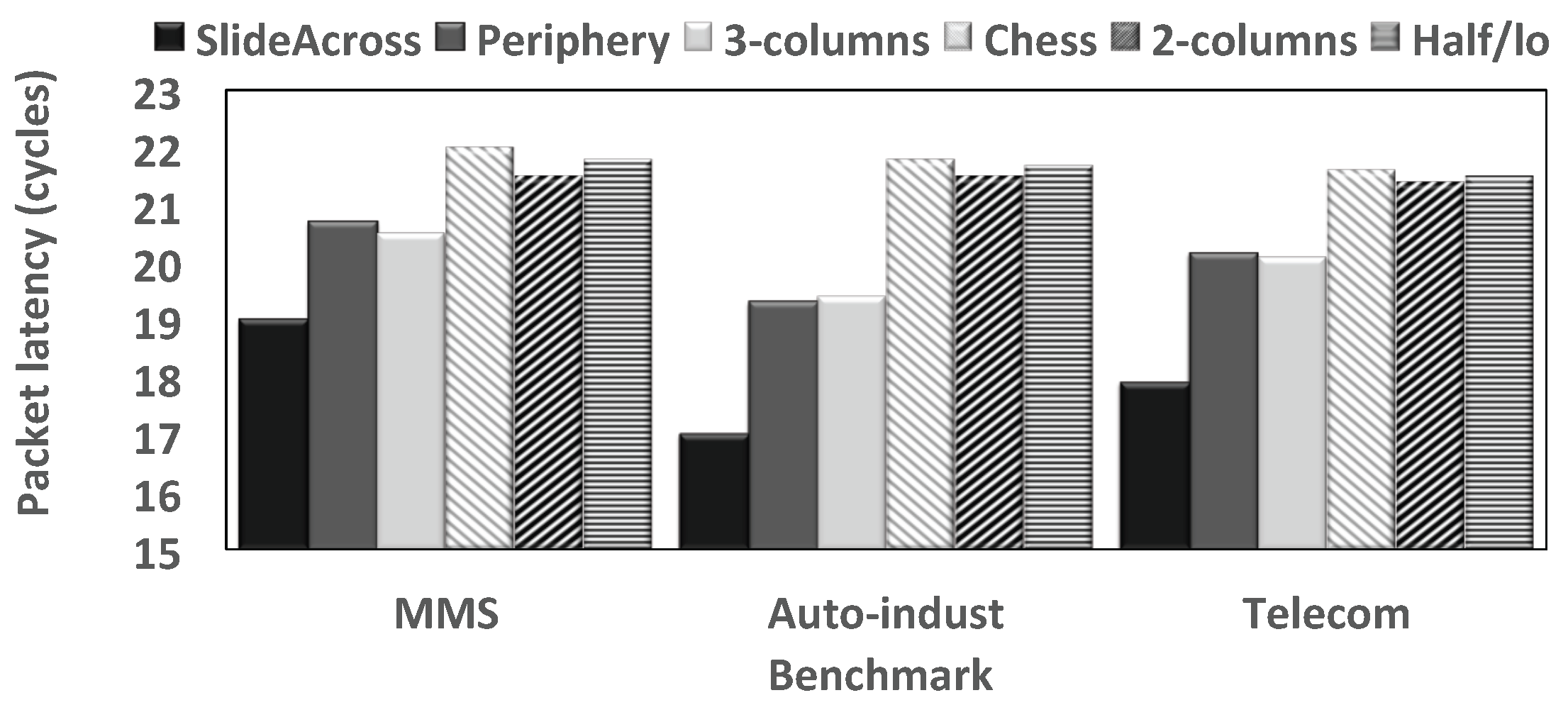
Figure 13 shows the average packet latency of various inhomogeneous architectures under different realistic benchmarks. By bypassing the links between 2D and 3D layers, SlideAcross has reduced average hop-count with less traffic loads within the layers and exploits the performance benefits of short vertical wires for inter-layer traversal. Hence, inhomogeneous 3D NoCs with SlidAcross have much lower packet latencies compared to existing inhomogeneous architectures. This is due to the extra delays introduced by the multi-hops between 2D routers and 3D routers, which reduce the performance of the NoC by increasing delays in the network, which consequently causes contention in conventional inhomogeneous 3D NoCs.
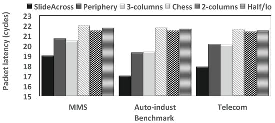
Figure 13.
Average packet latency of various inhomogeneous 3D NoCs.
4.6. Impact of the Proposed Router on WiNoCs
For an extensive validation of the performance benefits of the proposed router in emerging WiNoCs, the M5 simulator [57] is employed to acquire memory access traces from a full system running PARSEC v2.1 benchmarks [58], which is used to stimulate our version of the Noxim simulator. For correlation purposes, we have used the same setup as [47]. Hence, in the setup, 64 two-wide superscalar out-of-order cores with private 32 KB L1 instruction and data caches, as well as a shared 16 MB L2 cache are employed. Following the methodology presented in Netrace [59], the memory traces are post-processed to encode the dependencies between transactions. Consequently, the communication dependencies are enforced during the simulation. Memory accesses are interleaved at 4-KB page granularity among four on-chip memory controllers. A summary of the benchmarks is presented in Table 5. Thus, we apply a wide range of benchmarks with varied granularity and parallelism to study the effects of the proposed bypassing technique on the state-of-the-art wireless communication fabrics on WiNoCs. For each trace, we simulate at least 100 million cycles of the PARSEC-defined region of interest (ROI), where we schedule two threads per core. Five evenly-distributed nodes in the WiNoC are equipped with transceivers. All other nodes have receivers. For WiNoCs with bypass techniques, the receiving nodes are enhanced with SlideAcross routers. Similarly, for WiNoCs with SmallWorld, the receiving nodes are enhanced with the seven-port small world routers, which have long links with repeaters that connect directly to wireless nodes. Thus, packets can exploit both the bypass links and adaptive routing (Buff NVH) within the wireline layer to access the wireless and destination nodes. To model the effect of different bit-error-rates (BER) of the wireline and wireless layer on the network performance in terms of packet latency, we employ the packet error ratio (which dictates the probability of packet retransmission) [47]:
where is the packet length in bits and is the bit error probability, which is the expectation value of the BER for the communication fabric. Thus, Equation (1) is modelled and imported into the NoC simulator to assign the probability of retransmission of different communication fabrics at different packet injection rates. The alternating bit protocol is used for transmitting and receiving data and the credit flit (ACK/NACK). While wormhole flow control is used for the wireline layer, FDMAmedia access control is adopted to give more than one node the right to transmit over the shared wireless medium at a data rate of 256 Gbps in one clock cycle over 128 carrier frequencies. Fixed BERs of , and are used for mm-wave, wire and SW, respectively (Table 6).

Table 5.
Simulated PARSEC traces.

Table 6.
Simulation setup for Evaluating WiNoCs. SW, surface wave.
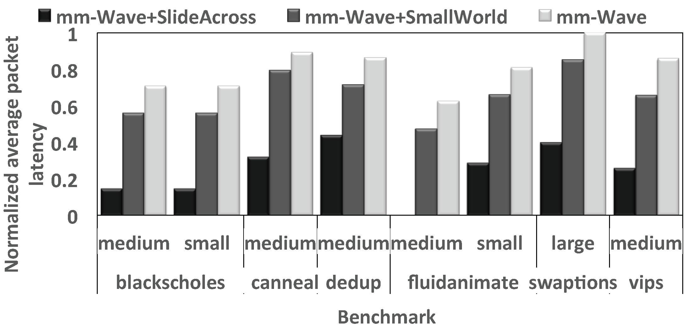
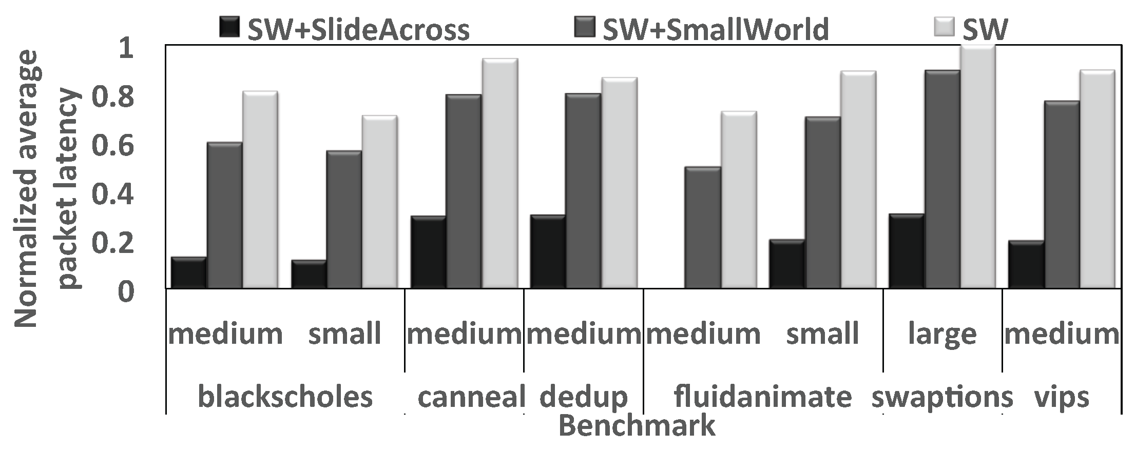
Figure 14 and Figure 15 show the normalized packet delays of various WiNoCs. Particularly, it can be deduced from Figure 14 that SlideAcross increases the performance of mm-wave significantly, compared to SmallWorld and conventional mm-wave WiNoCs. Besides having a larger crossbar with a seven-port router and longer input buffer waiting time, SmallWorld routing involves intermediate buffering, which increases the router pipeline and hence contention in the network. Consequently, packets in SlideAcross experience shorter delays in the reduced pipelined routers, which allow bypassing of the input buffers and crossbar.
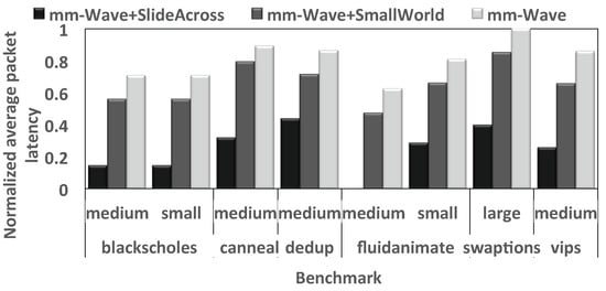
Figure 14.
Normalized average packet latency under the PARSEC benchmark.
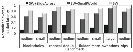
Figure 15.
Normalized average packet latency under the PARSEC benchmark.
Moreover, the performance improvement is more profound when these routers are employed in SW-enabled WiNoCs (Figure 15). This is expected as SW WiNoCs are less congested compared to mm-wave WiNoCs, as there are less retransmissions along the wireless channel. Consequently, the performance benefits of the bypass links in SlideAcross are more pronounced in SW than mm-wave. As shown in Figure 15, while SmallWorld can improve the performance of SW WiNoCs, SlideAcross significantly outperforms SmallWorld in all workloads. Furthermore, in high contention workloads, such as swaptions, where a large number of packets were simulated over a wide simulation cycle, SlideAcross achieves over performance improvement on average in both SW- and mm-wave enabled WiNoCs compared to SmallWorld.
5. Conclusions
In this paper, an efficient three-stage pipelined adaptive VC router with reduced low-load latency is proposed to improve the performance of emerging high performance communication fabric that promises to satisfy the communication dynamics of modern CMP design. The proposed router architecture has a cost-effective dual datapath design that can minimize packet delay under both low loads and high loads. A fast bypass datapath is proposed to alleviate the performance degradation due to multi-hops along the long horizontal wires of the state-of-the art hybrid NoC architectures under low-load conditions. Furthermore, a deadlock-free adaptive routing algorithm is proposed to avoid congested paths when the NoC is heavily loaded with traffic. Emerging high-performance and low-cost NoC architectures, such as inhomogeneous 3D NoCs, mm-wave- and surface wave-based hybrid wired-wireless NoCs, suffer from reduced performance due to the heterogeneity in hop count and wire delays between the present communication fabric. Thus, the proposed dual datapath router is designed to extend the performance of the 2D routers in such hybrid NoC. Cycle-accurate experiments show that the proposed router can significantly reduce applications’ execution time (e.g., by an average of 16.9% compared to the low-latency router SWIFT). Furthermore, the performance effect of replacing conventional 2D routers with the proposed router architecture in inhomogeneous 3D NoC,s as well as mm-wave and surface wave hybrid wired-wireless NoCs is evaluated by cycle-accurate simulations. The experimental results show significant reductions in the average packet delay compared to existing high-performance inhomogeneous 3D NoCs and SmallWorld-enabled hybrid wired-wireless NoCs, even when efficient adaptive routing is used. Future work includes a reliability model for the proposed 2D router to address the TSV yield and failure issues in 3D NoCs, as well as the QoS-aware run-time adaptive routing algorithm and NoC architecture for optimized communication in WiNoCs.
Author Contributions
Michael Opoku Agyeman and Wen Zong conceived and designed the experiments; Wen Zong proposed, implemented the router architecture and perform experiments on them; Michael Opoku Agyeman extended the router architecture to hybrid 3D and Wireless NoCs; Alex Yakovlev, Kin-Fai Tong and Terrence Mak analysed the data, contributed to the formulation of Surface-Wave WiNoC theories and experimental setup; Michael Opoku Agyeman and Wen Zong wrote the paper.
Conflicts of Interest
The authors declare no conflict of interest.
References
- Siozios, K.; Bartzas, A.; Soudris, D. Three Dimensional Network-on-Chip Architectures. In Networks-on-Chips: Theory and Practice; Fayez Gebali, H.E., El-Kharashi, M.W., Eds.; CRC Press: Boca Raton, FL, USA, 2009; pp. 1–28. [Google Scholar]
- Agyeman, M.O.; Ahmadinia, A.; Shahrabi, A. Heterogeneous 3D network-on-chip architectures: Area and power aware design techniques. J. Circuits Syst. Comput. 2013, 22, 1350016. [Google Scholar] [CrossRef]
- Agyeman, M.O.; Ahmadinia, A.; Bagherzadeh, N. Performance and Energy Aware Inhomogeneous 3D Networks-on-Chip Architecture Generation. IEEE Trans. Parallel Distrib. Syst. 2015, 27, 1756–1769. [Google Scholar] [CrossRef]
- Matsutani, H.; Bogdan, P.; Marculescu, R.; Take, Y.; Sasaki, D.; Zhang, H.; Koibuchi, M.; Kuroda, T.; Amano, H. A case for wireless 3D NoCs for CMPs. In Proceedings of the 2013 18th Asia and south Pacific Design Automation Conference (ASP-DAC), Yokohama, Japan, 22–25 January 2013; pp. 23–28. [Google Scholar]
- Agyeman, M.O. A Study of Optimization Techniques for 3D Networks-on-Chip Architectures for Low Power and High Performance Applications. Int. J. Comput. Appl. 2015, 121, 1–8. [Google Scholar]
- Agyeman, M.O.; Wan, J.X.; Vien, Q.T.; Zong, W.; Yakovlev, A.; Tong, K.; Mak, T. On the Design of Reliable Hybrid Wired-Wireless Network-on-Chip Architectures. In Proceedings of the IEEE Embedded Multicore/Many-Core Systems-on-Chip (MCSoC), Turin, Italy, 23–25 September 2015; pp. 251–258. [Google Scholar]
- Heirman, W.; Dambre, J.; Stroobandt, D.; Van Campenhout, J. Rent’s rule and parallel programs: Characterizing network traffic behavior. In Proceedings of the 2008 International Workshop on System Level Interconnect Prediction (SLIP), Newcastle, UK, 5–6 April 2008; pp. 87–94. [Google Scholar]
- Woo, S.C.; Ohara, M.; Torrie, E.; Singh, J.P.; Gupta, A. The SPLASH-2 programs: Characterization and methodological considerations. In Proceedings of the 22nd Annual International Symposium on Computer Architecture (ISCA), S. Margherita Ligure, Italy, 22–24 June 1995; Volume 23, pp. 24–36. [Google Scholar]
- Carlson, T.E.; Heirman, W.; Eeckhout, L. Sniper: Exploring the level of abstraction for scalable and accurate parallel multi-core simulation. In Proceedings of the 2011 International Conference for High Performance Computing, Networking, Storage and Analysis (SC’11), Seattle, WA, USA, 12 November 2011; p. 52. [Google Scholar]
- Duato, J. A new theory of deadlock-free adaptive routing in wormhole networks. TPDS 1993, 4, 1320–1331. [Google Scholar]
- Kim, J. Low-cost router microarchitecture for on-chip networks. In Proceedings of the Microarchitecture (MICRO), New York, NY, USA, 12–16 December 2009; pp. 255–266. [Google Scholar]
- Ausavarungnirun, R.; Fallin, C.; Yu, X.; Chang, K.K.W.; Nazario, G.; Das, R.; Loh, G.H.; Mutlu, O. Design and evaluation of hierarchical rings with deflection routing. In Proceedings of the IEEE 26th International Symposium on Computer Architecture and High Performance Computing (SBAC-PAD), Paris, France, 22–24 October 2014; pp. 230–237. [Google Scholar]
- Jerger, N.E.; Peh, L.S. On-Chip Networks. Morgan and Claypool Publishers: San Rafael, CA, USA, 2009; pp. 1–141. [Google Scholar]
- Owens, J.D.; Dally, W.J.; Ho, R.; Jayasimha, D.N.; Keckler, S.W.; Peh, L.S. Research Challenges for On-Chip Interconnection Networks. IEEE Micro 2007, 27, 96–108. [Google Scholar] [CrossRef]
- Kim, J.; Park, D.; Theocharides, T.; Vijaykrishnan, N.; Das, C.R. A low latency router supporting adaptivity for on-chip interconnects. In Proceedings of the DAC, Shanghai, China, 18–21 January 2005; pp. 559–564. [Google Scholar]
- Gratz, P.; Grot, B.; Keckler, S.W. Regional congestion awareness for load balance in networks-on-chip. In Proceedings of the IEEE 14th International Symposium on High Performance Computer Architecture (HPCA), Salt Lake City, UT, USA, 16–20 Febuary 2008; pp. 203–214. [Google Scholar]
- Peh, L.S.; Dally, W.J. A delay model and speculative architecture for pipelined routers. In Proceedings of the IEEE 14th International Symposium on High Performance Computer Architecture (HPCA), Monterrey, Nuevo Leon, Mexico, 20–24 January 2001; pp. 255–266. [Google Scholar]
- He, Y.; Sasaki, H.; Miwa, S.; Nakamura, H. McRouter: Multicast within a router for high performance network-on-chips. Proceedings of 12th International Conference on Parallel Computing Technologies (PaCT-2013), Edinburgh, Scotland, UK, 7–11 October 2013; pp. 319–330. [Google Scholar]
- Krishna, T.; Postman, J.; Edmonds, C.; Peh, L.S.; Chiang, P. Swift: A swing-reduced interconnect for a token-based network-on-chip in 90 nm cmos. In Proceedings of the 2010 IEEE International Conference on Computer Design (ICCD 2010), Amsterdam, The Netherlands, 3–6 October 2010; pp. 439–446. [Google Scholar]
- Chen, C.H.O.; Park, S.; Krishna, T.; Subramanian, S.; Chandrakasan, A.P.; Peh, L.S. SMART: A single-cycle reconfigurable NoC for SoC applications. In Proceedings of the Design Automation and Test in Europe (DATE), Grenoble, France, 18–22 March 2013; pp. 338–343. [Google Scholar]
- Jain, T.N.; Gratz, P.V.; Sprintson, A.; Choi, G. Asynchronous bypass channels: Improving performance for multi-synchronous nocs. In Proceedings of the Networks-on-Chip (NOCS), Grenoble, France, 3–6 May 2010; pp. 51–58. [Google Scholar]
- Krishna, T.; Chen, C.H.O.; Kwon, W.C.; Peh, L.S. Breaking the on-chip latency barrier using SMART. In Proceedings of the High Performance Computer Architecture (HPCA), Shenzhen, China, 23–27 February 2013; pp. 378–389. [Google Scholar]
- Kumar, R.; Yang, Y.S.; Choi, G. Intra-flit skew reduction for asynchronous bypass channel in nocs. In Proceedings of the VLSI Design, Chennai, India, 2–7 January 2011; pp. 238–243. [Google Scholar]
- Park, S.; Krishna, T.; Chen, C.H.; Daya, B.; Chandrakasan, A.; Peh, L.S. Approaching the theoretical limits of a mesh NoC with a 16-node chip prototype in 45 nm SOI. In Proceedings of the Design Automation Conference (DAC 2012), San Francisco, CA, USA, 3–7 June 2012; pp. 398–405. [Google Scholar]
- Kim, J.; Balfour, J.; Dally, W. Flattened butterfly topology for on-chip networks. In Proceedings of the Microarchitecture (MICRO), Chicago, IL, USA, 1–5 December 2007; IEEE Computer Society: Washington, DC, USA; pp. 172–182. [Google Scholar]
- Grot, B.; Hestness, J.; Keckler, S.W.; Mutlu, O. Express cube topologies for on-chip interconnects. In Proceedings of the High Performance Computer Architecture (HPCA), Raleigh, NC, USA, 14–18 February 2009; pp. 163–174. [Google Scholar]
- Vivet, P.; Thonnart, Y.; Lemaire, R.; Beigne, E.; Bernard, C.; Darve, F.; Lattard, D.; Miro-Panades, I.; Santos, C.; Clermidy, F.; et al. 8.1 A 4 × 4 × 2 homogeneous scalable 3D network-on-chip circuit with 326MFlit/s 0.66pJ/b robust and fault-tolerant asynchronous 3D links. In Proceedings of the IEEE International Solid-State Circuits Conference (ISSCC), San Francisco, CA, USA, 21 February 2016; pp. 146–147. [Google Scholar]
- Carloni, L.P.; Pande, P.; Xie, Y. Networks-on-chip in emerging interconnect paradigms: Advantages and challenges. In Proceedings of the ACM/IEEE International Symposium on Networks-on-Chip (NOCS), San Diego, CA, USA, 10–13 May 2009; pp. 93–102. [Google Scholar]
- Kim, J.; Nicopoulos, C.; Park, D.; Das, R.; Xie, Y.; Narayanan, V.; Yousif, M.S.; Das, C.R. A novel dimensionally-decomposed router for on-chip communication in 3D architectures. SIGARCH Comput. Archit. News 2007, 35, 138–149. [Google Scholar] [CrossRef]
- Li, F.; Nicopoulos, C.; Richardson, T.; Xie, Y.; Narayanan, V.; Kandemir, M. Design and Management of 3D Chip Multiprocessors Using Network-in-Memory. In Proceedings of the International Symposium on Computer Architecture (ISCA), Boston, MA, USA, 17–21 June 2006; pp. 130–141. [Google Scholar]
- Xie, Y.; Cong, J.; Sapatneker, S. System-Level 3D IC Cost Analysis and Design Exploration. In Three Dimensional Integrated Circuit Design; Springer: New York City, USA, 2010; pp. 261–280. [Google Scholar]
- Xu, T.; Liljeberg, P.; Tenhunen, H. A study of Through Silicon via impact to 3D Network-on-Chip design. In Proceedings of the 2010 International Conference on Electronics and Information Engineering (ICEIE), Kyoto, Japan, 1–3 August 2010; pp. 333–337. [Google Scholar]
- Liu, C.; Zhang, L.; Han, Y.; Li, X. Vertical interconnects squeezing in symmetric 3D mesh Network-on-Chip. In Proceedings of the Asia and south Pacific Design Automation Conference (ASP-DAC), Yokohama, Japan, 25–28 January 2011; pp. 357–362. [Google Scholar]
- Wang, Y.; He, Y.-N.; Zhang, L.; Fu, B.Z.; Liu, C.; Li, H.-W.; Li, X. Economizing TSV Resources in 3D Network-on-Chip Design. IEEE Trans. Very Large Scale Integr. (VLSI) Syst. 2014, 23, 493–506. [Google Scholar] [CrossRef]
- Pasricha, S. Exploring serial vertical interconnects for 3D ICs. In Proceedings of the Design Automation Conference (DAC), San Francisco, CA, USA, 26–31 July 2009; pp. 581–586. [Google Scholar]
- Pasricha, S. A Framework for TSV Serialization-aware Synthesis of Application Specific 3D Networks-on-Chip. Proceesings of the International Conference on VLSI Design (VLSID), Honolulu, HI, USA, 13 June 2012; pp. 268–273. [Google Scholar]
- Xu, T.C.; Schley, G.; Liljeberg, P.; Radetzki, M.; Plosila, J.; Tenhunen, H. Optimal placement of vertical connections in 3D Network-on-Chip. J. Syst. Archit. 2013, 59, 441–454. [Google Scholar] [CrossRef]
- Miller, F.; Wild, T.; Herkersdorf, A. TSV-virtualization for Multi-protocol-Interconnect in 3D-ICs. Proceesings of the Euromicro Conference on Digital System Design (DSD), Cesme, Izmir, Turkey, 5–8 September 2012; pp. 374–381. [Google Scholar]
- Agyeman, M.O.; Ahmadinia, A.; Shahrabi, A. Efficient Routing Techniques in Heterogeneous 3D Networks-on-Chip. Parallel Comput. 2013, 39, 389–407. [Google Scholar] [CrossRef]
- Bose, A.; Ghosal, P.; Mohanty, S.P. A Low Latency Scalable 3D NoC Using BFT Topology with Table Based Uniform Routing. In Proceedings of the IEEE Computer Society Annual Symposium on VLSI (ISVLSI), Tampa, FL, USA, 9–11 July 2014; pp. 136–141. [Google Scholar]
- Rose, A.; Ramachandran, S.R. Genetic Algorithm Based Optimization of Vertical Links for Efficient 3D NoC Multicore Crypto Processor. Int. Symp. Qual. Electron. Des. 2013, 8, 1082–1090. [Google Scholar]
- Bahmani, M.; Sheibanyrad, A.; Petrot, F.; Dubois, F.; Durante, P. A 3D-NoC Router Implementation Exploiting Vertically-Partially-Connected Topologies. Proceesings of the IEEE Computer Society Annual Symposium on VLSI (ISVLSI), Amherst, MA, USA, 19–21 August 2012; pp. 9–14. [Google Scholar]
- OpokuAgyeman, M. 3D Networks-on-Chip Architecture Optimization for Low Power Design; LAP LAMBERT Academic Publishing: Saarbrücken, Germany, 2015. [Google Scholar]
- Agyeman, M.O.; Ahmadinia, A. Optimised Application Specific Architecture Generation and Mapping Approach for Heterogeneous 3D Networks-on-Chip. Proceesings of the IEEE International Conference on Computational Science and Engineering, Sydney, Australia, 3–5 December 2013; pp. 794–801. [Google Scholar]
- Yu, X.; Sah, S.; Deb, S.; Pande, P.; Belzer, B.; Heo, D. A wideband body-enabled millimetre-wave transceiver for wireless Network-on-Chip. Proceesings of the Midwest Symposium on Circuits and Systems (MWSCAS), Seoul, Korea, 7–10 August 2011; pp. 1–4. [Google Scholar]
- Xiao, C.; Huang, Z.; Li, D. A Tutorial for Key Problems in the Design of Hybrid Hierarchical NoC Architectures with Wireless/RF. Smart CR 2013, 3, 425–436. [Google Scholar] [CrossRef]
- Agyeman, M.O.; Vien, Q.T.; Ahmadnia, A.; Yakovlev, A.; Tong, K.F.; Mak, T. A Resilient 2-D Waveguide Communication Fabric for Hybrid Wired-Wireless NoC Design. IEEE Trans. Parallel Distrib. Syst. 2016, 28, 359–373. [Google Scholar]
- Sun, C.; Sun, C.; Chen, C.H.O.; Kurian, G.; Wei, L.; Miller, J.; Agarwal, A.; Peh, L.S.; Stojanovic, V. DSENT-a tool connecting emerging photonics with electronics for opto-electronic networks- on-chip modeling. In Proceedings of the NOCS, Copenhagen, Denmark, 9–11 May 2012; pp. 201–210. [Google Scholar]
- Becker, D.U. Efficient Microarchitecture for Network-on-Chip Routers. Ph.D. Thesis, Stanford University, Stanford, CA, USA, 2012. [Google Scholar]
- Mullins, R.; west, A.; Moore, S. Low-latency virtual-channel routers for on-chip networks. In Proceedings of the International Symposium on Computer Architecture (ISCA), Munich, Germany, 19–23 June 2004; Volume 32, p. 188. [Google Scholar]
- Kumar, A.; Kunduz, P.; Singhx, A.P.; Pehy, L.S.; Jhay, N.K. A 4.6 Tbits/s 3.6 GHz single-cycle NoC router with a novel switch allocator in 65 nm CMOS. In Proceedings of the International Conference on Computer Design (ICCD), Lake Tahoe, CA, USA, 7–10 October 2007; pp. 63–70. [Google Scholar]
- Dally, W.; Towles, B. Principles and Practices of Interconnection Networks; Morgan Kaufmann Publishers Inc.: San Francisco, CA, USA, 2003. [Google Scholar]
- Catania, V.; Mineo, A.; Monteleone, S.; Palesi, M.; Patti, D. Cycle-Accurate Network on Chip Simulation with Noxim. ACM Trans. Model. Comput. Simul. 2016, 27, 1–25. [Google Scholar] [CrossRef]
- Fazzino, F.; Palesi, M.; Patti, D. Noxim: Network-on-Chip Simulator. Available online: http://sourceforge.net/projects/noxim (accessed on 31 December 2008).
- Hu, J.; Marculescu, R. Energy- and performance-aware mapping for regular NoC architectures. IEEE Trans. Comput.-Aided Des. Integr. Circuits Syst. 2005, 24, 551–562. [Google Scholar]
- Dick, R. Embedded System Synthesis Benchmarks Suite (E3S). Available online: ziyang.eecs.umich.edu/dickrp/e3s (accessed on 25 April 2017).
- Binkert, N.; Dreslinski, R.; Hsu, L.; Lim, K.; Saidi, A.; Reinhardt, S. The M5 Simulator: Modeling Networked Systems. IEEE Micro 2006, 26, 52–60. [Google Scholar] [CrossRef]
- Bienia, C.; Kumar, S.; Singh, J.P.; Li, K. The PARSEC Benchmark Suite: Characterization and Architectural Implications. In Proceedings of the Parallel Architectures and Compilation Techniques, Toronto, ON, Canada, 25–29 October 2008; pp. 72–81. [Google Scholar]
- Hestness, J.; Grot, B.; Keckler, S.W. Netrace: Dependency-driven Trace-based Network-on-chip Simulation. In Proceedings of the 3rd International Workshop on Network on Chip Architectures (NoCArc 2010), Atlanta, GA, USA, 4–8 December 2010; pp. 31–36. [Google Scholar]
© 2017 by the authors. Licensee MDPI, Basel, Switzerland. This article is an open access article distributed under the terms and conditions of the Creative Commons Attribution (CC BY) license (http://creativecommons.org/licenses/by/4.0/).

