Abstract
One of the major power consuming components in a computer is its display unit. On average the screen consumes ten times more power than the DSP processor itself. Thus, reducing the power consumption should be one of the most important tasks in the development of low power consumption computing systems. In this paper we present one possible solution involving micro projection device based upon lasers and a digital light processing (DLP) matrix which is a matrix of electrically controllable mirrors capable of translating electrical signal to a time varying projected image. It can serve to substitute a screen and consume ten times less power than a conventional screen. The described device is a multifunctional highly efficient customized DLP light engine being capable of serving as an image projector and simultaneously to support range and topography estimation measurements.
1. Introduction
The low power consuming micro projector could be a very useful device for a wide set of applications such as a virtual screen of cellular phones or portable computers. The most common technique for projection uses illumination lamps, spatial light modulators and imaging lenses. Those devices consume more than 300 W as they are highly inefficient. Other techniques such as digital paper or direct retinal projection have either technological drawbacks or disadvantages in price and operation time in comparison to the technique described in this paper.
According to the article published at GRASP Symposium at Wichita State University, 2010 the display consumes 25% of the energy in today’s typical lap-tops. Their test showed an average of 19 W. Since display also consumes significant space and size, a substitute which could cut down size weight and power consumption while yet maintaining the capability in producing a large display, is definitely an appealing technological direction having a growing interest of large consumer electronics manufacturers worldwide.
In this paper we aim to demonstrate a combination of several new and emerging techniques in virtual displays, while some of which have been demonstrated separately but so far they were never integrated together into a single projecting module resulting in a more efficient engine (compared e.g., even to an LCD based display).
Note that the directional projection approaches such as head mounted or direct retinal displays do not allow sharing the displayed information with other participants [1,2,3,4,5]. While in our case the suggested low energy consuming projector is based on a spatially coherent polarized diode laser and a set of spatial optical data processing elements (such as an improved spatial light modulator (SLM) that is based upon a digital light processor (DLP)) that are designed to increase the energetic efficiency. The combination of all those aspects allows the realization of this portable projector, despite of failures obtained in similar attempts in the past [6,7,8,9,10]. The suggested portable projector is good for both private as well as for screen sharing applications. Whereas the authors previously attempted to construct a laser based micro projection that lacked sufficient high performance [11,12,13], the modifications in the current demonstrator suggest a very appealing outcome with regard to overall performance.
In this paper we briefly present the design, construction and preliminary characterization of a micro projector providing output colored images. This micro projector consumes an average power of less than 3 W while delivering 10 lumens of brightness to a substitute of a 12" screen.
2. Technological Description
The main goal demonstrated in this paper relates to the preliminary realization of an integrated and multi-functional DLP based pico projector. We believe that these multi-functional capabilities are going to be integrated in many future developed projection devices. Thus, let us first start by describing the main difference between the DLP based multi-functional projector that is being presented in this paper, and other existing micro/pico projection techniques.
In recent years, there have been significant changes in the integration of projection engines for new applications. A trend of implementing these light engines is evolving in commercial and industrial applications. The popular growing application is micro/pico projection which is a miniature video projector that can project large image displays out of small devices such as portable light weight electronic devices. Efficiency in an essential feature in mobile electronics especially due to the need to reduce the dimensions and the obtainable heat dissipation while, in parallel, maximizing the operating time of small sized batteries.
The Digital Micro-mirror Device (DMD) is a miniature component that can modulate light while maintaining high optical and electrical efficiency. This makes this technology an attractive solution in mobile devices. For example, a DMD from DLP1700 mini series (0.17", 0.3") is a miniaturized version designed by TI (Texas Instruments) for the pico projection market. The reflectivity of the mirrors is approximately 90% and they consist of a fill factor of 92%. The electrical energy consumption of the DMD is surprising and is equals to ~84 mW.
The polarization based operation principle that is relevant to several types of SLMs such as LCOS and LCD, became an efficiency barrier issue. Various companies seek to bypass this barrier by utilizing polarized light sources (lasers) in order to tackle the 50% of efficiency drop off, caused when non polarized sources are used in those types of SLMs. One of the advantages of DMD relates to the fact that it does not require using polarization to generate light modulation. It also preserves its capabilities in high powered illumination. DMD also does not produce unwanted artifacts that are often seen in SLMs such as LCOS or LCD when they are overheated. Thus, such SLMs usually require special heat shielding.
Until recently, there was no real significance as to whether the SLM could cover a wide wavelength range since most of the conventional SLMs were applied in projection engines in the visible spectrum (VIS). Having an SLM able to modulate light at VIS was more than enough for most applications. However, many of the companies that use SLMs have been looking for options to overcome the high optical power propagating through the SLMs in order to reduce unwanted TFT (Thin Film Transistor) effects inside the modulator. Previously, infra red (IR) filters were used to reduce accumulated heat from the surface of the SLM and to minimize unwanted effects that were reducing the obtainable performance. The DMD technology is capable of working in a wide spectrum of wavelengths while having a significant advantage in new applications requiring the usage of spectral regions beyond the VIS or in cases of simultaneous usage of the VIS with other spectral regions.
Other technologies utilized in commercially available laser projectors are incapable of delivering multi functionality which allows integrating the display as part of many additional applications, all in one engine. DMD technology has become a popular demand especially in commercial applications. As the trend continues towards 3D modeling applications, soon it will be possible to see the combination of VIS projection engines with near IR (NIR) projection capabilities, while allowing users interactivity with the projected data [14,15]. Evidence of this emerging demand can be seen in combining the optical projection channels together with sensors such as cameras operating as closed loop systems especially in the field of image modeling of 3D structures (e.g., Microsoft's and PrimeSense Kinect’s module). As 3D mode thrives, there is a strong growth of these applications in the commercial sector of entertainment electronics. This is also true for invisible wavelength ranges at NIR and ultra violate (UV) especially for data applications and wafer inspections in the high tech industry.
Frame refresh rate may be an issue with sensors and with projectors incorporated into new applications as those requiring image grabbing of fast moving objects for 3D modeling. Depending on the type of the specific DMD model, the achievable operation rate exceeds several KHz and can go as high as 32 KHz with high refresh rates. This feature presents many options for integrating the DMD as a high optical switch that could quickly toggle between different optical channels for projecting and/or sensing as well as adding a key feature of video feed with simultaneous speckles attenuation capabilities. These capabilities cannot be demonstrated by other technologies such as LCOS, LCD or scanning MEMS which are widely used in common projectors (e.g., in the projector of Microvision).
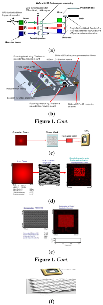
General schematic illustration of the suggested projection device may be seen in Figure 1(a). There, the projector is comprised from 3 lasers (red, NIR and blue) that are utilized to support red, green and blue (RGB) projected wavelengths where the green is obtained by frequency conversion done within the diode pumped solid state (DPSS) laser unit (pumped by the NIR laser diode). Nevertheless this projector may still maintain a toggling capability between stand alone NIR projection or a combination of a semi color projection with NIR.
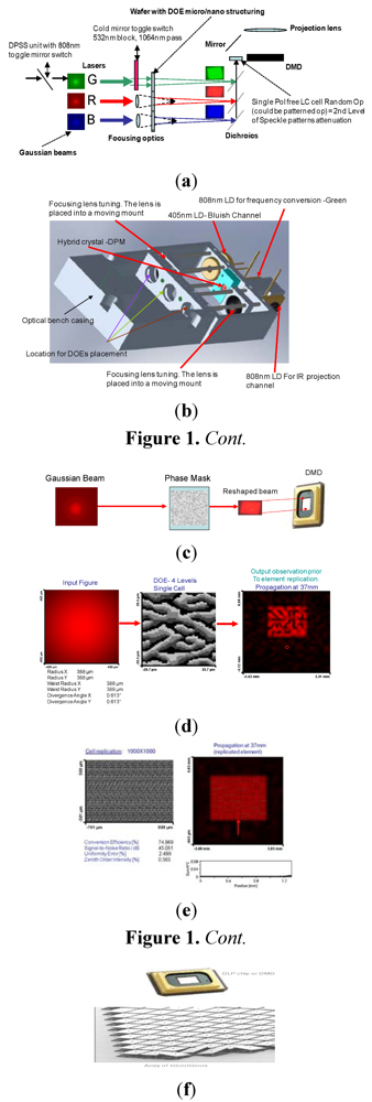
Figure 1.
Description of the various components of the micro projector. (a) The schematic sketch of the projector; (b) 3-D drawing of the constructed prototype; (c) The beam shaping phase diffractive optical element (DOE); (d,e) Experimental results for the beam shaping DOE; (f) The digital light processing (DLP) chip.
The DPSS laser emits two wavelengths of 532 nm and 1064 nm when no hot mirror is utilized to block the 1064 nm. Providing the option for a mechanical switch consisting of cold mirror, the user can block the 532 nm wavelength and allow free pass of the 1064 nm wavelength. This opens an opportunity for marking a target in NIR that is not easily detected by sensors of common cameras.
By mechanically switching the NIR to bypass the DPSS channel, the user can allow IR patterns projection or projection of any required data that can be utilized for 3-D measurements while simultaneously presenting information to the user in the VIS.
Altogether, these capabilities could be considered as drastic improvements of efficiency in comparison to existing systems having separated display and projection units in order to realize the same tasks.
In order to simply demonstrate the setup, we used RGB (as in the drawing of Figure 1(a)) without the toggling of 808 nm to bypass the DPSS channel. Instead, the DPM hybrid crystal (external resonator) can be pulled out from the bench (as seen in the drawing of Figure 1(b), mini-cage setting allows simple installation and removal of DPM-NdYVO4 + KTP crystals based chip) where different caps with collimator lenses can be placed in front of the 808 nm laser diode (LD). Note that the above mentioned crystals are used for the optical non linear conversion which converts the 1064 nm wavelength into the green lasing at wavelength of 532 nm.
The utilization of beam shaper for the DPSS channel, rather than diffractive optical element (DOE) for the other channels, is optional in order to better address multi-wavelength compatibility. In our demo we designed two DOEs (for wavelengths of 532 nm and 650 nm) which could be replaced on the optical bench. If not changed, this would still work with other wavelengths, but with added granularity and some effects to the aspect ratio of the reshaped figure.
In order to improve the energetic efficiency and the display performance of the proposed device, the emitted Gaussian beams were reshaped by only passing DOE that performed what is called Gaussian to Top Hat conversion in the distribution profile of the beam, through special phase. Such DOE is called Top Hat DOE [16,17]. The Top Hat distribution has rectangular cross section that is similar to the area of the surface of the DMD. Thus, this conversion between the laser’s emitted beam profile and the reshape of the DMD, over which the spatial light modulation is done, is the simplest way to realize an energetically efficient image projector.
Speckle is a known issue in laser based projection modules and it is known to bug the observers after prolonged view. In this paper we suggest DOE based utilization also for assisting in speckle effects attenuation if the DOE is physically moved by a piezo element which would ensure beam coverage changes across different cell groups in the element, similar to what happens using the moving diffuser technique. The slightest movement across the nano size cell groups would deliver a better averaging effect of the speckle pattern.
We also suggest unique consideration in the design of the DOE by which speckle patterns could be addressed in expense of performance that are functionality related. A nano structure topography of the element is smoothened by plasma etching technique assisting in affecting speckle reduction, however, it also affects other parameters in the functionality of the DOE. Since the DOE in this case is designed for illumination purpose only, running a procedure that would “ruin” the structure’s topography to some extent in favor of speckle patterns reduction is acceptable as part of the high frequencies manipulation and it would not affect the full functionality of the projection engine.
The schematic sketch of this operation can be seen in Figure 1(c) where the DOE is a phase only element converting the output beam to adapt with the DMD aspect ratio which is used to electrically modulate the input and to create the image we aim to project.
DOE can be designed using the Gerchberg-Saxton technique [18], in which two diffractive optical phase elements are separated by a free space propagation distance of Z. Instead of using a free space separation distance, a Fourier transform relation might also be used between the two planes. In our design we performed an optimization of one period and then replicated it to generate a uniform output of Top Hat distribution. Figure 1(d) displays the experimental results obtained for a 4-level DOE which is a single period. After its replication, we obtained the experimental results as presented in Figure 1(e).
The measurements in Figure 1(c,d) were performed for a targeted distance of ~37 mm between the beam shaping DOE and the DMD. The wavelength was NIR wavelength of 808 nm and the formation of reshaped figure of 4 × 3 mm was designed to cover the active area of the DMD. The DLP itself contributed to the high overall energetic efficiency by providing mirrors with fill factor of about 90% and with reflectivity level of close to 100%. The image of the DLP can be seen in Figure 1(f).
The utilization of lasers in 4 wavelength channels is an important feature in improving the energetic efficiency of the proposed projector in comparison to conventional spatially incoherent illumination source. First, due to the spatial coherence of the laser, the above mentioned beam shaping can be done efficiently. Beam shaping for spatially incoherent illumination is much more complicated and much less energetically efficient. Again, due to spatial coherence, the laser may be efficiently directed towards suitable beam expanding device and imaging lens, without having any energetic loss. Incoherent beams are much less confined in their angular distribution and thus they are less efficient in this sense. In addition, the projected image produced by the coherent source has much larger depth of focus (this extended depth of focus is obtained due to the preservation of the phase information in coherent illumination) and may be used for 3-D image display using the ability to direct the beam only to one eye of the observer at a time. To further explain this point, we wish to emphasize that although the depth of focus is strongly related to the numerical aperture (NA) of the imaging lens, it is also affected by the spatial coherence of the illumination. The reason is that when imaging with spatially coherent illumination, one deals with the CTF (coherent transfer function) of the imaging lens and the defocusing is expressed there as a parabolic phase function that does not block any spatial frequencies from passing through. In the spatially incoherent case, nevertheless, one talks about the OTF (optical transfer function), which, in the case of defocusing, has zero transmission values to some of the spatial frequencies.
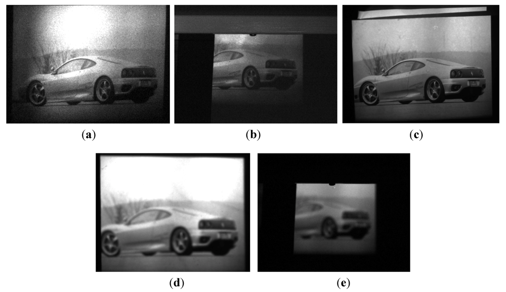
Experimental results demonstrating the extended depth of focus that may be obtained with spatially coherent versus incoherent imaging is shown in Figure 2. In the experiment, we have performed a projection of an image using laser (spatially coherent illumination) and using LED (spatially incoherent). The focus was set at a distance of 70 cm. The F number of the projector was 11. We imaged the result obtained over the screen (positioned at different distances) with camera having F number of 6. In Figure 2(a,b) we use the modified laser projection engine while the screen was positioned at distances of 70cm from the projector (i.e., at focus) and at 180 cm, respectively. In Figure 2(c–e) we use the stock LED based projection engine for realizing image projection over a screen positioned at distances of 70 cm, 90 cm and 180 cm (without changing the initially set focus point that was set to be at 70 cm) from the projector. From the obtained images one may see that when using the laser projector, even at 180 cm the image is still sharp and contains high resolution features (power limitation prevented us from increasing distance beyond 180 cm, nevertheless our visual observation showed even greater depth). When using LED on the other hand (at focusing setting of 70 cm), already at a distance of 90 cm from the projector, the image has drastically blurred.
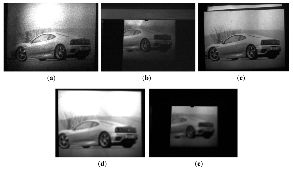
Figure 2.
Out of focus comparison between spatial coherent and spatial incoherent cases. (a) Laser projection obtained at a distance of 70 cm; (b) Laser projection obtained at a distance of 180 cm; (c) LED projection obtained at a distance of 70 cm; (d) LED projection obtained at a distance of 90 cm; (e) LED projection obtained at a distance of 180 cm.
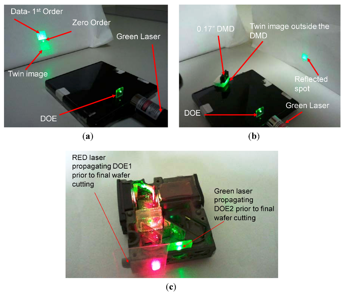
In Figure 3, we tested the functionality of various sub modules of the micro projector. Figure 3(a) presents a rectangular beam shaper that is based on multi level DOE in off axis data projection that is planned to match the shaped beam to the aspect ratio of the active area of the DMD. Figure 3(b) displays the outcome of the beam shaping testing procedure performed with the DOE and the DMD.
A twin image was visible due to having the off axis data close to the border of the design field. To further improve efficiency, it is possible to increase the field size (which would require changing feature size to reach the correct dispersion angle) or to move the data closer to the center. Figure 3(c) shows the tuning of visible green/red lasers with DOE and DMD setup.
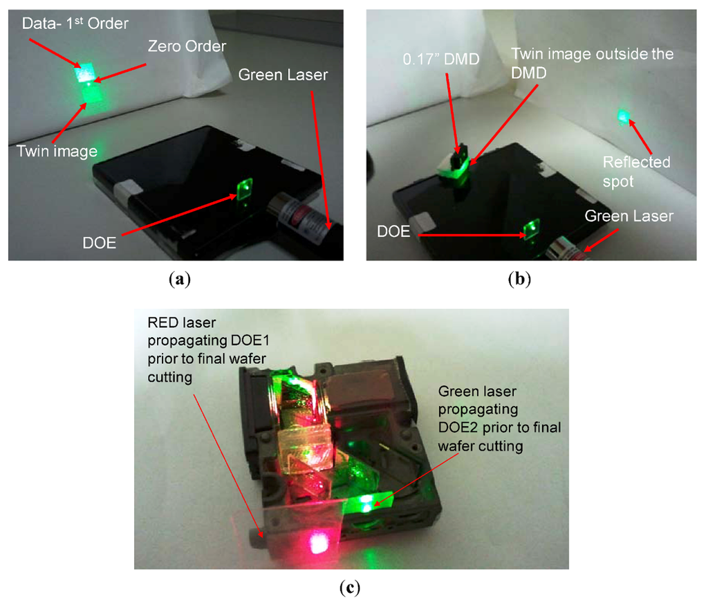
Figure 3.
(a) Rectangular beam shaper DOE projecting off axis data; (b) Beam shaper testing with DMD; (c) Tuning of the visible green/red lasers with DOE and DMD setup.
Figure 3.
(a) Rectangular beam shaper DOE projecting off axis data; (b) Beam shaper testing with DMD; (c) Tuning of the visible green/red lasers with DOE and DMD setup.
Coherency of the light allows directing the beam towards a certain spatial position without diffusing its spatial information to other sensors. Thus, the usage of two such micro projectors would allow a stereoscopic vision without a need for the observer to have special masking glasses. The information of the right eye will be transmitted to the right eye and the information of the left eye will be transmitted to the left eye. Due to the spatial coherency, the illumination is directional and the two different spatial distributions aimed for the two eyes will reach them without undesired cross talk between the two eyes. Such a system is sensitive to the gazing direction and thus an eye tracking system will be required. Nevertheless, this sensitivity is not extremely severe since the spot of light that transmits the information to each eye can be wider than the eye diameter. Even if it is as wide as the separation distance between the two eyes, no cross talk will be generated.
In order to reduce speckle resolution a common known approach would involve utilization of a moving holographic diffuser as part of the optical illumination. Producing a random pattern assists in reducing the contrast of the speckle patterns that are formed during the time of light integration done either by the detector or by the human viewer.
As part of the projection engine implementation, the reduction of the speckle patterns contrast especially in laser video projection is an important task. Now we briefly describe our approach in which we have successfully operated the DMD as a time varying diffuser to demonstrate how speckle patterns can be reduced without the use of any additional mechanical moving parts.
The presented architecture holds a key advantage in comparison to common approaches by its ability to shut off the speckle reduction algorithm by a push of a button. In addition, it allows the reduction of the contrast of the speckle patterns as part of the image projection configuration while no undesired artifacts such as diffuser’s granularities are added into the projected image (unlike obtained by other commonly used approaches for speckle’s contrast attenuation).
The ability to read the true speckle appearance when desired is an advantage that allows utilization of the speckle reading for varied future applications such as obtaining information from the projected surface (e.g., the 3D technique of Microsoft’s and PrimeSense Kinect’s module). The demonstrated light engine is basically multifunctional and serves as more than a display substitute. Such utilization has never been demonstrated and holds high flexibility in controlling the speckle phenomena especially in the fast rate switching DMD chips.
In the example presented in Figure 4(a,b), the DMD was fed with high rate random patterns. We have examined different cases in which the effect of random as well as partially random patterns was studied in respect to the resulting speckle appearance. Since the fastest DMD can be driven at 32 KHz, one of its major advantages is that it can be used simultaneously for the projection of the desired data (which can be time varying) while in between the frames we project randomized patterns to be used for the decrease in the speckle’s contrast. It is interesting to note that although in our case the random pattern injection was done by numerical computation, recently several approaches were developed in which the laser itself was used in order to realize a more randomized number generator [19]. This may indicate another advantage in using a laser based projector.
Specifically regarding the procedure for the speckle reduction, we designed a diffuser based on the DMD’s mirrors which were considered as the base feature size for the design. In order to reach maximum change in time sequence on a pixel level, we pushed the DMD to project random patterns coming from random pattern generator algorithm.
In our experiment we used the 0.17" DMD which can be driven at maximum refresh rate of 2.4 KHz. We used this rate to periodically (in time) display 8 different random patterns. The resulted speckle patterns were captured with VGA camera having lens with focal length of 16mm. The distance between the reflective screen and the DMD was 20 cm. Our experiment showed a reduction in the speckle contrast by 20%–30% (dependent on the type of surface/screen that was used prior to the applied speckle reduction procedure). Note that the obtained results can be further enhanced and what we showed is only a preliminary demonstration of the capabilities that the DMD module can offer in respect to speckle’s contrast reduction. Obviously changing our DMD (that was operated at 2.4 KHz) to DMD operating at 32 KHz will be very helpful.
In the left side of Figure 4(c), one may see the speckle patterns before applying the speckle reduction algorithm. In the right side, the result obtained after the reduction can be seen. See Figure 4(d) as additional confirmation of the efficiency of the applied technique in which we performed figure analysis of the projected spot before and after speckle attenuation. It is clearly visible how the high spatial frequency is attenuated as the speckle reduction procedure is applied. The experiment shown in Figure 4(c,d) was done for a lens with an F number of 1.4. In Figure 4(e–f) and in Figure 4(g–h) we repeated the same experiment but changed the F number of the lens of the camera to be 16 and 4 respectively.
In Figure 4(i) we present the DMD based experimental setup that we used in our experimental demonstration.

Figure 4.
(a) Speckle image; (b) The random pattern we fed to the DMD; (c) Left: An example of a speckle patterns before applying the speckle reduction algorithm, Right: after applying the algorithm. Experiment performed for imaging lens with F number of 1.4; (d) Projected spot figure analysis of before (left) and after (right) speckle attenuation is applied. It is clearly visible how the high spatial frequency is attenuated as the speckle reduction procedure is applied; (e,f) The same as (c) and (d) respectively, but for F number of 16; (g,h) The same as (c) and (d) respectively, but for F number of 4; (i) The experimental DMD based setup (TI’s D4100 professional Kit) that we used in our experiments.

3. Projector’s Testing
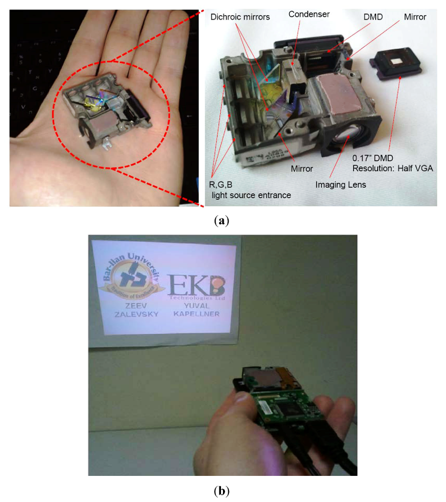
In order to investigate the theoretical low power-consuming concept, an experimental demonstrator was constructed as seen in Figure 5(a). We used Texas Instruments Discovery 4100 professional kit to allow maximal flexibility and simplified accessibility to the optical bench while running the experiment.
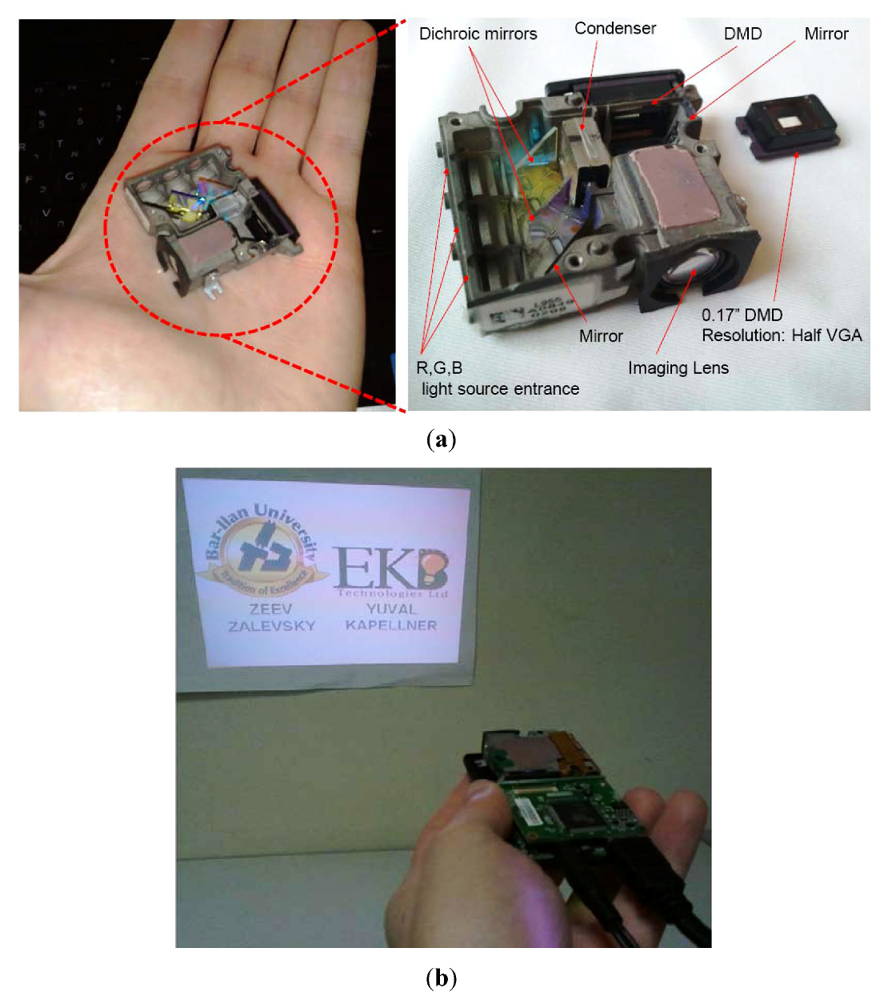
Figure 5.
Experimental results: (a) Construction of the micro projector; (b) Experimental image projection with average power consumption of 1.43 W for the RGB light sources and 1.2 W for the electronics. The obtainable output brightness is 10 lumens for 12" screen.
Figure 5.
Experimental results: (a) Construction of the micro projector; (b) Experimental image projection with average power consumption of 1.43 W for the RGB light sources and 1.2 W for the electronics. The obtainable output brightness is 10 lumens for 12" screen.
Based on the results, we repeated the experiment using the miniature size DLP PICO V2 development kit manufactured by YoungOptics [20,21,22,23,24] on which we had performed a customization procedure with the stock LEDs (light emitting diodes) based light engine by taking apart the original RGB LEDs and replacing them with new laser light sources, as well as modifying the optical route accordingly to allow efficient illumination across the DMD. This was performed in order to demonstrate a more efficient and innovative approach in delivering structured light capability for volume measurements with simultaneous visible image projection that were both done by the same single projection engine.
The demonstration resulted in a high depth of focus while opening new 3-D user interactivity possibilities and is an additional reason for making the proposed DMD based solution as an efficient and flexible replacement of different sizes of conventional miniature displays (such as LCD, LEP, OLED, etc.).
The procedure was performed by EKB Technologies Ltd who is a certified Texas Instruments DLP design house [25].
Specifically, the demonstrator contained three lasers (in red, green and near IR) and one LED (in blue). All the above described components were packaged in a device having a volume of less than 10 cm3. The DMD that was integrated was 0.17” in size producing half VGA projection resolution.
The overall electronic average power consumption of the prototype included 1.43 W for the RGB light sources (operated at color sequential mode) and additional 1.2 W for the electronics. This produced overall brightness of 10 lumens on a 12" screen (for the above mentioned color sequential operation mode). This power consumption is more than ten times lower than the power consumption of a conventional screen having identical dimensions and brightness. Please note that the distribution of the lumens between the different colors is not uniform (since this division is wavelength dependent, e.g., the eye is much more sensitive to the green than to the blue) so the overall of 10 lumens does not mean that each color had 3.3 lumens.
The experiment yielded the projection image that is displayed in Figure 5(b).
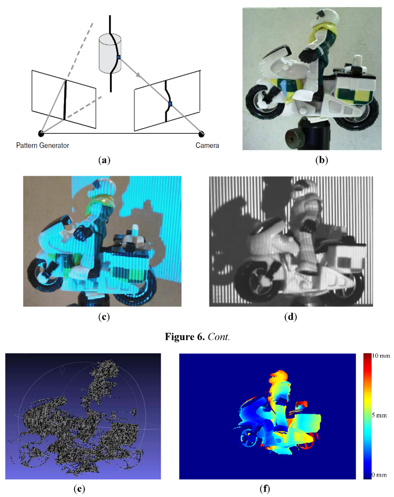
Figure 6.
(a) Schematic sketch of 3-D reconstruction scenario using a projector and an imaging camera; (b) The modelled object; (c) Pattern projection in the visible; (d) Pattern projection in the IR; (e) Point cloud 3-D reconstruction; (f) 3-D reconstruction where color change signifies changes in topography.
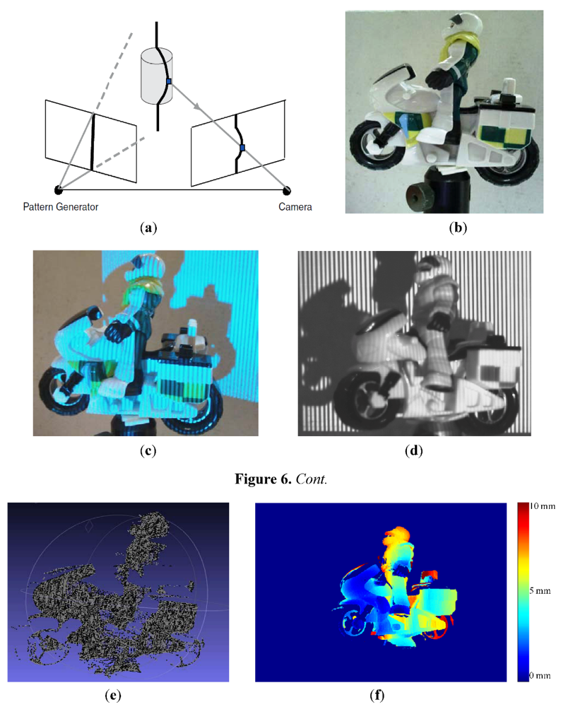
One possible application of a projector can combine a camera for volume measurement (3-D modeling) by projecting various patterns (as lines) via the projector and examining how the patterns are deformed [26,27] A schematic sketch of such a configuration can be seen in Figure 6(a). The resolution of this 3-D estimation process is triangulation related while the triangulation is between the projector and the imaging camera. We used our micro projector with an imaging camera to demonstrate this 3-D estimation capability. In Figure 6(b) we present the modeled object. In Figure 6(c) one may see the pattern projection in the visible range. In Figure 6(d) we show the pattern projection in the IR. In Figure 6(e) and 6(f) we present the obtained reconstruction while 6(e) is a point cloud and 6(f) is a display in which color change signify changes in topography.
This experiment was performed at a measurement distance of 23 cm from the projector. The resolution was HVGA (320 × 480 pixels). The accuracy of the obtained reconstruction was about 2.5 mm. For the reconstruction, we projected (using the constructed micro projector) 22 binary patterns with changeable spatial density.
Modeling measurements were examined by physically measuring an actual object and comparing it with the obtained computerized outcome based on structured light. We have observed an average accuracy of 2.5 mm depending on the capturing conditions especially the texture and the environmental ambient light interferences.
The setup included a true imaging camera model DMK 21AF04 which consisted of pixels resolution of 640 × 480. The required resolution is dependent on the size of the modeled object and the smallest feature size that needs to be resolved. Higher resolution allows larger areas to be scanned while still resolving small features. The speed requirement is driven by the maximum amount of time allowed for the system to finish a complete reading (measuring) and eventually to render the outcome. This parameter is especially important if one projects high number of patterns or if the modeled object is moving.
As a part of the procedure, a calibration stage was needed when no object was measured and only the background reading was taken for the given fixed setting of the camera and projector (extrinsic parameters would need to be recalculated if the relative positions between the pattern generator and the camera change). After capturing the reflected patterns, the images are then processed to obtain the required information. The patterns are decoded by matching the value of a specific pixel on the camera to the value that is supposed to be projected for that specific pixel. Once those correspondences are established, the depth information for each imaged point can be determined by triangulation.
Note that in the discussed experimental results of Figure 6, the 3-D reconstruction is based upon triangulation while the projector, the object and the camera define a triangle. The projector can be combined together with the imaging camera to allow estimation of ranges by projecting Z varied patterns [28,29]. In this case, since the projected patterns vary with Z, the specific pattern reflected from the object will designate the range to the object.
4. Conclusions
This paper presents the technological description, as well as several experimental testing, of a portable micro projector prototype serving as a critical component in the construction of low power consuming computing systems.
The proposed projector provides about 3 lumens per Watt and its overall power consumption is more than 10 times less than the power consumption of similar conventional computer displays. In the experimental results presented in this paper, we have been able to demonstrate projection brightness of 10 lumens.
In addition, due to usage of a laser (spatially coherent source) as the illumination source, the device could also be used to provide extended projected depth of focus. It can also be used for 3D illustrations when different images are projected directly to each of the two eyes of the observer (the coherent illumination is directional as opposed to an incoherent one, and thus the illumination can be formed in such a way that different images will directionally be projected in each of the two eyes of the observer. This will create a 3D perception.). Further, the device could be used for volume measuring, such as ranging and object’s topography estimation.
References
- Rolland, J.P.; Yoshida, A.; Davis, L.D.; Reif, J.H. High-resolution inset head-mounted display. Appl. Opt. 1998, 37, 4183–4193. [Google Scholar]
- Rolland, J.P.; Krueger, M.W.; Goon, A. Multifocal Planes Head-Mounted Displays. Appl. Opt. 2000, 39, 3209–3215. [Google Scholar]
- Hua, H.; Girardot, A.; Gao, C.; Rolland, J.P. Engineering of head mounted projective display. Appl. Opt. 2000, 39, 3814–3824. [Google Scholar]
- Ha, Y.; Rolland, J. Optical assessment of head mounted displays in visual space. Appl. Opt. 2002, 41, 5282–5289. [Google Scholar] [CrossRef]
- Howlett, E.M. High resolution inserts in wide angle head mounted stereoscopic displays. SPIEProc. 1992, 1669, 193–203. [Google Scholar]
- Hua, H.; Ha, Y.; Rolland, J.P. Design of an ultra light and compact projection lens. Appl. Opt. 2003, 42, 97–107. [Google Scholar] [CrossRef]
- Kelly, T.H.; Mucci, M.G.; Rector, B.; Sears, T. Initial performance data of portable scene projector. SPIE Proc. 2001, 4366, 140–146. [Google Scholar]
- Slobodin, D.E.; Biber, C. Ultra portable projector progress and prospects. SPIE Proc. 2000, 3954, 19–26. [Google Scholar]
- Urey, H. Diffractive exit pupil expander for display applications. Appl. Opt. 2001, 40, 5840–5851. [Google Scholar] [CrossRef]
- Karpman, M.S.; Wells, B.A. Virtual displays for entertainment applications: Hitting cost/performance with LED arrays. SPIE Proc. 1997, 3000, 161–198. [Google Scholar]
- Zalevsky, Z.; Kapellner, Y.; Sabo, E.; Kapellner, S. Virtual display with low power consuming portable micro projector. SPIE Proc. 2003, 5002, 154–163. [Google Scholar]
- Kapellner, Y.; Kapellner, S.; Pomerantz, I.; Zalevsky, Z.; Sabo, E. Image Projecting Device and Method. U.S. Patent 7128420, 31 October 2006. [Google Scholar]
- Sharon, I.; Zalevsky, Z.; Manor, G.; Kapellner, Y. Image Projecting Device and Method. U.S. Patent 7746559, 29 June 2010. [Google Scholar]
- Raskar, R.; Brown, M.S.; Ruigang, Y.; Wei-Chao, C.; Welch, G.; Towles, H.; Scales, B.; Fuchs, H. Multi-Projector Displays Using Camera-Based Registration. In Proceedings of the Visualization ’99, San Francisco, CA, USA, 29 October 1999; pp. 161–168.
- Cotting, D.; Naef, M.; Gross, M.; Fuchs, H. Embedding Imperceptible Patterns into Projected Images for Simultaneous Acquisition and Display. In Proceedings of the 3rd IEEE and ACM International Symposium on Mixed and Augmented Reality (ISMAR 2004), Arlington, VA, USA, 2-5 November 2004; pp. 100–109.
- Kley, E.B.; Cumme, M.; Wittiq, L.C.; Thieme, M. Beam shaping elements for holographic applications. SPIE Proc. 2000, 4179, 58–64. [Google Scholar]
- Zhang, S.; Ren, Y.; Lupke, G. Beam shaping of ultra short laser pulses using diffractive optics: A theoretical study. SPIE Proc. 2002, 4770, 89–95. [Google Scholar]
- Zalevsky, Z.; Mendlovic, D.; Dorsch, R.G. Gerchberg-Saxton algorithm applied in the fractional Fourier or the Fresnel domains. Opt. Lett. 1996, 21, 842–844. [Google Scholar]
- Reidler, I.; Aviad, Y.; Rosenbluh, M.; Kanter, I. Ultra high speed random number generation based on a chaotic semiconductor laser. Phys. Rev. Let. 2009, 103. [Google Scholar] [CrossRef]
- Texas Instruments. DLP & MEMS. DLP design kits (including Pico). Available online: http://focus.ti.com/analog/docs/memsmidlevel.tsp?sectionId=622&tabId=2447 (accessed on 2 March 2012).
- Texas Instruments. DLP Technology. Available online: http://focus.ti.com/analog/docs/memsmidlevel.tsp?sectionId=622&tabId=2442 (accessed on 2 March 2012).
- Texas Instruments. Introduction to Digital Micro Mirror Device. Available online: http://focus.ti.com/lit/an/dlpa008/dlpa008.pdf (accessed on 2 March 2012).
- Texas Instruments. Using DLP® Development Kits for 3D Optical Metrology Systems. Available online: http://focus.ti.com/lit/an/dlpa026/dlpa026.pdf (accessed on 2 March 2012).
- Texas Instruments. Using PICO kit for structured light applications. Available online: http://www.ti.com/lit/an/dlpa021a/dlpa021a.pdf (accessed on 2 March 2012).
- Texas Instruments. DLP® 0.17 HVGA DDR Series 210 DMD. Available online: http://www.ti.com/lit/ds/dlps018b/dlps018b.pdf (accessed on 2 March 2012).
- Besl, P. Active optical range imaging sensors. Mach. Vis. Appl. 1998, 1, 127–152. [Google Scholar] [CrossRef]
- Horn, E.; Kiryati, N. Toward Optimal Structured Light Patterns. In Proceedings of the International Conference on Recent Advances in 3-D Digital Imaging and Modeling, Ottawa, Canada, 12-15 May 1997; pp. 28–37.
- Sazbon, D.; Zalevsky, Z.; Rivlin, E. Qualitative real-time range extraction for preplanned scene partitioning using laser beam coding. Pat. Rec. Lett. 2005, 26, 1772–1781. [Google Scholar] [CrossRef]
- Duadi, H.; Gordon, E.; Bittan, G.A.; Loven, A.; Zalevsky, Z. Correlation based interpolation technique for accurate 3-D estimation via projection of axially varied patterns. 3D Res. 2011, 2, 1–6. [Google Scholar]
© 2012 by the authors; licensee MDPI, Basel, Switzerland. This article is an open-access article distributed under the terms and conditions of the Creative Commons Attribution license (http://creativecommons.org/licenses/by/3.0/).
