Article

Active Quasi-Circulator Based on Wilkinson Power Divider for Low-Power Wireless Communication Systems

EHF Key Laboratory of Fundamental Science, School of Electronic Science and Engineering, University of Electronic Science and Technology of China, Chengdu 611731, China
*
Author to whom correspondence should be addressed.
J. Low Power Electron. Appl. 2025, 15(4), 58; https://doi.org/10.3390/jlpea15040058
Submission received: 9 July 2025 / Revised: 17 September 2025 / Accepted: 24 September 2025 / Published: 1 October 2025

Abstract

This paper presents a microstrip active quasi-circulator designed for low-power wireless communication systems. The circuit consists of a second-order Wilkinson power divider and two power amplifiers with high gain and ultra-low noise characteristics. By leveraging the unidirectional transmission characteristics of the transistors and the isolation provided by resistors within the power divider, the interference between the transmitter (TX) and receiver (RX) is effectively suppressed. Additionally, thanks to the dual-amplifier architecture, no extra power amplification circuitry is required, thereby reducing the overall complexity and power consumption of the communication system. The detailed design procedure of the proposed quasi-circulator is presented. The measurement results show that, within the frequency range of 4.75 GHz to 6.11 GHz, the isolation between the TX and RX ports exceeds 20 dB, the return loss at each port is greater than 10 dB, and the transmission gains from the TX port to the antenna and from the antenna to the RX port are 3.1–8.7 dB and 2.7–4.0 dB, respectively, demonstrating a relative bandwidth of 25%.

1. Introduction

A circulator is a passive three-port or multi-port electromagnetic (EM) device with asymmetric transmission characteristics. Its primary function is to enable unidirectional signal flow, meaning that the input signal entering one port can only propagate through a specific path to another port and cannot return to the input port [1]. Circulators are widely used in wireless communication systems, allowing the transmit (TX) and receive (RX) links to share a single antenna (ANT) while maintaining isolation between them. This helps reduce the number of antennas required, thereby lowering the system’s cost and complexity [2].
Traditional circulators are typically made from magnetic materials, such as ferrites, which have the disadvantages of being bulky and difficult to integrate [3]. To achieve the integration of circulators, two new technologies for magnetless circulators have been developed. The first is the transistor-based active circulator, which can provide signal gain and compensate for transmission losses, but it suffers from issues such as high noise and poor linearity [4,5,6]. The second is the magnetic-free circulator based on linear periodic time-varying circuits, which offers good noise performance and linearity, but has limitations such as high insertion loss and narrow bandwidth [7,8,9,10,11]. This work focuses on the active quasi-circulator (AQC). An active quasi-circulator is a special type of active circulator, particularly suitable for wireless communication systems, with its three ports connected to the TX, RX, and ANT in the system [12,13,14,15]. Signals are transmitted from the TX port to the ANT port, and from the ANT port to the RX port, but no power is transmitted from the TX port to the RX port (as shown in Figure 1). The active quasi-circulator, while reducing technical complexity, enables the TX and RX to share a single ANT while maintaining isolation between them.
Currently, quasi-circulators are mainly divided into two categories based on their implementation technologies. The first category includes active quasi-circulators formed by transistors and in-phase or out-of-phase power combiners [16,17,18,19,20]. A microstrip active quasi-circulator composed of two common amplifier modules and two power couplers is proposed in [17]. The power couplers utilize parallel coupling lines with slow-wave structures to improve isolation between the quasi-circulator ports. The measurement results show that the insertion loss of the quasi-circulator in the operating frequency band ranges from 1 to −2 dB, with isolation greater than 20 dB. However, the structure still faces the issue of having a large overall size. An active quasi-circulator module consisting of two unidirectional general-purpose amplifiers and an inverting power splitter/combinator is presented [18]. The unidirectional characteristics of the amplifiers and power divider enable unidirectional signal propagation. A quasi-circulator structure composed of two isolators and a Wilkinson power divider (WPD) [19]. The isolators limit the direction in which the signal can travel, whereas the Wilkinson power divider provides primary isolation between the TX and RX ports. This design encounters issues like limited bandwidth and significant insertion loss. To address this, a quasi-circulator structure utilizing a lumped Wilkinson power divider has been proposed [20]. The design consists of a power amplifier, a Wilkinson power divider, and a low-noise amplifier. The test results indicate that the quasi-circulator achieves over 29.5 dB isolation between the TX and RX ports, with transmission gains of 4.1 dB and 7.8 dB in the TX-to-ANT and ANT-to-RX directions, respectively. However, the structure still suffers from limited bandwidth. The second category is based on the principle of phase cancellation, which generates a cancellation signal that is 180° out of phase with the interfering signal to achieve isolation between TX and RX [21,22,23,24,25,26,27]. However, it is often challenging to balance wide bandwidth, insertion loss, and isolation performance.
This paper presents the design of an active quasi-circulator that combines wideband characteristics, low insertion loss, and high isolation performance. The structure employs a second-order Wilkinson power divider and two power amplifiers with high gain and ultra-low noise characteristics. This design effectively suppresses mutual interference between transmit and receive signals by utilizing the unidirectional conduction property of transistors and the isolation effect of the resistors in the power divider. Additionally, the dual-amplifier configuration eliminates the need for additional power amplification circuits. Measurement results indicate that the active quasi-circulator achieves a 25% relative bandwidth, with an isolation greater than 20 dB between the TX and RX ports. The transmission gains from TX to antenna and from antenna to RX are 3.1–8.7 dB and 2.7–4.0 dB, respectively, and the return loss at each port is better than 10 dB. The structure of this paper is as follows: In Section 2, the circuit design process is thoroughly elaborated, covering the second-order Wilkinson power divider, receive amplifier circuit, transmit amplifier circuit, and the integrated design of an active quasi-circulator; Section 3 presents and analyzes the experimental results; and Section 4 summarizes and discusses the work and outlook of the study.

2. Circuit Design

2.1. Topological Structure

The proposed circuit configuration, illustrated in Figure 2, primarily comprises three parts: the power division circuit, the TX circuit, and the RX circuit. To broaden the AQC’s operating bandwidth, a second-order WPD is used. Both the transmitting and receiving amplifier circuits employ BFP740 (Infineon, Beijing, China) transistors, known for their high gain and low noise, making them ideal for high-performance wireless communication applications. The EM signal is initially introduced through the TX; it is then passed through the transmit input matching circuit, the transmit amplifier circuit, and the transmit output matching circuit, before finally being delivered to one branch of the power splitter. As a result of the isolation effect of the resistors (R1 and R2) in the power distribution circuit, most of the signal is transmitted to the power combining port. Similarly, the EM signals received by the antenna are also input through the power combining port. Because of the resistors’ isolation effect in the power distribution circuit and the transistor’s one-way transmission property, the signal can only pass through the receiving branch. As a result, the circuit effectively prevents interference between transmitting and receiving signals by leveraging the transistor’s unidirectional conduction and the resistors’ isolation in the power distribution, thereby achieving the function of a quasi-circulator. Furthermore, a key benefit of this circuit is that it amplifies both received and transmitted EM signals through two transistor amplifiers, removing the requirement for a separate signal power amplification stage and greatly enhancing the overall efficiency of the circuit design.
The gain between TX and ANT, the gain between ANT and RX, the isolation from TX to RX port, and the isolation from RX to TX port can be expressed by Equations (1), (2), (3), and (4), respectively. GPA, GLNA, IsoPA, and IsoLNA represent the gain and reverse isolation of the power amplifier (PA) and low-noise amplifier (LNA), while IsoWPD represents the isolation of the power divider. Equation (1) indicates that when the electromagnetic signal from TX is input to the PA, the signal power is increased by GPA, and after passing through the power distribution circuit, fifty percent of the EM power is delivered to the ANT port. While the remaining power is dissipated in the resistors. Equation (3) shows that when the electromagnetic signal from TX leaks into RX through the power distribution circuit, it is amplified by both the PA and LNA while being attenuated through the resistors in the power distribution circuit. Therefore, PA and LNA do not need to be designed with high gain, as this would reduce the isolation between the TX and RX ports [20].
G T X A N T = G P A 3 dB
G A N T R X = G L N A 3 dB
I s o T X R X = I s o W P D G P A G L N A
I s o R X T X = I s o L N A + I s o W P D + I s o P A

2.2. Design of the Second-Order Wilkinson Power Divider

The power distribution circuit, which is the passive section of the entire active quasi-circulator, is implemented based on a WPD. According to Equation (3), to achieve high isolation between the transmitting and receiving circuits, the isolation of the power distribution circuit must be sufficiently high. Additionally, to extend the operating bandwidth of the active quasi-circulator, a second-order Wilkinson power divider with wider bandwidth characteristics and higher isolation is employed.
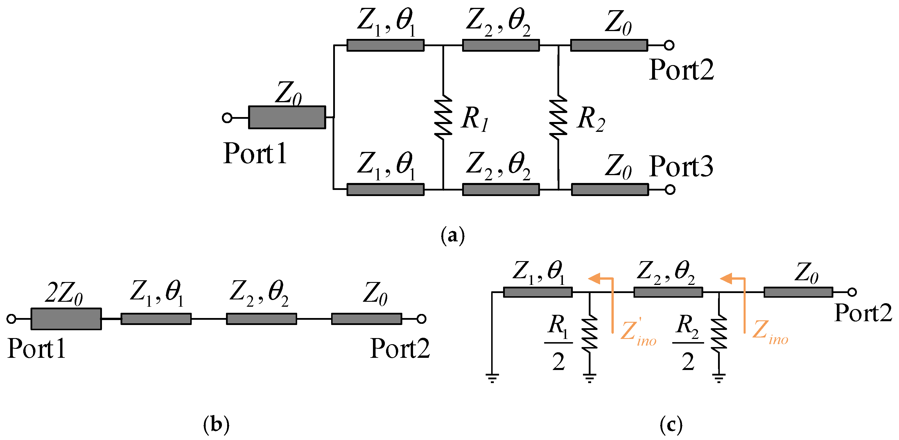
The equivalent transmission line model of the second-order two-way WPD is given in Figure 3. This circuit is analyzed using the odd-even mode analysis method. Under even-mode excitation, the circuit exhibits symmetric behavior, with no current flowing through the isolation resistor, which behaves like an open circuit. At this point, the simplified equivalent circuit model is shown in Figure 3b. For port 1, the odd-mode excitation has no effect, so the reflection coefficient at port 1 is the same as the magnitude of the reflection coefficient in the even-mode equivalent circuit. It can be seen that the even-mode equivalent circuit is equivalent to a quarter-wavelength step impedance transformer with an impedance ratio of 2 at both ends. Within the operating bandwidth, the circuit is set to satisfy the Chebyshev ripple characteristic, with a relative bandwidth of 90%. From the table, we find that Z1 = 62 Ω and Z2 = 80 Ω.
Under odd-mode excitation, the center of the isolation resistor becomes grounded; the corresponding simplified equivalent circuit is presented in Figure 3c. With θ1 = θ2, the reflection coefficient at port 2 can be calculated using the following formula based on transmission line theory:
Z i n o = j R 1 Z 1 tan θ 1 R 1 + j 2 Z 1 tan θ 1
Z i n o = Z 2 R 2 ( Z i n o + j Z 2 tan θ 2 ) Z 2 ( 2 Z i n o + R 2 ) + j ( 2 Z 2 2 + R 2 Z i n o ) tan θ 2
Γ i n o = Z i n o Z 0 Z i n o + Z 0 = a 1 + j b 1 a 2 + j b 2
where
a 1 = R 1 R 2 Z 0 Z 2 + Z 1 R 1 R 2 Z 0 2 R 2 2 Z 0 Z 2 2 tan θ 2 2
b 1 = Z 2 2 R 2 Z 0 Z 1 + R 1 R 2 2 Z 0 Z 1 + Z 2 tan θ 2
a 2 = R 1 R 2 Z 0 Z 2 Z 1 R 1 R 2 Z 0 + 2 R 2 + 2 Z 0 Z 2 2 tan θ 2 2
b 2 = Z 2 2 R 2 Z 0 Z 1 + R 1 R 2 + 2 Z 0 Z 1 + Z 2 tan θ 2
There exist θ1 = θ2 = θ3 such that the reflection coefficient is zero, at which point a1 = 0 and b1 = 0. From this, R1 and R2 can be determined as follows:
R 1 = 2 Z 1 Z 2 tan θ 3 Z 2 ( Z 1 + Z 2 ) + ( Z 1 2 + Z 1 Z 2 ) tan θ 3 2
R 2 = 4 Z 0 Z 1 Z 2 2 tan θ 3 2 R 1 Z 0 Z 2 + ( R 1 Z 0 Z 1 + 2 Z 1 Z 2 2 ) tan θ 3 2
Based on the linear mapping relationship between the reflection coefficient and the second-order Chebyshev polynomial (|T2(x)| = |2x2 − 1|), θ3 can be determined as follows:
θ 3 = 90 ° 1 1 2 f 2 / f 1 1 f 2 / f 1 + 1
where f1 and f2 are the passband edge frequencies.
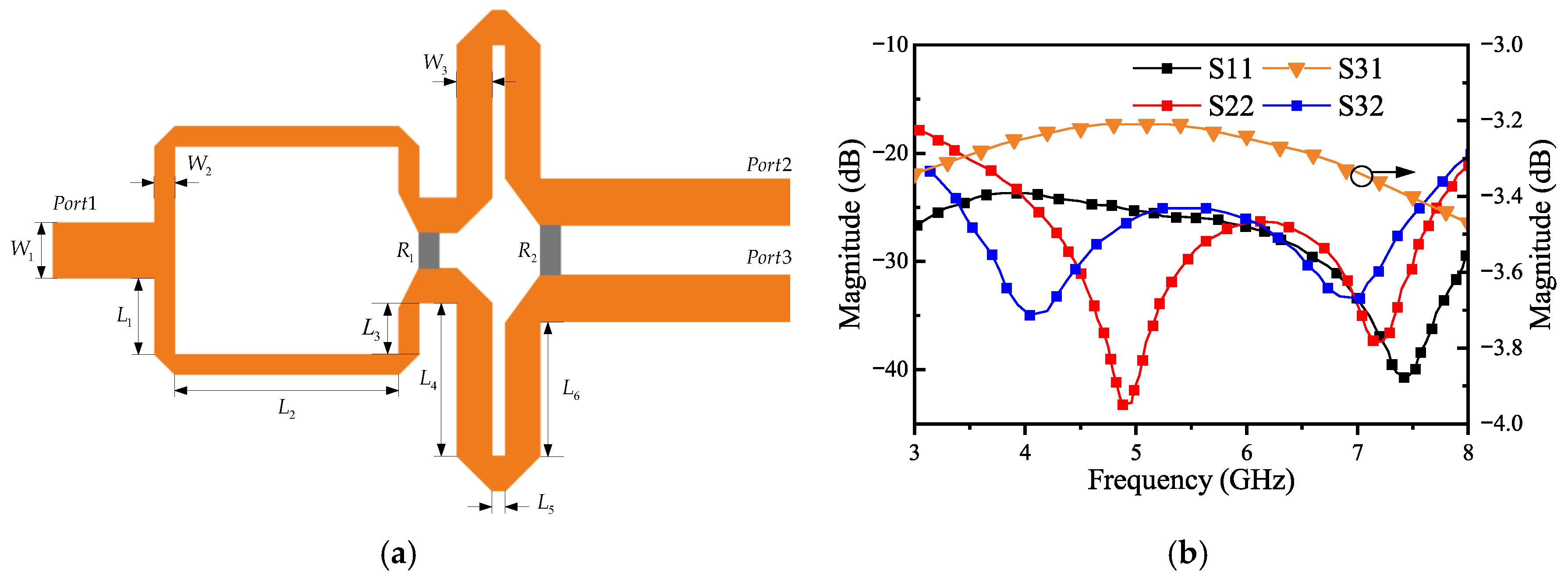
In this paper, the edge frequencies are f1 = 3  GHz and f2 = 8  GHz, which results in θ3 = 61°, R1 = 117  Ω, and R2 = 171  Ω. Considering the practical values of the resistors, R1 = 100 Ω and R2 = 200  Ω are chosen. These parameter values are used as the initial values for simulation optimization, with an FR4 dielectric substrate having a thickness of 0.6 mm and a relative permittivity of 4.4. The circuit layout and simulated S-parameters of the second-order Wilkinson power divider are shown in Figure 4. Over the frequency range of 3 GHz to 8 GHz, the circuit achieves an insertion loss below 3.5 dB, with both input and output return losses and isolation exceeding 20 dB. Additionally, the isolation response exhibits two distinct peaks.

2.3. Modeling and Simulation of Active Quasi-Circulation

Following the design of the isolation circuit, the transceiver amplifiers within the quasi-circulator must be simulated. The performance of these amplifiers depends heavily on their core active devices. Transistor selection follows several key principles: suitability for the target circuit, availability of complete parametric data, and a favorable balance between performance and cost. To minimize the effect of transistor noise on electromagnetic signal reception and transmission, the low-noise transistor BFP740 from Infineon was selected. This device offers excellent noise performance, high gain, and strong linearity across the 5–6 GHz band. Specifically, at 5.5 GHz, the BFP740 achieves a noise figure below 0.85 dB (at 3 V, 6 mA) and provides over 15 dB of gain (at 3 V, 12 mA). Furthermore, its SOT-343 package is both economical and facilitates straightforward soldering.
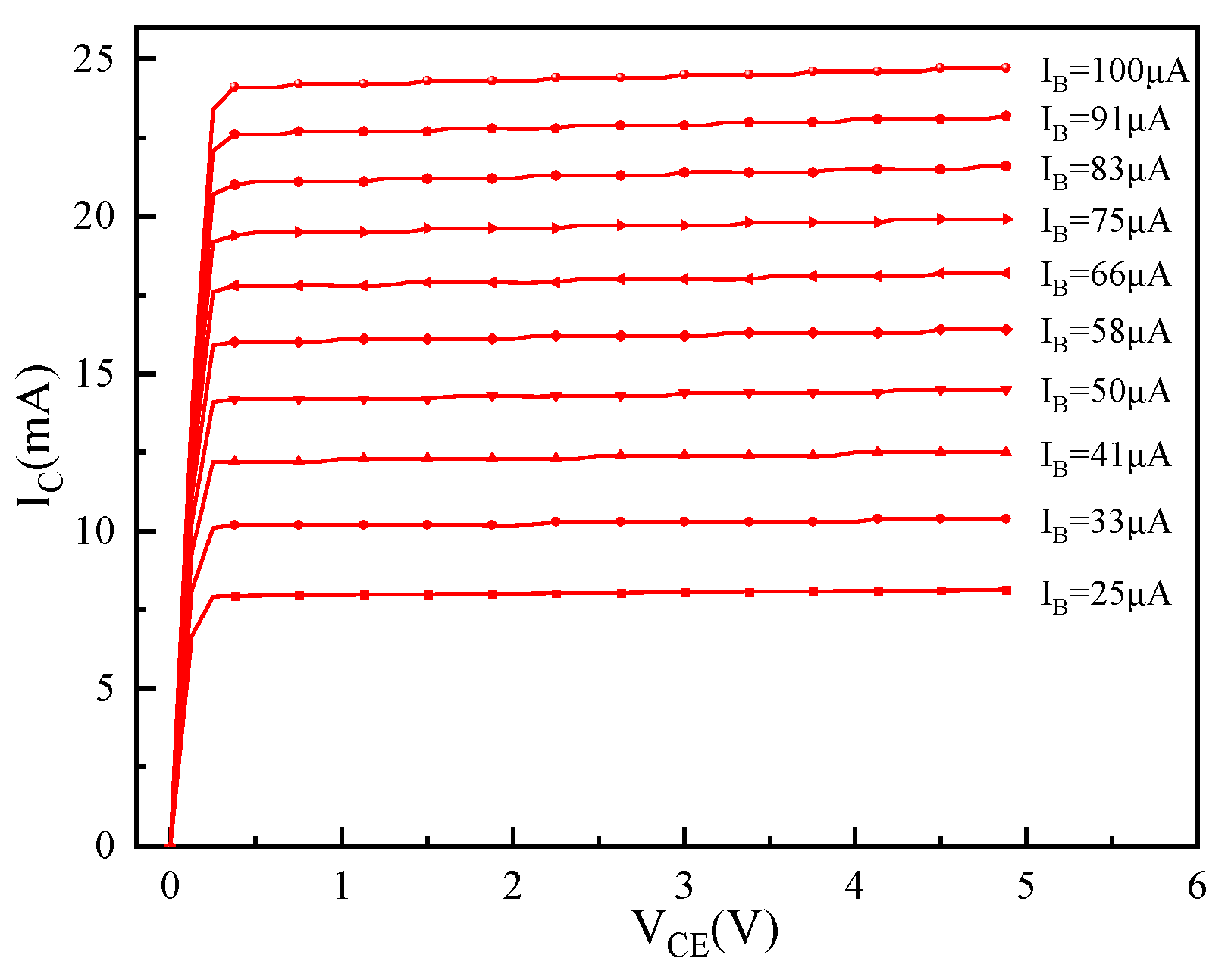
Upon selection of the suitable transistor, a DC scan (Figure 5) was conducted to identify its optimal operating point. Establishing an appropriate static operating point is essential for the correct operation of both the receiver and transmitter amplifier circuits, and serves as the foundation for designing the bias network. According to the transistor datasheet and simulation data, the final DC operating point was chosen at Vce = 3 V and Ic = 10 mA.
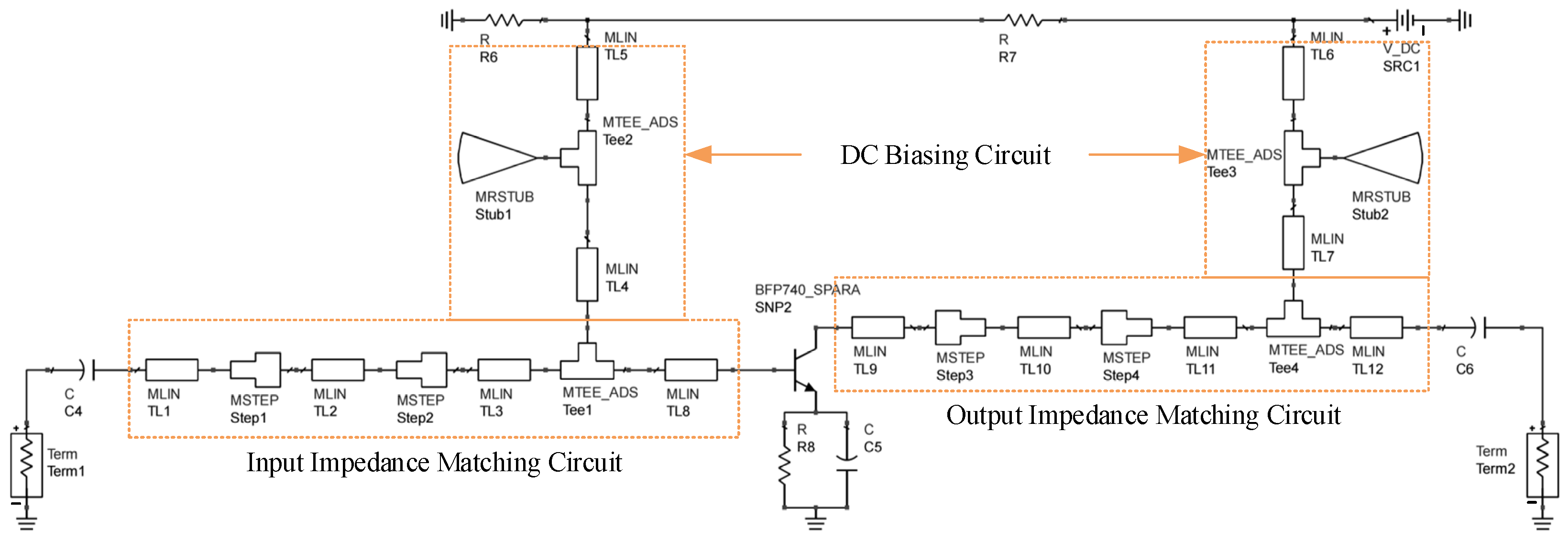
The receiving amplifier circuit consists of a DC biasing circuit, an input/output matching network, and a negative feedback stabilization circuit, as shown in Figure 6. The primary function of the DC biasing circuit is to isolate the RF signal while allowing DC to pass through. A classic λ/4 high-impedance line in parallel with a λ/4 fan-shaped open-line structure is employed. The DC biasing circuit decouples the DC bias from the RF path, ensuring the RF impedance remains unaffected. The circuit is powered by a 5 V single supply and utilizes three resistors (R5, R6, and R7) for voltage division to achieve the required DC operating voltage. A 100 pF DC blocking capacitor is placed at both the input and output to isolate the signal from the DC power supply. This input/output matching network ensures the seamless transmission of the RF signal from the power splitter port to the transistor, and subsequently from the transistor to the output port. A high-low impedance matching network is utilized, where the length and width of the microstrip lines are optimized to achieve proper impedance matching.
The negative feedback stabilization circuit is employed to ensure the stability of the amplifier’s operating state and effectively prevent the occurrence of oscillations. This circuit implements negative feedback through the configuration of an emitter resistor and a parallel capacitor. The principle of the emitter resistor’s negative feedback is as follows: when the output current increases, the emitter current also increases, resulting in a rise in emitter voltage. As the emitter voltage increases, the voltage difference between the base and emitter decreases, which in turn suppresses the increase in base current and limits the growth of the collector current. The primary function of the parallel capacitor is to stabilize the amplifier’s gain and improve its frequency response. At low frequencies, the capacitor behaves like an open circuit, thereby not affecting the negative feedback action of the emitter resistor and ensuring stable gain. At high frequencies, the capacitor provides a low-impedance path for the signal, thus eliminating the effect of the emitter resistor on the high-frequency signal gain, preventing gain degradation, and ensuring stable amplifier operation. WithAdvanced Design System (version 2024) simulation, the stability of the amplifier circuit can be assessed using the stability control parameter StabFact. When the stability factor K > 1, the amplifier circuit is considered to operate stably.
The simulated performance of the receiving amplifier is illustrated in Figure 7. Within the 4.5–6.5 GHz frequency band, the return loss |S11| ranges from 9 dB to 25 dB, the transmission gain |S21| varies from 8.6 dB to 13.0 dB, and the reverse isolation |S12| is greater than 25 dB. This indicates that the receiving circuit possesses a relatively wide impedance matching bandwidth and is capable of effectively achieving unidirectional signal transmission and electromagnetic signal amplification. From the stability curve, it can be observed that the operating state of the receiving circuit is stable.
After completing the design of the receiving amplifier circuit, the next step is to design the transmitting amplifier circuit. Due to the opposite directions of the transistors in the transmitting and receiving circuits, the receiving circuit cannot be directly applied to the transmitting circuit, necessitating a redesign and simulation. However, the circuit design principles and methods for both are the same. Consequently, high-low impedance lines remain employed in the transmitter amplifier to achieve optimal matching; the simulation schematic is provided in Figure 8.
The simulated performance of the transmit amplifier circuit is shown in Figure 9. In the 4.5–6.5 GHz frequency band, the return loss |S11| ranges from 6 dB to 40 dB, the transmission gain |S21| varies from 10.4 dB to 16.0 dB, and the reverse isolation |S12| is greater than 25 dB. This indicates that the transmitting circuit is capable of unidirectional signal transmission and amplification. The circuit’s impedance matching performance meets the design requirements. The stability curve confirms that the circuit operates in a state of absolute stability.
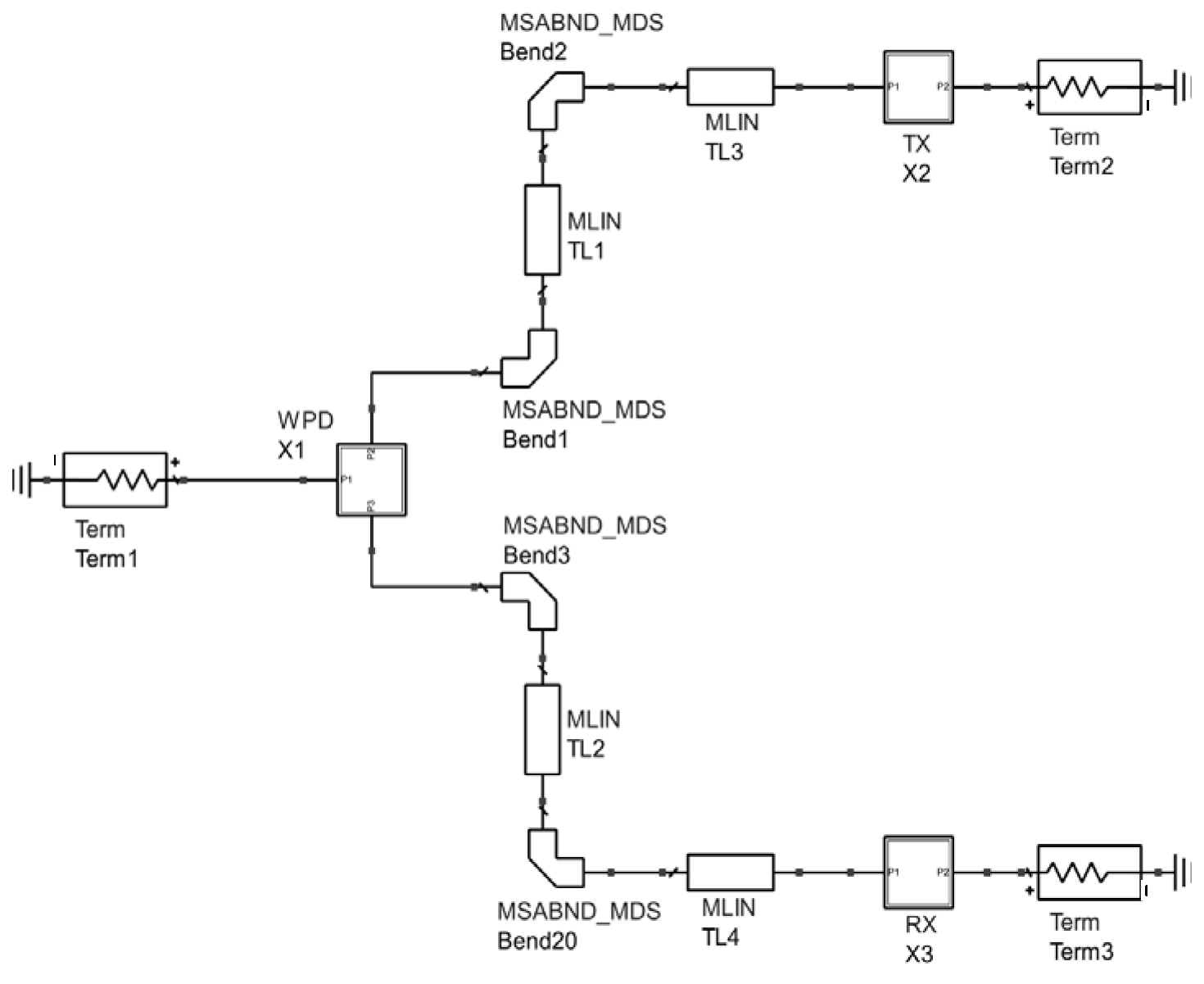
Following the simulation of each AQC circuit section, overall optimization is necessary. To simplify the schematic simulation, the second-order WPD, receiving amplifier circuit (RX), and transmitting amplifier circuit (TX) are each exported as symbols, as shown in Figure 10. By adjusting the length of the output port of the power distribution circuit, a reasonable layout is achieved for the connection between the receiving and transmitting amplifier circuits.
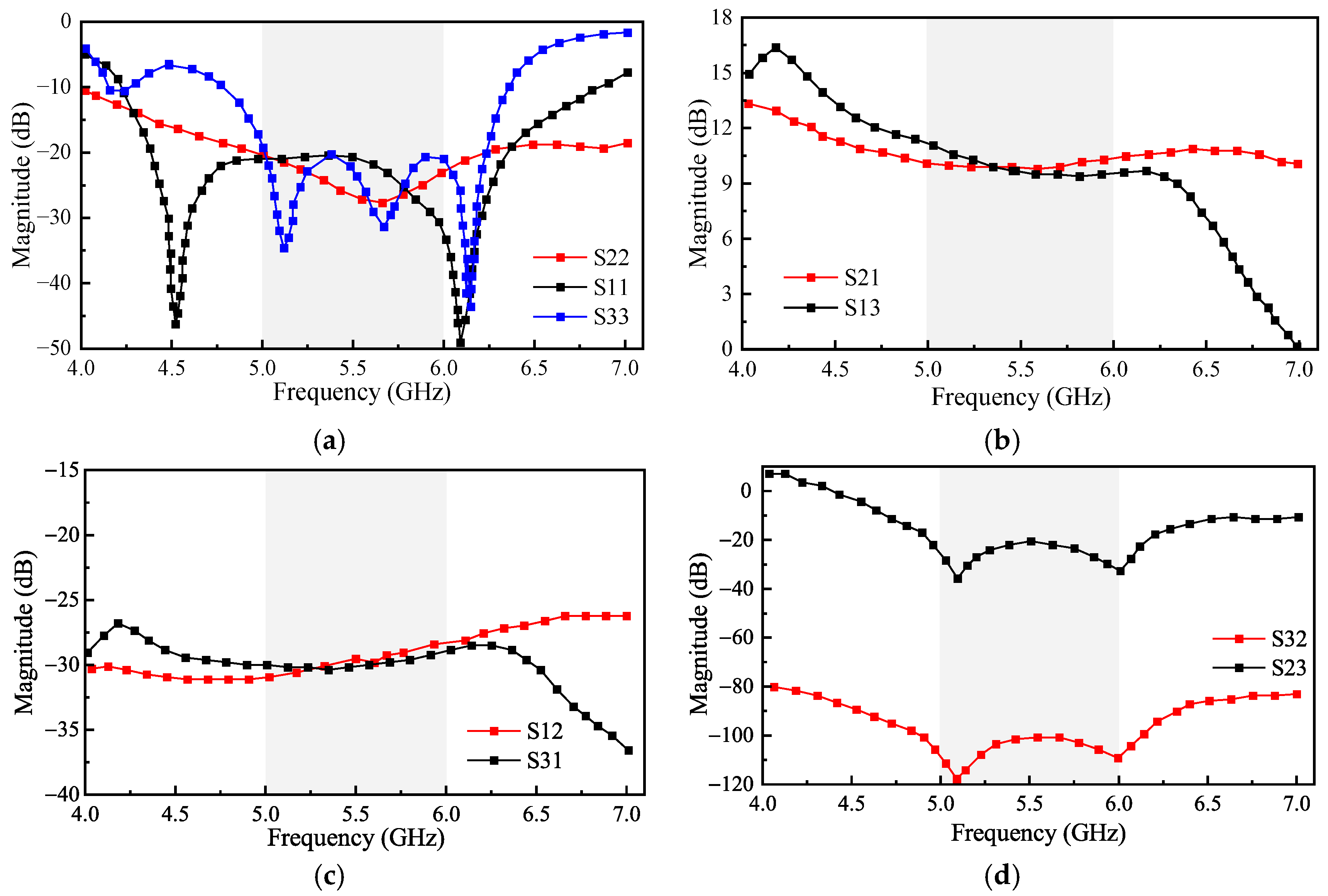
The overall simulation results of the AQC are presented in Figure 11. As depicted in Figure 11a, the return loss (|S11|, |S22|, and |S33|) at each port exceeds 20 dB across the 5–6 GHz band, demonstrating good port matching and efficient signal entry. Figure 11b indicates that the transmission gains (|S21| and |S13|) of both the receiving and transmitting amplifiers are above 9 dB. Meanwhile, Figure 11c reveals a reverse isolation (|S12| and |S31|) of over 25 dB in the operating band, confirming effective unidirectional signal transmission and suppression of reverse propagation. Finally, as illustrated in Figure 11d, the isolation between the receiver and transmitter amplifiers (|S32| and |S23|) remains greater than 20 dB from 5 to 6 GHz, ensuring minimal interference during simultaneous signal transmission and reception.
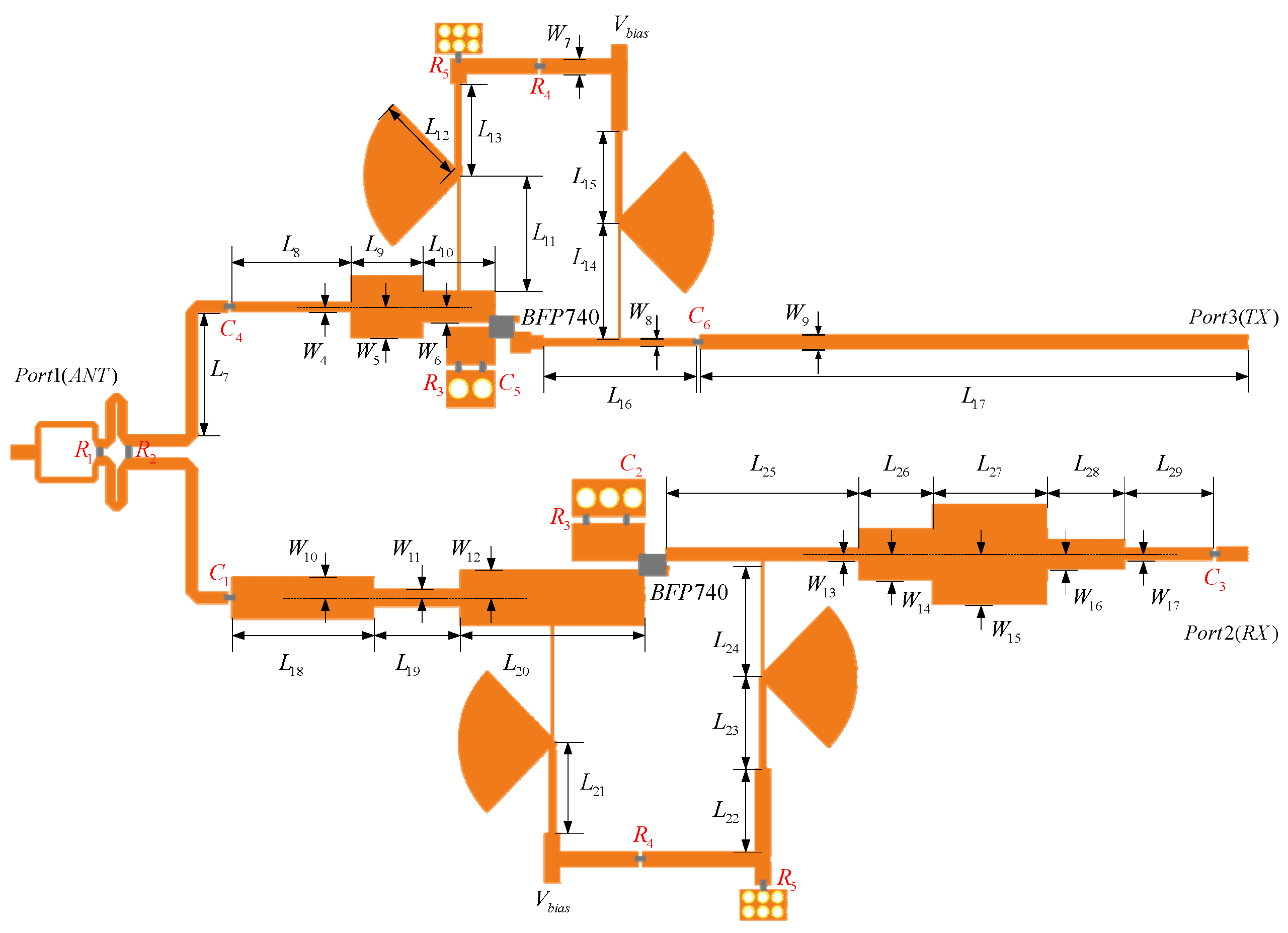
The preceding simulation data were obtained from the schematic design of the quasi-circulator, an approach valued for its computational speed and efficiency. However, actual circuit performance depends heavily on component selection and physical layout. To more accurately model real behavior, a schematic-layout co-simulation was conducted, as shown in Figure 12. The finalized structural dimensions and parameters of the AQC are listed in Table 1. During layout optimization, particular emphasis was placed on refining passive components—especially mitigating electromagnetic coupling between microstrip lines-to maintain intended circuit performance.
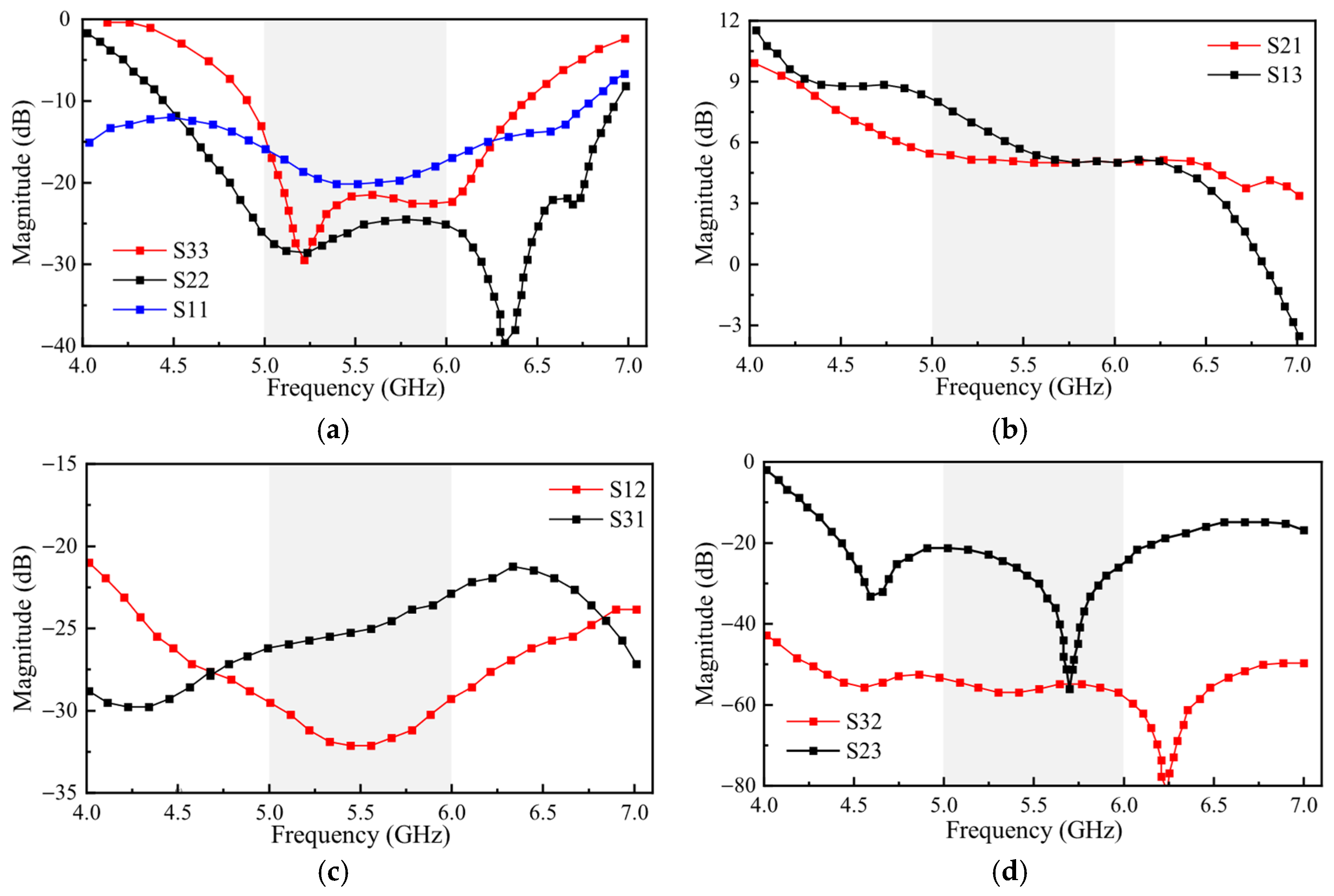
By optimizing the layout of the quasi-circulator, the final simulation results were obtained, as shown in Figure 13. As seen in Figure 13a, within the 5 GHz to 6 GHz frequency band, the port return loss (|S11|, |S22|, and |S33|) exceeds 15 dB, suggesting excellent impedance matching and efficient signal entry in all three channels of the quasi-circulator. From Figure 13b, it can be observed that the transmission gains of the receiving amplifier circuit and transmitting amplifier circuit (|S21| and |S13|) are both greater than 4.9 dB in the 5 GHz to 6 GHz frequency band, suggesting that the active quasi-circulator operates stably and is capable of amplifying the electromagnetic signal to a certain level. Figure 13c shows that the reverse isolation (|S12| and |S31|) is greater than 20 dB across the operating frequency band, indicating that the quasi-circulator can achieve unidirectional electromagnetic signal transmission. Figure 13d demonstrates that the isolation between the receiving amplifier circuit and the transmitting amplifier circuit (|S32| and |S23|) is greater than 20 dB in the 5–6 GHz frequency band, ensuring that electromagnetic signals do not interfere with each other during transmission and reception. By comparing the schematic and layout simulation results, it can be seen that the performance difference between the schematic and layout of the quasi-circulator circuit is minimal, fully meeting the design requirements and specifications.

3. Measurement and Discussion

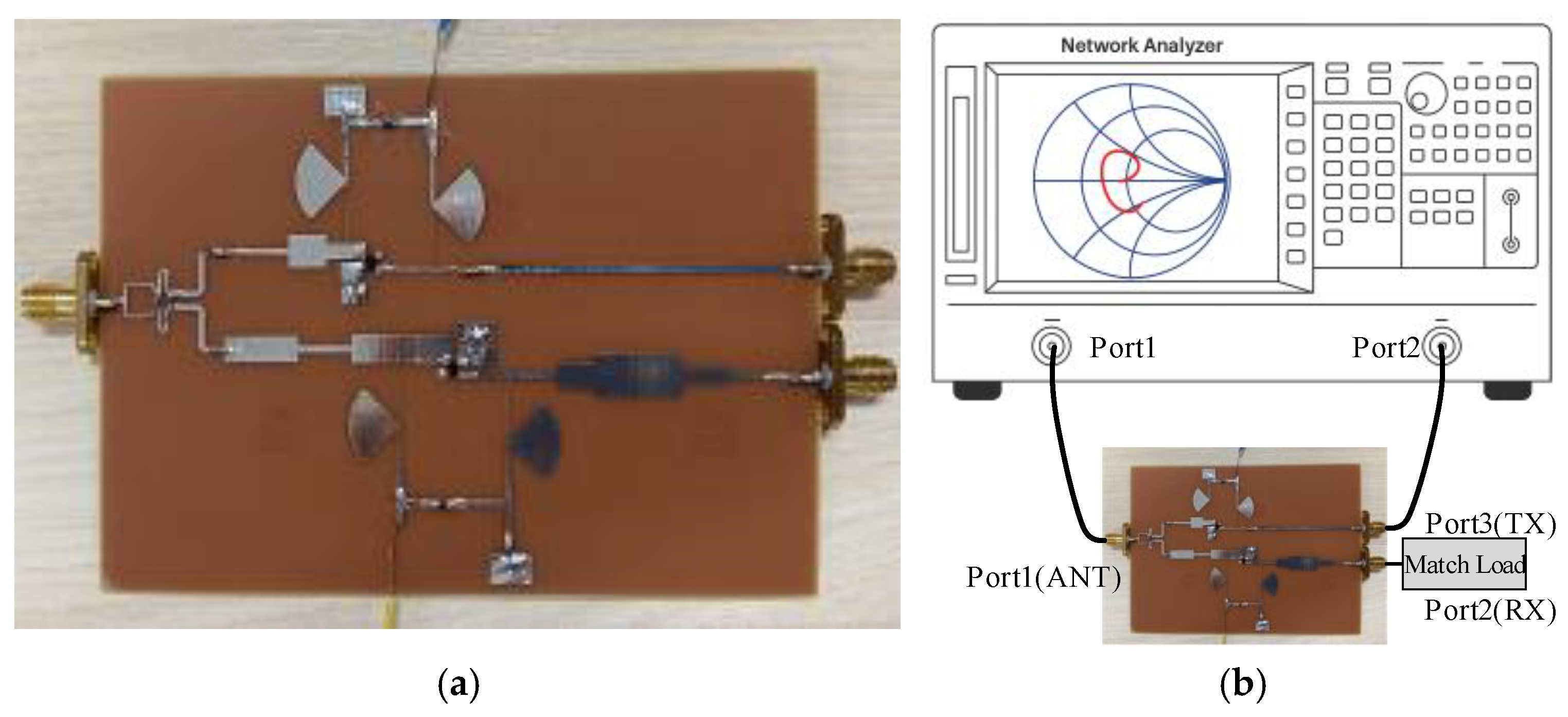
The simulation-optimized AQC was fabricated and experimentally characterized. The circuit was implemented on an FR4 dielectric substrate with a thickness of 0.6 mm, a relative dielectric constant of 4.4, and a loss tangent of 0.02. S-parameter measurements were carried out using a DC power source and an Agilent N5244 vector network analyzer (Agilent Technologies, Santa Clara, CA, USA). A photograph of the fabricated circuit is provided in Figure 14.
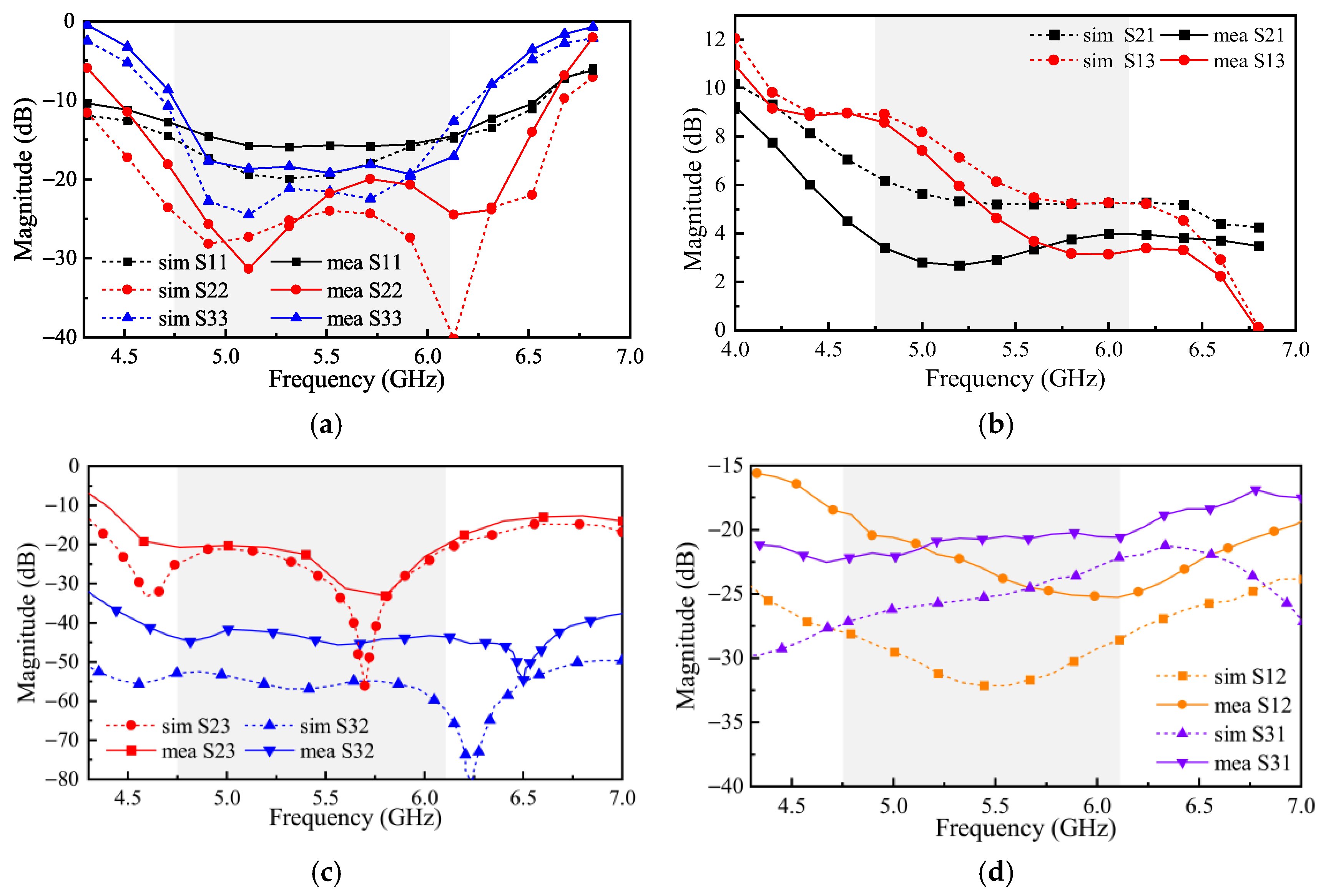
The simulated and measured performance of the AQC is compared in Figure 15. Across the frequency band from 4.75 GHz to 6.11 GHz, the return loss at each port (|S11|, |S22|, and |S33|) remains above 10 dB, indicating good port matching and efficient signal entry across all three channels. The transmission gains between the TX-to-antenna and antenna-to-RX paths (|S21| and |S13|) range from 3.1 to 8.7 dB and 2.7–4.0 dB, respectively, demonstrating stable amplification in both receive and transmit chains. Isolation between the TX and RX ports (|S23| and |S32|) exceeds 20 dB, ensuring minimal interference during operation. The active quasi-circulator achieves a relative bandwidth of 25%. Minor discrepancies between simulation and measurement are attributed to substrate permittivity variation, fabrication tolerances, and connector soldering, yet the overall performance shows good agreement.
The performance comparison between the proposed circuit and existing circulators is given in Table 2. Compared with active quasi-circulators based on the phase-cancelation principle (references [24,25,27]), the proposed active quasi-circulator provides forward transmission gain across the entire operating frequency band, with transmission gains reaching up to 8.7 dB at certain frequency points, significantly outperforming other designs. Unlike the CMOS technology employed in references [13,24,25], the proposed design utilizes PCB technology, offering lower cost and more convenient processing advantages. Furthermore, the operating frequency band of the proposed active quasi-circulator is 4.75–6.11 GHz (C-band), which is suitable for modern wireless communication, particularly the 5G frequency band. Therefore, the core innovation of the proposed quasi-circulator lies in maximizing the gain of the active circulator, effectively addressing the high insertion loss problem associated with traditional circulators, while also balancing high-frequency performance, excellent isolation, and the cost advantages offered by PCB technology.

4. Conclusions

This work introduces an AQC featuring a compact, integration-friendly topology and strong RF performance. The design combines the WPD structure and the unidirectional transmission characteristics of transistors. Receive/transmit paths are isolated using a pair of resistors, while stepped-impedance networks provide impedance matching to maintain low-loss transmission at each port. A dual-amplifier arrangement enables in-line gain, removing the need for a separate power-amplifier stage, which both simplifies the overall system and reduces power draw. A fabricated prototype was measured and compared with simulation, showing closely aligned results and confirming reliable operation across 4.75–6.11 GHz.

Author Contributions

Conceptualization, K.S. and X.C.; methodology, X.C.; software, X.C.; validation, X.C. and Z.H.; formal analysis, X.C.; investigation, Z.H.; resources, Z.H.; data curation, X.C.; writing—original draft preparation, Z.H.; writing—review and editing, X.C.; visualization, X.C.; supervision, K.S.; project administration, K.S.; funding acquisition, K.S. All authors have read and agreed to the published version of the manuscript.

Funding

This research was funded by the National Natural Science Foundation of China, grant number 62171097, and the Natural Science Foundation of Sichuan Province of China, grant number 2024NSFSC0463.

Data Availability Statement

The original contributions presented in this study are included in the article. Further inquiries can be directed to the corresponding author.

Conflicts of Interest

The authors declare no conflicts of interest.

References

  1. Tang, T.; Zhang, X.; Aldhaeebi, M.A.; Almoneef, T.S. Design of X-Band Circulator and Isolator for High-Peak-Power Applications. Micromachines 2024, 15, 916. [Google Scholar] [CrossRef]
  2. Mi, C.; Zhao, C.; Liu, Z.; Luo, T.; Huang, C.; Agrawal, D.K.; Zhang, Y.; Huang, K. Compact Four-Port Waveguide Circulator Using Discrete Ferrites for Injection-Locking Magnetron System. Electronics 2024, 13, 997. [Google Scholar] [CrossRef]
  3. AbdElraheem, M.; Shams, S.; Elsaadany, M.; Gagnon, G.; Kishk, A. High-Power Circulator: Assembly Design and Challenges. IEEE Trans. Microw. Theory Tech. 2022, 70, 4354–4364. [Google Scholar] [CrossRef]
  4. Tanaka, S.; Shimomura, N.; Ohtake, K. Active circulators—The realization of circulators using transistors. Proc. IEEE 1965, 53, 260–267. [Google Scholar] [CrossRef]
  5. Carchon, G.; Nanwelaers, B. Power and noise limitations of active circulators. IEEE Trans. Microw. Theory Tech. 2000, 48, 316–319. [Google Scholar] [CrossRef]
  6. Mung, S.; Chan, W. The Challenge of Active Circulators: Design and Optimization in Future Wireless Communication. IEEE Microw. Mag. 2019, 20, 55–66. [Google Scholar] [CrossRef]
  7. Estep, N.; Sounas, D.; Soric, J.; Alù, A. Magnetic-free non-reciprocity and isolation based on parametrically modulated coupled-resonator loops. Nat. Phys. 2014, 10, 923–927. [Google Scholar] [CrossRef]
  8. Reiskarimian, N.; Zhou, J.; Krishnaswamy, H. A CMOS Passive LPTV Nonmagnetic Circulator and Its Application in a Full-Duplex Receiver. IEEE J. Solid-State Circuits 2017, 52, 1358–1372. [Google Scholar] [CrossRef]
  9. Yu, Y.; Michetti, G.; Kord, A.; Pirro, M.; Sounas, D.; Xiao, Z.; Cassella, C.; Alu, A.; Rinaldi, M. Highly-Linear Magnet-Free Microelectromechanical Circulators. Microelectromech. Syst. 2019, 28, 933–940. [Google Scholar] [CrossRef]
  10. Zhang, B.; Wu, C.; Gao, Y. Design and test of a MEMS magnetic-free circulator based on bulk acoustic-wave resonators. In Proceedings of the 2021 IEEE International Conference on Manipulation, Manufacturing and Measurement on the Nanoscale (3M-NANO), Xi’an, China, 2–6 August 2021; pp. 307–310. [Google Scholar] [CrossRef]
  11. Dinc, T.; Krishnaswamy, H. 17.2 A 28 GHz magnetic-free non-reciprocal passive CMOS circulator based on spatio-temporal conductance modulation. In Proceedings of the 2017 IEEE International Solid-State Circuits Conference (ISSCC), San Francisco, CA, USA, 5–9 February 2017; pp. 294–295. [Google Scholar] [CrossRef]
  12. Tang, S.; Liu, X.; Jiang, Y.; Guan, J.; Li, P.; Han, J. Design of a Broadband and High-Isolation CMOS Active Quasi-Circulator. Appl. Sci. 2024, 14, 10083. [Google Scholar] [CrossRef]
  13. Chen, Y.; Li, Y.; Huang, Z.; Li, X. Design of an X-band Active Quasi-Circulator in CMOS Technology. In Proceedings of the 2023 International Conference on Microwave and Millimeter Wave Technology (ICMMT), Qingdao, China, 14–17 May 2023; pp. 1–3. [Google Scholar] [CrossRef]
  14. Tang, B.; Gui, X.; Xu, J.; Xia, Q.; Yang, H.; Geng, L. A Wideband Active Quasi-Circulator with 34-dB Isolation and Insertion Loss of 2.5 dB. IEEE Microw. Wirel. Compon. Lett. 2020, 30, 693–696. [Google Scholar] [CrossRef]
  15. Tang, B.; Gui, X.; Xu, J.; Xia, Q.; Geng, L. A Dual Interference-Canceling Active Quasi-Circulator Achieving 36-dB Isolation Over 6-GHz Bandwidth. IEEE Microw. Wirel. Compon. Lett. 2019, 29, 409–411. [Google Scholar] [CrossRef]
  16. Wu, H.; Wang, C.; Tzuang, C. CMOS Active Quasi-Circulator with Dual Transmission Gains Incorporating Feedforward Technique at K-Band. IEEE Trans. Microw. Theory Tech. 2010, 58, 2084–2091. [Google Scholar] [CrossRef]
  17. Saavedra, C.; Zheng, Y. Active quasi-circulator realisation with gain elements and slow-wave couplers. IET Microw. Antennas Propag. 2007, 1, 1020–1023. [Google Scholar] [CrossRef]
  18. Bahri, R.; Abdipour, A.; Moradi, G. Aalysis and Design of New Active Quasi Circulator and Circulators. Prog. Electromagn. Res. 2009, 96, 377–395. [Google Scholar] [CrossRef]
  19. Chang, J.; Kao, J.; Lin, Y.; Wang, H. Design and Analysis of 24-GHz Active Isolator and Quasi-Circulator. IEEE Trans. Microw. Theory Tech. 2015, 63, 2638–2649. [Google Scholar] [CrossRef]
  20. Wang, S.; Wu, Y. Wilkinson power divider-based cmos quasi-circulator for single-antenna radar systems. Microw. Opt. Technol. Lett. 2016, 58, 2065–2068. [Google Scholar] [CrossRef]
  21. Hung, S.; Cheng, K.; Wang, Y. An Ultra Wideband Quasi-Circulator with Distributed Amplifiers Using 90 nm CMOS Technology. IEEE Microw. Wirel. Compon. 2013, 23, 656–658. [Google Scholar] [CrossRef]
  22. Mung, S.; Chan, W. Self-equalization technique for distributed quasi-circulator. Microw. Opt. Technol. Lett. 2009, 51, 182–184. [Google Scholar] [CrossRef]
  23. Ghosh, D.; Kumar, G. A Broadband Active Quasi Circulator for UHF and L Band Applications. IEEE Microw. Wirel. Compon. 2016, 26, 601–603. [Google Scholar] [CrossRef]
  24. Wang, S.; Lee, C.; Wu, Y. Fully Integrated 10-GHz Active Circulator and Quasi-Circulator Using Bridged-T Networks in Standard CMOS. IEEE Trans. Very Large Scale Integr. VLSI Syst. 2016, 24, 3184–3192. [Google Scholar] [CrossRef]
  25. Zheng, Y.; Saavedra, C. Active Quasi-Circulator MMIC Using OTAs. IEEE Microw. Wirel. Compon. 2009, 19, 218–220. [Google Scholar] [CrossRef]
  26. Shin, S.; Huang, J.; Lin, K.; Wang, H. A 1.5–9.6 GHz Monolithic Active Quasi-Circulator in 0.18 μm CMOS Technology. IEEE Microw. Wirel. Compon. 2008, 18, 797–799. [Google Scholar] [CrossRef]
  27. Mung, S.; Chan, W. Novel Active Quasi-Circulator with Phase Compensation Technique. IEEE Microw. Wirel. Compon. Lett. 2008, 18, 800–802. [Google Scholar] [CrossRef]
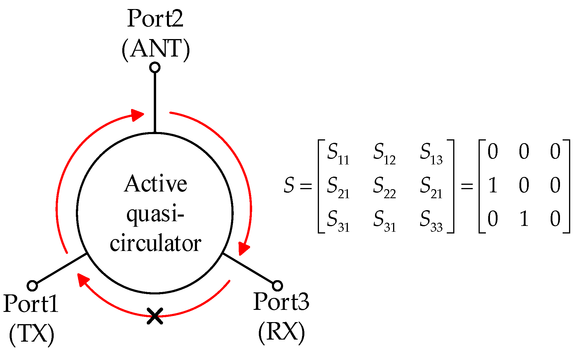
Figure 1. Functional block diagram and S-parameters of the active quasi-circulator.
Jlpea 15 00058 g001
Figure 2. The topology of the active quasi-circulator (AQC).
Jlpea 15 00058 g002
Figure 3. The topological structure of a 2-order Wilkinson power divider (WPD): (a) Topological structure of the circuit; (b) Even-mode analysis of the WPD; (c) Odd-mode analysis of the WPD.
Jlpea 15 00058 g003
Figure 4. The Second-Order WPD: (a) circuit layout, (b) simulation results.
Jlpea 15 00058 g004
Figure 5. DC characteristic curve.
Jlpea 15 00058 g005
Figure 6. Receiving amplifier circuit structure.
Jlpea 15 00058 g006
Figure 7. Simulated performance of the receiver amplifier: (a) S-parameters; (b) stability factor.
Jlpea 15 00058 g007
Figure 8. Transmitting amplifier circuit structure.
Jlpea 15 00058 g008
Figure 9. Simulated performance of the transmit amplifier circuit: (a) S-parameters; (b) stability factor.
Jlpea 15 00058 g009
Figure 10. Schematic diagram of the complete active quasi-circulator circuit.
Jlpea 15 00058 g010
Figure 11. Schematic simulation results of the complete active quasi-circulator: (a) The ports’ power reflection responses; (b) The ports’ power transmission responses; (c) Reverse Isolation; (d) TX-RX Isolation.
Jlpea 15 00058 g011
Figure 12. The layout of the active quasi-circulator.
Jlpea 15 00058 g012
Figure 13. Layout simulation results of the complete active quasi-circulator: (a) The ports’ power reflection responses; (b) The ports’ power transmission responses; (c) Opposite isolation of ports; (d) Isolation between receive and transmit ports.
Jlpea 15 00058 g013
Figure 14. Fabrication and measurement of the circuit: (a) Photograph of the fabricated circuit; (b) Measurement setup.
Jlpea 15 00058 g014
Figure 15. Simulation and measurement results of the active quasi-circulator: (a) The ports’ power reflection responses; (b) The ports’ power transmission responses; (c) Reverse Isolation; (d) TX-RX Isolation.
Jlpea 15 00058 g015
Table 1. Physical dimensions (mm) and electrical component values of the active quasi-circulator.
Para 1L1L2L3L4L5L6L7L8L9
Value1.54.40.93.10.32.610105.9
ParaL10L11L12L13L14L15L16L17L18
Value697.479712.645.811.8
ParaL19L20L21L22L23L24L25L26L27
Value7.215.276.779166.29.4
ParaL28L29W1W2W3W4W5W6W7
Value6.57.41.10.40.70.431.30.6
ParaW8W9W10W11W12W13W14W15W16
Value0.51.11.71.72.20.5242.2
ParaW17R1R2R3R4R5C1~6
Value0.5100 Ω200 Ω100 Ω1.3 kΩ100 Ω100 nF
1 parameter.
Table 2. Comparison of performance between this study and previous works.
Ref.Processf (GHz)FBW 1RL (dB) 2IL (dB) 3Iso (dB) 4Type
This workPCB4.75~6.1125%>10−2.7~−8.7>20Quasi-
[13]CMOS9.75~10.255%>100~2.5>35Quasi-
[24] Work#2CMOS8.4~11.127%>106.1~8>253-port
[25]CMOS1.5~2.757%>10−1.5~2.4>26Quasi-
[27]PCB0.8~2.293%>10−1.5~1.5>15Quasi-
1 Fractional Bandwidth. 2 Return loss. 3 Insertion loss. 4 Isolation.
Disclaimer/Publisher’s Note: The statements, opinions and data contained in all publications are solely those of the individual author(s) and contributor(s) and not of MDPI and/or the editor(s). MDPI and/or the editor(s) disclaim responsibility for any injury to people or property resulting from any ideas, methods, instructions or products referred to in the content.