Abstract
The creation of sustainable power sources for wearable electronics and self-powered systems is a promising direction of modern electronics. At the moment, a search for functional materials with high values of piezoelectric coefficient and elasticity, as well as non-toxicity, is underway to generate such power sources. In this paper, nitrogen-doped carbon nanotubes (N-CNTs) are considered as a functional material for a piezoelectric nanogenerator capable of converting nanoscale deformations into electrical energy. The effect of defectiveness and of geometric and mechanical parameters of N-CNTs on the current generated during their deformation is studied. It was established that the piezoelectric response of N-CNTs increased nonlinearly with an increase in the Young’s modulus and the aspect ratio of the length to diameter of the nanotube and, on the contrary, decreased with an increase in defectiveness not caused by the incorporation of nitrogen atoms. The advantages of using N-CNT to create energy-efficient piezoelectric nanogenerators are shown.
Keywords:
carbon nanotube; nitrogen; nanogenerator; piezoelectric; Young’s modulus; nanopiezotronics 1. Introduction
The active development of wearable electronics and self-powered systems requires the creation of new sustainable power sources capable of converting and accumulating energy from the environment [1,2,3,4]. The most common and accessible in the environment is mechanical energy associated with external vibrations, noises, and human movements. The transformation of dynamic mechanical deformations and vibrations into electrical energy is known to be based on the piezoelectric effect [5]. With the development of nanotechnologies and the formation of piezoelectric nanomaterials, it became possible to convert micro- and nanosized deformations of a random value and frequency into electrical energy [6], which formed the basis for the creation of piezoelectric nanogenerators (PENG) [7,8]. The first PENGs were created on the basis of ZnO nanowires [7,8]. However, the output power of such PENGs is currently relatively low (~μW [9]). In this connection, the search continues for functional nanomaterials capable of providing high values of the output power of PENG due to the high value of the piezoelectric coefficient. The high values of the piezoelectric coefficient (up to 381 pC/N [10]) are demonstrated by nanosized piezoceramic structures PbZr1-xTixO3 (PZT) and Pb(Mg1/3Nb2/3)O3−xPbTiO3 (PMN-PT) [1,11]. Nevertheless, the use of these structures in the field of wearable and implantable electronics is limited due to its toxicity. The lead-free piezoceramic nanomaterial BaTiO3 awakens great interest, but its use is also limited due to the rather high brittleness and low strength it demonstrates. At the same time, it should be noted that an increase in the output power of PENG based on piezoceramic nanomaterials occurs mainly due to an increase in the output voltage (more than 100 V [12]), while an important factor for the widespread use of PENG is an increase in the value of the output current [1].
In this regard, special attention is drawn to works on the possibility of the formation of surface piezoelectricity in carbon nanostructures as a result of the violation of their centrosymmetric structure through the formation of asymmetric pores [13,14], the creation of non-uniform deformation [15,16,17], or the selective surface adsorption of atoms [14,18,19,20]. Nonetheless, the value of the piezoelectric strain coefficient of carbon nanostructures can reach anomalously high values (up to 1.4 nm/V) [21], which, together with the high value of the Young’s modulus (about 1 TPa), makes them one of the most promising materials for energy-efficient PENG. At the same time, the creation of PENG based on graphene is complicated by the need to create unevenly deformed graphene layers, which, as a rule, are not fixed on the substrate [17]. From a technological point of view, vertically aligned carbon nanotubes (CNTs) awaken the greatest interest due to the moving tip of the nanotubes; they retain high sensitivity to external deformations, by analogy with ZnO nanowires. Still, pure CNTs do not have piezoelectric properties due to their centrosymmetric structure [7] and are used in the creation of PENG only as an additive to a functional piezoelectric material to increase the output parameters due to high electrical and strength characteristics, as well as developed surfaces [11,22,23,24,25]. However, we found out that CNTs can exhibit anomalous piezoelectric properties as a result of their doping with nitrogen [26,27]. The mechanism of the formation of the piezoelectric response in N-CNT is associated with the asymmetric redistribution of the electron density in bamboo-like “bridges”, which are a curved graphene plane in the cavity of nanotubes. In this case, the value of the piezoelectric strain coefficient of N-CNT can be controlled by changing the concentration of doping nitrogen of the pyrrole type [26,27], which is responsible for the formation of bamboo-like “bridges” [28,29,30].
In the framework of this paper, the influence of the geometric and mechanical parameters of N-CNT on the value of the piezoelectric strain coefficient and the generated current are considered using the method of atomic force microscopy. Additionally, we consider the influence of the increase in N-CNT defectiveness, which is mainly associated with the destruction of sp2 carbon bonds rather than the introduction of nitrogen atoms, on the piezoelectric response using X-ray photoelectron spectroscopy. The established patterns will make it possible to determine the N-CNT parameters that demonstrate the maximum piezoelectric response, for the subsequent creation of energy-efficient PENG based on them.
2. Results
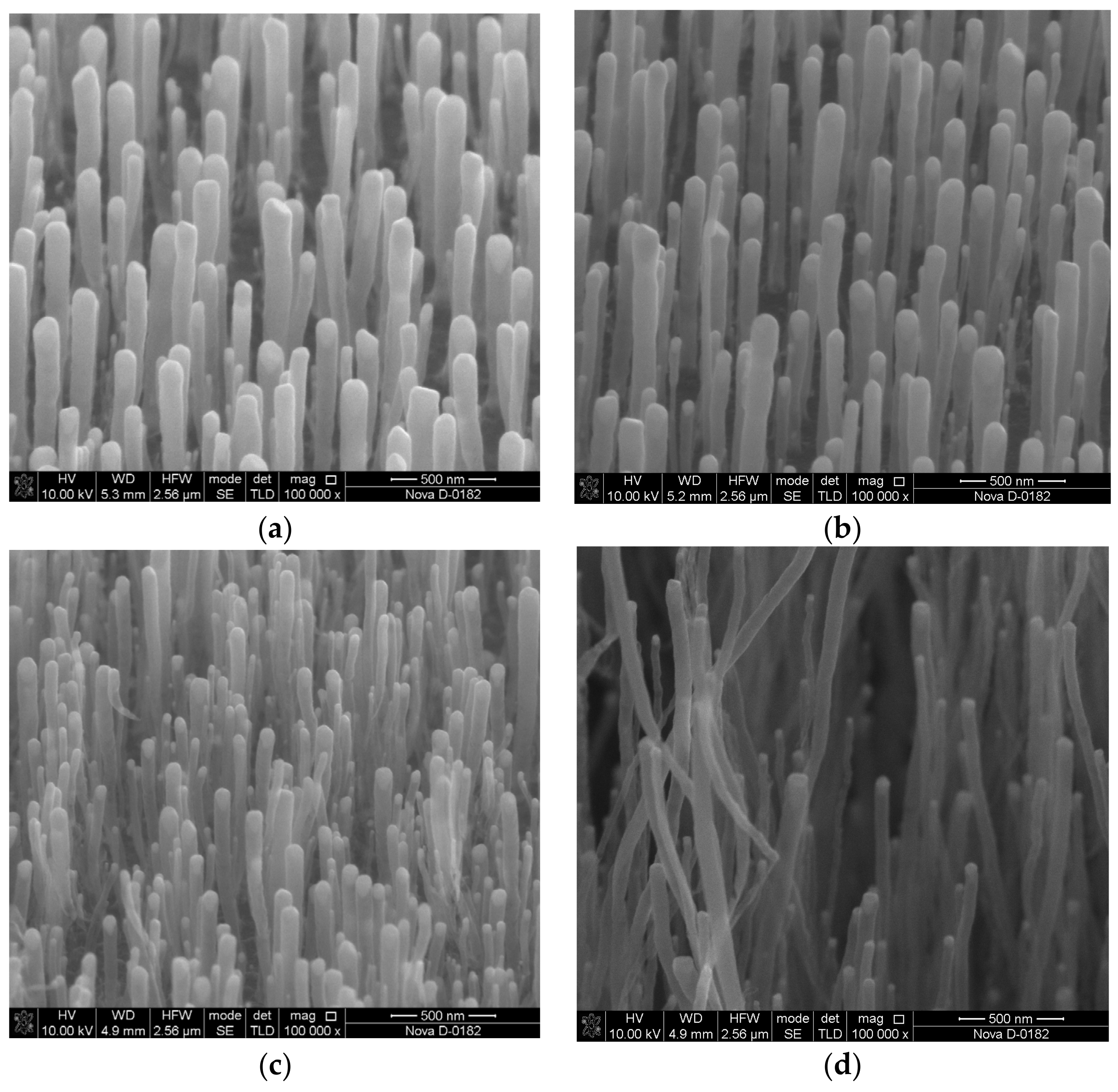
To establish the experimental patterns of the influence of the aspect ratio of the length of a nanotube to its diameter (H) on the piezoelectric properties of N-CNT, a series of samples of vertically aligned CNTs were grown by plasma-enhanced chemical vapor deposition (PECVD). The TiN sublayer 100 nm thick acted as the lower electrode. The thickness of the nickel catalytic layer was 15 nm. The aspect ratio of N-CNTs was controlled by changing the heating time of the nickel catalytic layer from 14 to 20 min in argon (40 cm3/min) and ammonia (15 cm3/min) flows. The effect of heating time (660 °C) on the geometric dimensions of the nickel catalytic centers was described in detail by us earlier in [31]. The variation of this parameter makes it possible to control the geometric parameters of N-CNTs without significant changes in the structure and defectiveness of N-CNTs. Thus, the analysis of the XPS spectra showed that the nitrogen concentration in this series of N-CNT samples was 3.8%. Additionally, the defectiveness of N-CNTs, defined as the ratio of the intensities of the D- and G-modes (ID/IG) of the Raman spectra, was 0.82. At the same time, the results of studying the grown arrays of N-CNTs by scanning electron microscopy (SEM) showed that with an increase in the heating time of the catalytic nickel film from 14 to 20 min, there was a decrease in the diameter of nanotubes from 106 to 66 nm and an increase in the length of the grown nanotubes from 0.8 to 20.7 µm (Figure 1). This pattern was caused by an increase in the rate of surface diffusion of the nickel atoms with an increase in the heating rate of the catalytic nickel film. This fact, in turn, led to the coagulation of small catalytic centers into larger centers and to a subsequent increase in the diameter of nanotubes [31]. In addition, an increase in the diameter of the catalytic centers led to a decrease in their catalytic activity as a result of a decrease in the rate of diffusion of carbon atoms into the catalyst, which also caused a decrease in the length of the grown N-CNTs [31].
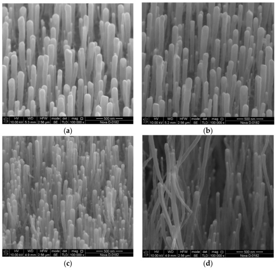
Figure 1.
SEM images of a series of N-CNT samples grown at heating times of the catalytic nickel layer of 14 (a), 16 (b), 18 (c), and 20 (d) minutes.
To characterize the piezoelectric properties of N-CNTs, the piezoelectric strain coefficient, which is one of the main piezoelectric characteristics of the material, was determined. So, the piezoelectric strain coefficient describes the quantitative relationship between electrical induction and mechanical stress for the direct piezoelectric effect, and the relationship between strain and an external electric field for the inverse piezoelectric effect. The piezoelectric strain coefficient d is a rank three tensor, but only the d33 component corresponding to the direction along the nanotube axis was calculated due to the cylindrical symmetry of N-CNTs. In our study, the piezoelectric strain coefficient d33 makes it possible to estimate the magnitude of the curvature-induced polarization [32,33] caused by the bending of the graphene sheet forming a bamboo-like “bridge” in the cavity of N-CNTs. As we have previously established [26,27], the formation of bamboo-like “bridges” is a result of the incorporation of pyrrole-type nitrogen in CNT walls and leads to the anomalous piezoelectric effect in N-CNTs.
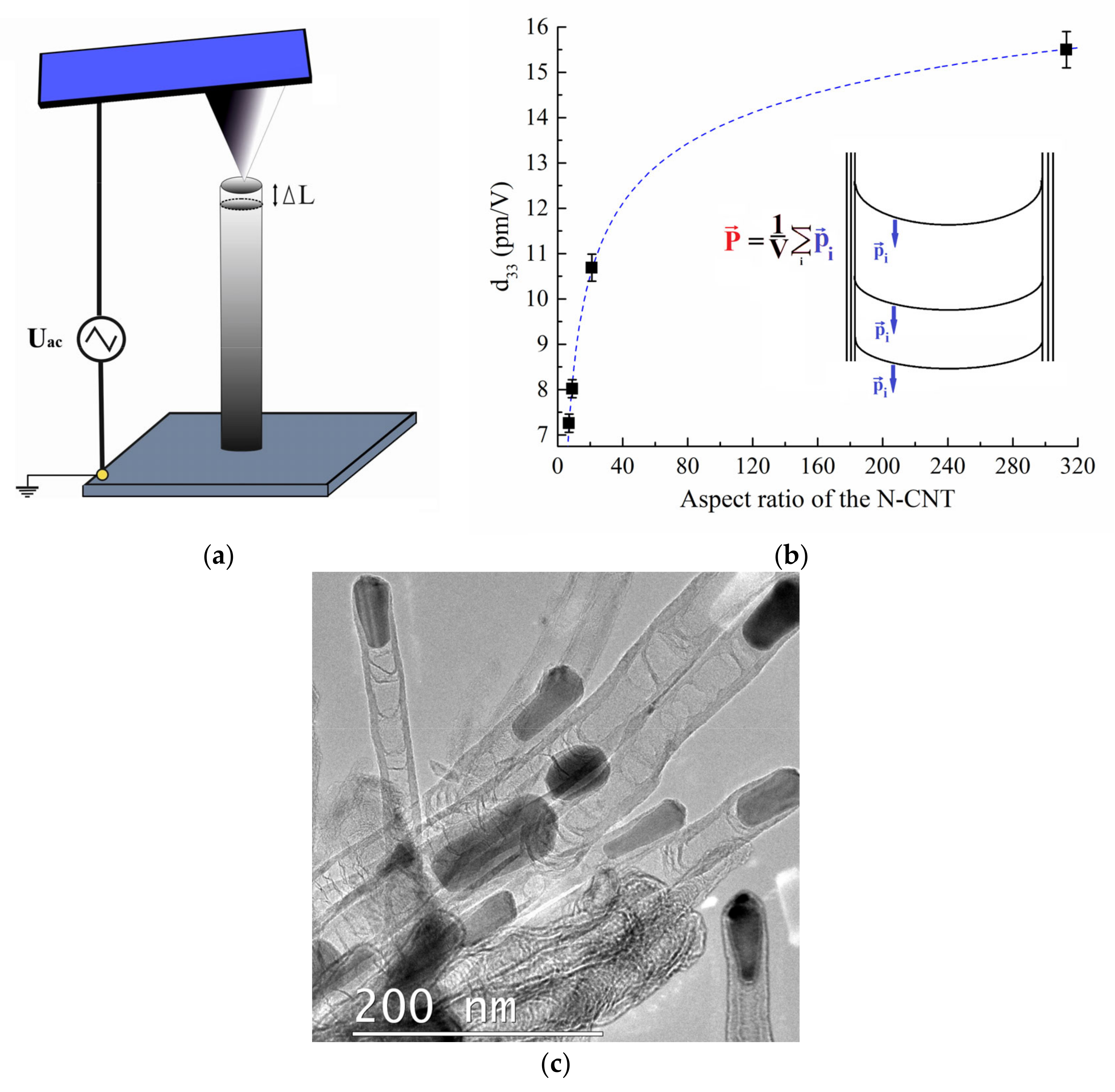
The d33 value was determined as the ratio of the displacement of the atomic force microscopy (AFM) probe as a result of mechanical vibrations of the nanotube to the amplitude of the applied alternating voltage using the piezoresponse force microscopy (PFM) method (Figure 2a). Studies showed that the dependence of the piezoelectric strain coefficient d33 on the aspect ratio H is described by a non-linear logarithmic dependence d33 = 7.7·ln(1.3·ln(H)) (Figure 2b). Thus, the value of d33 increased from 7.3 to 10.7 pm/V with an increase in the aspect ratio from 7 to 21 (which corresponded to an increase in length from 0.8 to 1.3 μm and a decrease in the diameter from 106 to 59 nm). Additionally, then a value d33 reaches 15.6 pm/V with an aspect ratio of 314 (Figure 2c). This dependence is related to the fact that the curvature of the formation a bamboo-like “bridge” graphene sheet increases with a decrease in the diameter of the nanotube, and the dipole moment pi increases proportionally (Figure 2b) [34]. An increase in the length of N-CNTs, on the one hand, leads to an increase in the number of bamboo-like “bridges” and, as a consequence, an increase in the total dipole moment. On the other hand, an increase in length causes an increase in the volume of the nanotube and a decrease in the polarization P, which is the ratio of the sum of pi formed by each “bridge” to its volume (Figure 2b). Figure 2c shows a transmission electron microscopy image of an array of CNTs with bamboo-like «bridges». From the experimental dependence obtained, it can be assumed that when the aspect ratio of CNTs is less than 30, the first process dominates. With a further increase in the aspect ratio, the second process begins to dominate. Thus, it has been shown that the geometric parameters of N-CNTs, along with the nitrogen concentration, affect their piezoelectric properties, which must be taken into account when developing nanopiezotronic devices based on them, such as elements of non-volatile memory [35] and nanogenerators [26,27].
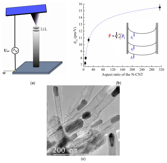
Figure 2.
Study of the N-CNT piezoelectric strain coefficient: (a) measurement scheme; (b) experimental dependence of the piezoelectric strain coefficient on the aspect ratio of the length to diameter of the N-CNT. The inset shows a schematic representation of bamboo-like “bridges” and their corresponding polarization; (c) TEM image of the experimental sample of the N-CNTs.
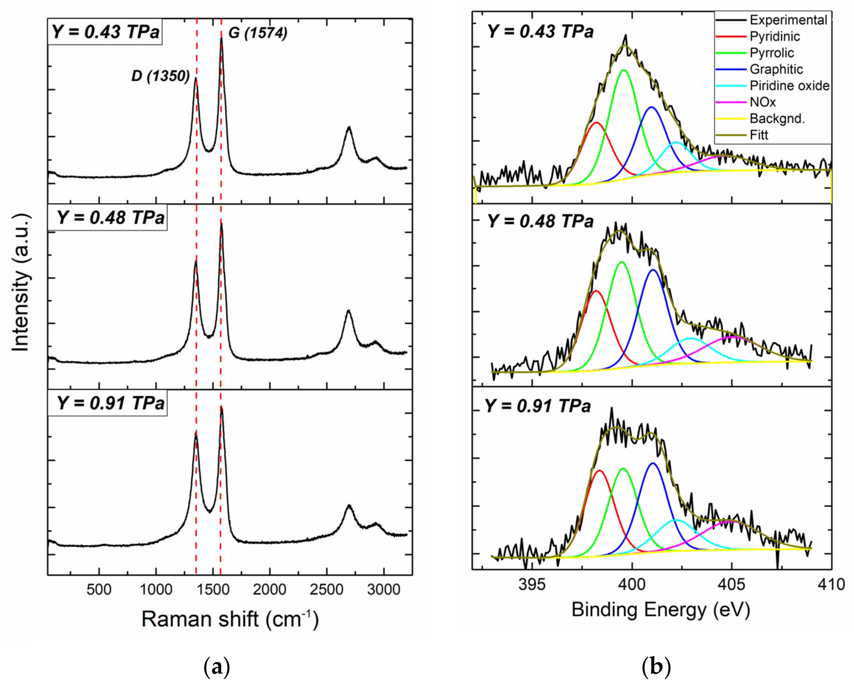
Next, we studied the influence of the mechanical parameters of N-CNTs (Young’s modulus and bending stiffness) on the magnitude of their piezoelectric response. The measurements were performed using a previously developed measurement technique based on the nanoindentation method of atomic force microscopy (AFM) [36], which takes into account the peculiarities of the interaction of the AFM measuring system with vertically aligned nanotubes. Three arrays of N-CNTs grown at a heating time of the nickel catalytic layer for 20 min acted as experimental samples of second series (Figure S1). The thickness of the nickel catalytic layer (from 10 to 20 nm) and the growth temperature (from 660 to 675 °C) were chosen taking into account the need to grow N-CNTs with similar diameters D and lengths L (Table 1). The effect of growth regimes on the geometric parameters of CNTs was previously described in detail in [37]. Similar values of the diameter and the length of the nanotubes made it possible to eliminate the direct effect of the geometric parameters on the value of the N-CNT Young’s modulus. Measurements of experimental samples by nanoindentation showed that the Young’s modulus of N-CNTs varied from 0.43 to 0.91 TPa (Table 1). As further studies by the Raman method showed (Figure 3a), an increase in the Young’s modulus of N-CNTs was associated with an increase in their defectiveness, calculated as an ID/IG ratio from 0.72 to 0.82, respectively (Table 1). An analysis of the XPS spectra showed (Figure 3b) that the increase in N-CNT defectiveness is primarily due to an increase in the concentration of doped nitrogen, in particular, with an increase in pyrrole-type nitrogen (Table 1).

Table 1.
Geometric and structural parameters of the second series of N-CNT samples and the corresponding Young’s modulus.
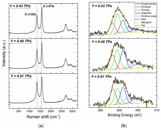
Figure 3.
Spectra of a series of N-CNT samples with different Young’s modulus: (a) RAMAN spectra; (b) high-resolution XPS spectrum of the N1s line.
At the same time, an increase in the Young’s modulus of N-CNTs with an increase in defectiveness is probably caused by an increase in the concentration of pyrrole-type nitrogen (Table 1), which leads to the formation of bamboo-like “bridges” in the cavity of nanotubes. Bamboo-like “bridges”, in turn, increase the stiffness of N-CNTs by analogy with the macroscopic tube, which creates additional resistance to external longitudinal and transverse mechanical impacts. Thus, measurements of N-CNTs by the nanoindentation method confirmed an increase in the stiffness of nanotubes from 0.21 to 0.85 N·m2 with an increase in defectiveness from 0.72 to 0.82.
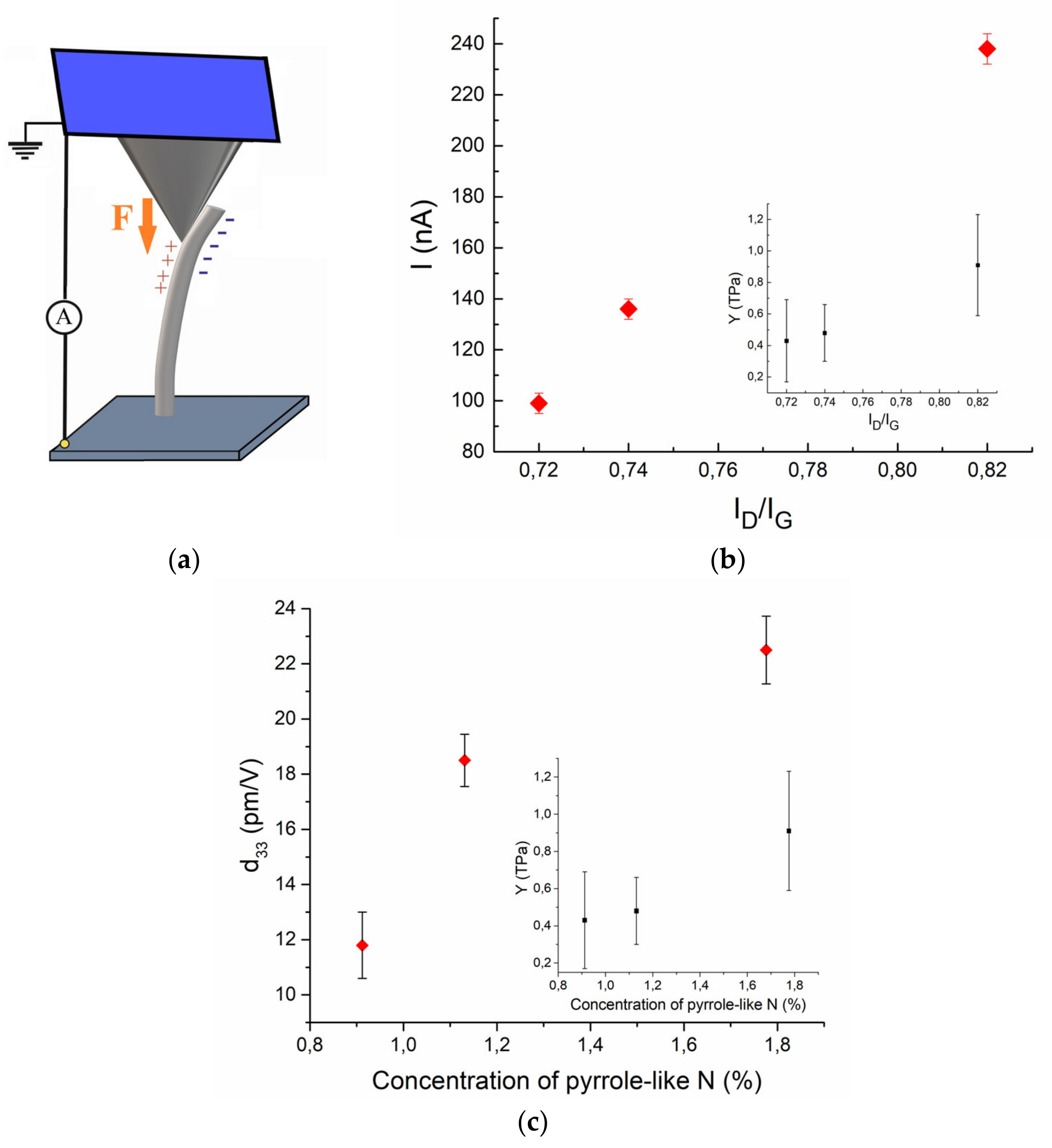
The magnitude of the piezoelectric response, which is the current generated when a force of 3.5 µN is applied to the tip of an N-CNT (Figure 4a), increased from 99 to 238 nA with increasing Young’s modulus from 0.43 to 0.91 TPa (Figure 4b). This dependence, on the one hand, is associated with a proportional increase in the mechanical stress in the N-CNT to its Young’s modulus, and on the other hand with an increase in the piezoelectric strain coefficient of N-CNTs from 11.8 to 22.2 pm/V as a result of an increase in the concentration of pyrrole-type nitrogen. Thus, the incorporation of pyrrole-type nitrogen leads to a simultaneous increase in mechanical and piezoelectric parameters (Figure 4c), which increases the quantity of current generated during N-CNT deformation.
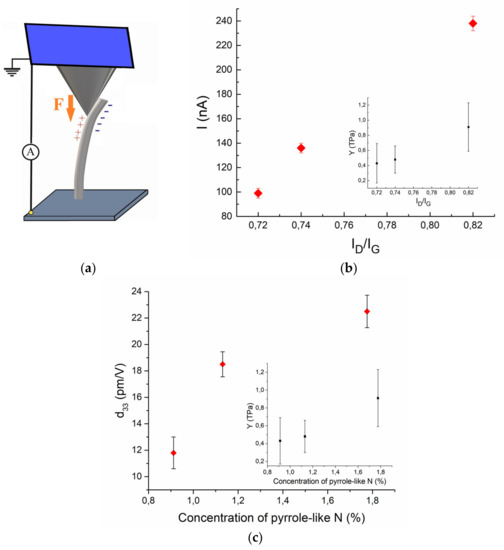
Figure 4.
(a) Schematic representation of the measurement process and (b) experimental dependencies of piezoelectric response and of Young’s modulus (in the inset) on the defectiveness of the N-CNT; (c) experimental dependencies of the piezoelectric strain coefficient and of the Young’s modulus (in the inset) of the N-CNT on the concentration of pyrrole-like nitrogen.
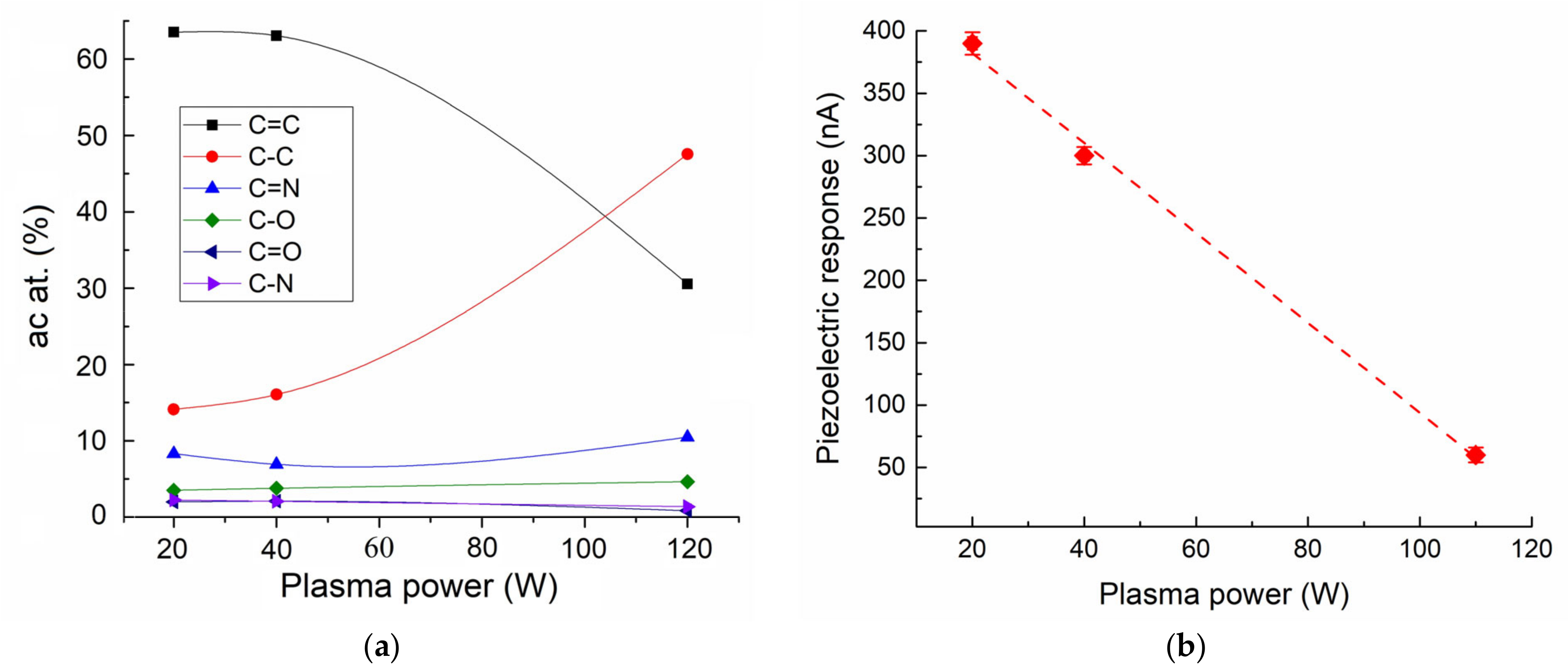
To establish the effect of defectiveness on the piezoelectric properties of nanotubes caused not by the introduction of nitrogen atoms but by the direct destruction of the two-dimensional hexagonal structure of N-CNTs, the third series of N-CNT samples was grown by the PECVD method at a plasma power of 20, 40, and 110 W. As we established earlier, an increase in the plasma power leads to the etching of the nanotube walls by plasma during growth and, as a consequence, to an increase in its defectiveness [37]. The results of the XPS studies showed that an increase in plasma power from 20 to 110 W led to a significant increase in the amount of C-C bond from 14 to 47 at. % with a parallel decrease in C=C bonds, which are responsible for the structural perfection of the nanotube (Figure 5a), which suggests the destruction of its two-dimensional hexagonal structure of the N-CNT. At the same time, the concentration of the carbon bond with oxygen (C-O and C=O) remained at the level of 5.5%, with nitrogen (N-O and N=O) at the level of 10.5% (Figure 5a). The total concentration of the nitrogen dopant also remained constant and amounted to about 4%. In this case, the absolute content of pyrrole-type nitrogen in N-CNTs was 1.1%, 1.2%, and 0.8% for 20, 40, and 110 W, respectively.
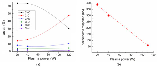
Figure 5.
Relative distribution of carbon bonds in the N-CNT (a) and piezoelectric response of the N-CNT (b) as a function of plasma power of the PECVD method.
The study of N-CNTs of this series of samples by the PFM method showed that the piezoelectric strain coefficient d33 was 14.2 ± 7.2 pm/V, 15.6 ± 8.5 pm/V, and 12.2 ± 0.33 pm/V for plasma powers of 20, 40, and 110 W, respectively. The significant standard deviation of the d33 value for N-CNTs grown at 20 and 40 W power is probably caused by the spread of geometrical parameters of nanotubes in the array (Figure S2). Thus, the change in the piezoelectric strain coefficient of these samples correlated with the change in the concentration of pyrrole-type nitrogen. At the same time, studies of the magnitude of the piezoelectric response showed a linear decrease in the magnitude of the current generated by N-CNTs at a probe pressing force of 15 μN, from 390 to 60 nA with an increase in plasma power from 20 to 110 W, respectively (Figure 5b). This dependence is probably associated with the destruction of the two-dimensional hexagonal structure of the side walls of N-CNTs and a decrease in its conductivity. Thus, we can conclude that structural defects not related to the replacement of carbon atoms by nitrogen atoms do not lead to the manifestation of the piezoelectric response of the nanotube, but, on the contrary, only weaken it.
3. Discussion
The results of experimental studies have shown that the piezoelectric properties of N-CNTs depend not only on the concentration of doped pyrrole-type nitrogen but also on the geometric and mechanical parameters of nanotubes. At the same time, it was found that the concentration of doped nitrogen of the pyrrole type directly affects the defectiveness and mechanical parameters of N-CNTs. Thus, the incorporation of pyrrole-type nitrogen leads to the formation of bamboo-like “bridges”, which, on the one hand, significantly increase the defectiveness of N-CNTs as a result of a significant distortion of the hexagonal lattice of the nanotube; on the other hand, they lead to an increase in the Young’s modulus of N-CNT due to an increase in its stiffness. Thus, with an increase in the concentration of pyrrole-type nitrogen from 24 to 37% of the total concentration of doped nitrogen in N-CNTs, the Id/Ig ratio increases from 0.72 to 0.82, and the value of the Young’s strain coefficient increases from 0.43 to 0.91 TPa. In this case, an increase in the piezoelectric strain coefficient from 11.8 to 22.2 pm/V and an increase in the generated N-CNT current from 99 to 238 nA are observed. Consequently, it can be concluded that the incorporation of pyrrole-type nitrogen leads to a simultaneous increase in the mechanical and piezoelectric parameters, which makes it possible to significantly increase the current generated during N-CNT deformation. At the same time, an increase in the defectiveness of the N-CNT structure, caused by the destruction of the two-dimensional hexagonal structure of the side walls as a result of plasma exposure during growth, leads to a weakening of the piezoelectric response of the N-CNT, probably due to a decrease in the conductivity of the nanotube.
Another important result of the studies performed is the established dependence of the piezoelectric strain coefficient, which characterizes the magnitude of the polarization induced by the curvature of bamboo-like “bridges”, on the geometrical parameters of N-CNTs. As is known, in classical piezoelectrics the value of d33 does not depend on its geometrical parameters. However, in N-CNTs, a decrease in the diameter leads to an increase in the curvature of the surface of the graphene sheet forming a bamboo-like “bridge”, which causes an increase in the electric dipole moment and the piezoelectric strain coefficient, in general. Increasing the length of the nanotube also leads to an increase in the total dipole moment, which is the sum of the electric dipole moments of all “ bridges“. However, an increase in the length of the nanotube simultaneously leads to an increase in the volume of the nanotube, which causes a decrease in the total polarization of the entire N-CNT. Thus, at low values of the aspect ratio of N-CNTs (7–30), a linear increase in d33 is observed, and at high values of the aspect ratio, the dependence becomes non-linear. Still, it should be taken into account that the magnitude of the piezoelectric response, which is the current generated during the deformation of an N-CNT, can decrease with an increase in the nanotube length due to a decrease in its relative deformation under a fixed external load [34].
4. Materials and Methods
Three series of experimental samples of N-CNTs were grown by PECVD on lower electrodes from a TiN film that was 100 nm thick (Table 2). The gas flow ratio of acetylene and ammonia was processed at a ratio of 1:3 (70 and 210 cm3/min, respectively). The temperature T of the first series of growth of samples is 660 °C. The thickness of the nickel catalytic layer h is 15 nm. Plasma power P 40 W. The aspect ratio of N-CNTs was controlled by changing the heating time t of the nickel catalytic layer from 14 to 20 min in argon (40 cm3/min) and ammonia (15 cm3/min) flows. The growth temperature of the second series of samples varied from 660 to 675 °C, and the catalytic thickness of the nickel layer varied from 10 to 20 nm (N-CNT No. 1—675 °C and 20 nm; N-CNT No. 2—675 °C and 10 nm; and N-CNT No. 3—660 °C and 15 nm). The plasma power was 40 W. The heating time of the nickel catalytic layer was 20 min. The growth temperature of the third series of samples of the totality was 660 °C. The thickness of the nickel catalytic layer was 15 nm. The heating time of the nickel catalytic layer was 20 min. The plasma power varied from 20 to 110 W.

Table 2.
Growth parameters of the N-CNT samples.
The characterization of the experimental samples was carried out using scanning electron microscopy (SEM) using Nova NanoLab 600 (FEI, Eindhoven, Netherlands), the Raman scattering (RS) method using Renishaw InVia Reflex (Renishaw plc, Wotton-under-Edge, UK) with laser excitation wave-lengths of 514.5 nm, and X-ray photoelectron spectroscopy (XPS) using the K-Alpha setup with a monochromatic X-ray source Al Kα (hν = 1486.6 eV) (ThermoScientific, Waltham, MA, USA).
The piezoelectric response of N-CNTs was studied using a previously developed proprietary technique based on the method of force spectroscopy of atomic force microscopy at the Ntegra probe nanolaboratory (PNL) (NT-MDT, Moscow, Russia). This technique makes it possible to detect the electric current that arises in the “bottom electrode/N-CNT/AFM probe” system during the deformation of aligned carbon nanotubes under the action of a controlled mechanical action of the AFM probe on its tops (Figure 2a). The value of the external force applied to the AFM probe was 5 µN. The conductive TiN sublayer acted as the lower electrode. The current flowed as a result of the formation of a surface potential on the deformed N-CNTs when the upper electrode was connected, which was grounded. The top electrode was an NSG10 probe with a conductive TiN coating.
The value of the piezoelectric strain coefficient of N-CNTs was determined by piezoelectric force microscopy using Ntegra PNL. The value of the piezoelectric strain coefficient of N-CNT d33 was determined as the ratio of the displacement of the AFM probe as a result of mechanical vibrations of the nanotube to the amplitude of the applied alternating voltage U = UDC + UAC(sin(φt)) with UDC of ±10 V, UAC of ±3.0 V, and φ of 5 kHz (Figure 4a). The proportionality factor that relates the measured vibration amplitude in nA to the surface displacement in pm was pre-calibrated for this PFM measurement system and was equal to 18.8 pm/nA.
5. Conclusions
Thus, the piezoelectric properties of N-CNTs are complex characteristics that take into account the totality of structural, mechanical, and geometrical parameters of nanotubes. To develop energy-efficient PENGs, it is necessary to achieve the maximum value of the piezoelectric response of N-CNTs, which depends on the concentration of pyrrole-like nitrogen, which determines the value of the piezoelectric strain coefficient, on the mechanical parameters and on the structural perfection of the side walls. In this case, it is necessary to take into account the dependence of the piezoelectric response and the piezoelectric strain coefficient of N-CNTs on the geometric parameters. Thus, it is expedient to use arrays of N-CNTs with an aspect ratio of about 30 in order to achieve a high value of the piezoelectric strain coefficient and maintain a high “sensitivity” of N-CNTs to external mechanical load. The “sensitivity” of N-CNTs to external mechanical load achieved in this study is about 50 nA/µN. In this case, the value of the surface potential of N-CNTs under a similar mechanical action reaches hundreds of mV [26]. Thus, the power of a nanogenerator based on single N-CNTs reaches tens of nW. In this case, the power can be increased hundreds to thousands of times by increasing the value of the output current by increasing the number of N-CNTs interacting with the upper electrode. For comparison, the output power of PENG on ZnO nanowires is about 1 pW (1.2 nA and 0.08 V) [38], and for modern triboelectric nanogenerators on CNTs it is about 672 nW (0.21 μA and 3.2 V) [39,40]. At the moment, we are working in this direction in order to create a prototype of a piezoelectric nanogenerator based on an array of N-CNTs.
Supplementary Materials
The following supporting information can be downloaded at https://www.mdpi.com/article/10.3390/jlpea13010011/s1, Figure S1: SEM images of the experimental samples of the N-CNTs of the second series; Figure S2: SEM images of the experimental samples of the N-CNTs of the third series.
Author Contributions
Conceptualization, M.V.I. and O.I.I.; investigation, performance of the AFM and PFM experiments, O.I.S.; investigation, performance of the XPS experiments, S.A.K.; resources, growth of the N-CNTs by the PECVD, O.I.I.; formal analysis and project administration, V.A.S. and M.V.I.; writing—original draft preparation, M.V.I.; and supervision, M.V.I. All authors have read and agreed to the published version of the manuscript.
Funding
The reported studies were funded by the Russian Science Foundation grant No. 22-79-10163 at the Southern Federal University and by the Russian Federation Government (Agreement No. 075-15-2022-1123). The growth of a second series of samples, the study of the piezoelectric strain coefficient, and the XPS measurements of N-CNT were carried out within the framework of the project No. 22-79-10163. The growth of the third series of samples; the RAMAN measurements; the determination of the mechanical parameters; and the piezoelectric response of N-CNTs were carried out within the framework of the project No. 075-15-2022-1123.
Data Availability Statement
Not applicable.
Conflicts of Interest
The authors declare no conflict of interest.
References
- Mahapatra, S.D.; Mohapatra, P.C.; Aria, A.I.; Christie, G.; Mishra, Y.K.; Hofmann, S.; Thakur, V.K. Piezoelectric Materials for Energy Harvesting and Sensing Applications: Roadmap for Future Smart Materials. Adv. Sci. 2021, 8. [Google Scholar] [CrossRef]
- Gogurla, N.; Kim, S. Self-Powered and Imperceptible Electronic Tattoos Based on Silk Protein Nanofiber and Carbon Nanotubes for Human–Machine Interfaces. Adv. Energy Mater. 2021, 11, 2100801. [Google Scholar] [CrossRef]
- Sun, W.; Gao, B.; Chi, M.; Xia, Q.; Yang, J.J.; Qian, H.; Wu, H. Understanding memristive switching via in situ characterization and device modeling. Nat. Commun. 2019, 10, 3453. [Google Scholar] [CrossRef] [PubMed]
- Sahu, D.P.; Jetty, P.; Jammalamadaka, S.N. Graphene oxide based synaptic memristor device for neuromorphic computing. Nanotechnology 2021, 32, 155701. [Google Scholar] [CrossRef]
- Zhang, J.; Wang, C.; Bowen, C. Piezoelectric effects and electromechanical theories at the nanoscale. Nanoscale 2014, 6, 13314–13327. [Google Scholar] [CrossRef] [PubMed]
- Zhang, Y.; Liu, Y.; Wang, Z.L. Fundamental theory of piezotronics. Adv. Mater. 2011, 23, 3004–3013. [Google Scholar] [CrossRef]
- Wang, Z.L.; Song, J. Piezoelectric Nanogenerators Based on Zinc Oxide Nanowire Arrays. Science 2006, 312, 242–246. [Google Scholar] [CrossRef]
- Gao, P.X.; Song, J.; Liu, J.; Wang, Z.L. Nanowire piezoelectric nanogenerators on plastic substrates as flexible power sources for nanodevices. Adv. Mater. 2007, 19, 67–72. [Google Scholar] [CrossRef]
- Hu, D.; Yao, M.; Fan, Y.; Ma, C.; Fan, M.; Liu, M. Strategies to achieve high performance piezoelectric nanogenerators. Nano Energy 2019, 55, 288–304. [Google Scholar] [CrossRef]
- Xu, S.; Hansen, B.J.; Wang, Z.L. Piezoelectric-nanowire-enabled power source for driving wireless microelectronics. Nat. Commun. 2010, 1, 93. [Google Scholar] [CrossRef]
- Han, J.K.; Jeon, D.H.; Cho, S.Y.; Kang, S.W.; Yang, S.A.; Bu, S.D.; Myung, S.; Lim, J.; Choi, M.; Lee, M.; et al. Nanogenerators consisting of direct-grown piezoelectrics on multi-walled carbon nanotubes using flexoelectric effects. Sci. Rep. 2016, 6, 29562. [Google Scholar] [CrossRef]
- Shin, S.H.; Kim, Y.H.; Jung, J.Y.; Hyung Lee, M.; Nah, J. Solvent-assisted optimal BaTiO3 nanoparticles-polymer composite cluster formation for high performance piezoelectric nanogenerators. Nanotechnology 2014, 25, 485401. [Google Scholar] [CrossRef]
- Chandratre, S.; Sharma, P. Coaxing graphene to be piezoelectric. Appl. Phys. Lett. 2012, 100, 15–17. [Google Scholar] [CrossRef]
- Javvaji, B.; He, B.; Zhuang, X. The generation of piezoelectricity and flexoelectricity in graphene by breaking the materials symmetries. Nanotechnology 2018, 29, 225702. [Google Scholar] [CrossRef] [PubMed]
- Bistoni, O.; Barone, P.; Cappelluti, E.; Benfatto, L.; Mauri, F. Giant effective charges and piezoelectricity in gapped graphene. 2D Mater. 2019, 6, 045015. [Google Scholar] [CrossRef]
- Wang, X.; Tian, H.; Xie, W.; Shu, Y.; Mi, W.-T.; Ali Mohammad, M.; Xie, Q.-Y.; Yang, Y.; Xu, J.-B.; Ren, T.-L. Observation of a giant two-dimensional band-piezoelectric effect on biaxial-strained graphene. NPG Asia Mater. 2015, 7, e154. [Google Scholar] [CrossRef]
- Duggen, L.; Willatzen, M.; Wang, Z.L. Mechanically Bent Graphene as an Effective Piezoelectric Nanogenerator. J. Phys. Chem. C 2018, 122, 20581–20588. [Google Scholar] [CrossRef]
- Ong, M.T.; Reed, E.J. Engineered Piezoelectricity in Graphene. ACS Nano 2012, 6, 1387–1394. [Google Scholar] [CrossRef] [PubMed]
- Ong, M.T.; Duerloo, K.A.N.; Reed, E.J. The effect of hydrogen and fluorine coadsorption on the piezoelectric properties of graphene. J. Phys. Chem. C 2013, 117, 3615–3620. [Google Scholar] [CrossRef]
- El-Kelany, K.E.; Carbonnière, P.; Erba, A.; Sotiropoulos, J.-M.; Rérat, M. Piezoelectricity of Functionalized Graphene: A Quantum-Mechanical Rationalization. J. Phys. Chem. C 2016, 120, 7795–7803. [Google Scholar] [CrossRef]
- da Cunha Rodrigues, G.; Zelenovskiy, P.; Romanyuk, K.; Luchkin, S.; Kopelevich, Y.; Kholkin, A. Strong piezoelectricity in single-layer graphene deposited on SiO2 grating substrates. Nat. Commun. 2015, 6, 7572. [Google Scholar] [CrossRef] [PubMed]
- Yang, Y.; Tian, H.; Sun, H.; Xu, R.-J.; Shu, Y.; Ren, T.-L. A Spring-Connected Nanogenerator Based on ZnO Nanoparticles and Multiwall Carbon Nanotube. RSC Adv. 2013, 4, 2115–2118. [Google Scholar] [CrossRef]
- Hu, C.J.; Lin, Y.H.; Tang, C.W.; Tsai, M.Y.; Hsu, W.K.; Kuo, H.F. ZnO-coated carbon nanotubes: Flexible piezoelectric generators. Adv. Mater. 2011, 23, 2941–2945. [Google Scholar] [CrossRef] [PubMed]
- Sun, H.; Tian, H.; Yang, Y.; Xie, D.; Zhang, Y.-C.; Liu, X.; Ma, S.; Zhao, H.-M.; Ren, T.-L. A novel flexible nanogenerator made of ZnO nanoparticles and multiwall carbon nanotube. Nanoscale 2013, 5, 6117. [Google Scholar] [CrossRef]
- Zhang, J.; Wang, R.; Wang, C. Piezoelectric ZnO-CNT nanotubes under axial strain and electrical voltage. Phys. E Low-Dimens. Syst. Nanostructures 2012, 46, 105–112. [Google Scholar] [CrossRef]
- Il’ina, M.; Il’in, O.; Osotova, O.; Khubezhov, S.; Rudyk, N.; Pankov, I.; Fedotov, A.; Ageev, O. Pyrrole-like defects as origin of piezoelectric effect in nitrogen-doped carbon nanotubes. Carbon 2022, 190, 348–358. [Google Scholar] [CrossRef]
- Il’ina, M.V.; Osotova, O.I.; Rudyk, N.N.; Khubezhov, S.A.; Pankov, I.V.; Ageev, O.A.; Il’in, O.I. Sublayer material as a critical factor of piezoelectric response in nitrogen-doped carbon nanotubes. Diam. Relat. Mater. 2022, 126, 109069. [Google Scholar] [CrossRef]
- Arenal, R.; March, K.; Ewels, C.P.; Rocquefelte, X.; Kociak, M.; Loiseau, A.; Stéphan, O. Atomic Configuration of Nitrogen-Doped Single-Walled Carbon Nanotubes. Nano Lett. 2014, 14, 5509–5516. [Google Scholar] [CrossRef]
- Louchev, O.A. Formation mechanism of pentagonal defects and bamboo-like structures in carbon nanotube growth mediated by surface diffusion. Phys. Status Solidi Appl. Res. 2002, 193, 585–596. [Google Scholar] [CrossRef]
- Sumpter, B.G.; Meunier, V.; Romo-Herrera, J.M.; Cruz-Silva, E.; Cullen, D.A.; Terrones, H.; Smith, D.J.; Terrones, M. Nitrogen-mediated carbon nanotube growth: Diameter reduction, metallicity, bundle dispersability, and bamboo-like structure formation. ACS Nano 2007, 1, 369–375. [Google Scholar] [CrossRef]
- Il’in, O.; Rudyk, N.; Fedotov, A.; Il’ina, M.; Cherednichenko, D.; Ageev, O. Modeling of Catalytic Centers Formation Processes during Annealing of Multilayer Nanosized Metal Films for Carbon Nanotubes Growth. Nanomaterials 2020, 10, 554. [Google Scholar] [CrossRef] [PubMed]
- Dumitrica, T.; Landis, C.M.; Yakobson, B.I. Curvature-induced polarization in carbon nanoshells. Chem. Phys. Lett. 2002, 360, 182–188. [Google Scholar] [CrossRef]
- Kundalwal, S.I.; Meguid, S.A.; Weng, G.J. Strain gradient polarization in graphene. Carbon 2017, 117, 462–472. [Google Scholar] [CrossRef]
- Il’ina, M.V.; Soboleva, O.I.; Rudyk, N.N.; Polyvianova, M.R.; Khubezhov, S.A.; Il’in, O.I. Influence of the aspect ratio of nitrogen-doped carbon nanotubes on their piezoelectric properties. J. Adv. Dielectr. 2022, 12, 2241001. [Google Scholar] [CrossRef]
- Il’ina, M.V.; Il’in, O.I.; Osotova, O.I.; Smirnov, V.A.; Ageev, O.A. Memristors based on strained multi-walled carbon nanotubes. Diam. Relat. Mater. 2022, 123, 108858. [Google Scholar] [CrossRef]
- Ageev, O.A.; Il’in, O.I.; Kolomiitsev, A.S.; Konoplev, B.G.; Rubashkina, M.V.; Smirnov, V.A.; Fedotov, A.A. Development of a technique for determining Young’s modulus of vertically aligned carbon nanotubes using the nanoindentation method. Nanotechnologies Russ. 2012, 7, 47–53. [Google Scholar] [CrossRef]
- Il’in, O.I.; Il’ina, M.V.; Rudyk, N.N.; Fedotov, A.A.; Ageev, O.A. Vertically Aligned Carbon Nanotubes Production by PECVD. In Perspective of Carbon Nanotubes; IntechOpen: London, UK, 2019; Volume i, p. 13. ISBN 9781634858045. [Google Scholar]
- Wang, L.; Yang, C.; Wen, J.; Gai, S.; Peng, Y. Electrical properties and applications of carbon nanotube structures. J. Mater. Sci. Mater. Electron. 2015, 26, 4618–4628. [Google Scholar] [CrossRef]
- Oguntoye, M.; Johnson, M.; Pratt, L.; Pesika, N.S. Triboelectricity Generation from Vertically Aligned Carbon Nanotube Arrays. ACS Appl. Mater. Interfaces 2016, 8, 27454–27457. [Google Scholar] [CrossRef]
- Khan, S.A.; Zhang, H.L.; Xie, Y.; Gao, M.; Shah, M.A.; Qadir, A.; Lin, Y. Flexible Triboelectric Nanogenerator Based on Carbon Nanotubes for Self-Powered Weighing. Adv. Eng. Mater. 2017, 19, 1600710. [Google Scholar] [CrossRef]
Disclaimer/Publisher’s Note: The statements, opinions and data contained in all publications are solely those of the individual author(s) and contributor(s) and not of MDPI and/or the editor(s). MDPI and/or the editor(s) disclaim responsibility for any injury to people or property resulting from any ideas, methods, instructions or products referred to in the content. |
© 2023 by the authors. Licensee MDPI, Basel, Switzerland. This article is an open access article distributed under the terms and conditions of the Creative Commons Attribution (CC BY) license (https://creativecommons.org/licenses/by/4.0/).

