Abstract
Machine-learning accelerators rely on floating-point matrix and vector multiplication kernels. To reduce their cost, customized many-term fused architectures are preferred, which improve the latency, power, and area of the designs. In this work, we design a parameterized fused many-term floating-point dot product architecture that is ready for high-level synthesis. In this way, we can exploit the efficiency offered by a well-structured fused dot-product architecture and the freedom offered by high-level synthesis in tuning the design’s pipeline to the selected floating-point format and architectural constraints. When compared with optimized dot-product units implemented directly in RTL, the proposed design offers lower-latency implementations under the same clock frequency with marginal area savings. This result holds for a variety of floating-point formats, including standard and reduced-precision representations.
1. Introduction
Deep learning algorithms are ubiquitous in multiple application domains [1]. This trend has led to increased interest in accelerating them directly in hardware [2,3]. Most deep learning algorithms rely heavily on matrix and vector operations, both for training and for inference. To achieve the required dynamic range and numerical accuracy, training is performed mostly in Floating-Point (FP) arithmetic [2]. Inference, on the other hand, can be performed either in FP, or with integer arithmetic after data quantization [4].
The IEEE-754 single- and double-precision formats are widely used in general-purpose computations. To achieve lower-cost implementations when employing FP arithmetic, the designers need to achieve a balance between numerical performance and cost. For deep-learning applications, it suffices to use reduced-precision FP arithmetic that uses 16 or fewer bits in total, in an effort to balance numerical performance and cost [5,6,7]. For instance, the new 8-bit FP format [8] that was introduced recently by NVIDIA, Intel, and ARM exhibits adequate performance for the training and inference tasks of mainstream CNN models. Figure 1 depicts the formats of standard 32-bit floats, 16-bit Bfloats, and the two 8-bit wide variants. Reduced precision representations lose some of the accuracy of single-precision floats, but they approach the hardware cost of integer implementations [2,9].
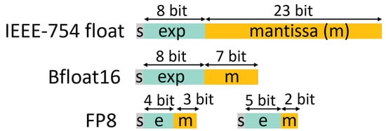
Figure 1.
The structure of the most commonly used and recently proposed FP formats.
To reduce the inherent overhead of FP arithmetic when implementing vector-wide operations, such as dot products, designers have turned to fusing individual FP operations to more complex ones that implement the needed computation at once [10,11,12,13,14]. In this way, alignment, normalization, and rounding steps can be shared across independent operations, thereby leading to more efficient hardware architectures. State-of-the-art fused vector FP dot product architectures rely on fixed pipeline organizations designed directly in RTL. Any parameterization within these designs solely facilitates the resizing of certain blocks, based on the structure of the selected FP format.
Every FP number consists of three fields: the sign bit (s), the exponent (e), and the mantissa (m). The value of the FP number is given as 1 m × . The bias is a fixed value that depends on the bit-width of the exponent. The mantissa, combined with a hidden bit, forms the normalized fraction of the FP number that is equal to 1 m. Corner cases, such as not-a-number, infinity, or de-normals are also appropriately encoded in every representation. In most deep-learning hardware operators, de-normals are flushed to zero for maximum efficiency [5,7].
Another approach to simplifying the implementation of FP operators is to allow wider precision for the output result than the precision of the inputs [15,16], i.e., operating on two FP8 operands and presenting the result as a 16-bit FP. In this way, rounding may be redundant and the overall hardware cost is reduced.
In this work, our goal is twofold. On one hand, we leverage the state-of-the-art fused dot-product architectures, such as [11,13,14], by modelling them in C++ and synthesizing then in RTL using High-Level Synthesis (HLS). Thus, the parameterized design allows for compile-time selection of exponent and mantissa widths, as well as vector sizes. On the other hand, we go beyond those designs’ fixed-pipeline structure and let HLS optimize their internal pipeline structure on a per-application basis by appropriately altering the examined architectural constraints.
Even though all commercial and academic HLS FP libraries [17,18,19,20] can synthesize a vector dot product using efficient primitive FP multiply and add operators, none of them – to the best of our knowledge – supports fused dot product computation, thus paying the price of alignment, normalization, and rounding per FP operation.
Overall, the contributions of this work can be summarized as follows:
- A templatized fused vector FP dot product C++ model is presented, which brings the efficiency of fused FP architectures to High Level Synthesis for the first time, allowing the design of efficient and customized architectures.
- The design is open-sourced as part of the FastFloat4HLS library [21] that allows the definition of templatized FP datatypes and primitive operators built on top of the publicly available ac_int library for integer arithmetic [17].
- Experimental results demonstrate that the proposed designs lead to area and latency savings at the same clock frequency target. For 32-bit standard floats, this benefit comes with a power increase, while for reduced precision 16-bit bfloats [5], power is, in fact, reduced with the proposed architecture.
The rest of this paper is organized as follows: Section 2 describes the architecture of the proposed fused vector dot product architecture and its usage in HLS C++ models. Section 3 compares the proposed architecture with state-of-the-art vector dot product for ASIC implementations. Conclusions are drawn in Section 4.
2. Fused Vector Dot Product for HLS
The proposed fused dot product operator is applied on arbitrary-precision floating point datatypes defined in the FastFloat4HLS C++ library developed in house [21]. The corresponding datatypes are defined as fast_float<M, E>, where constants M and E refer to the size of the mantissa and the exponent fields, respectively. Single-precision floats correspond to fast_float<23, 8>, while bfloat16 is equivalent to fast_float<7, 8>. FastFloat4HLS contains type-cast functions that allow the conversion from standard C++ floating point datatypes to fast_float. Also, similar to all other FP libraries available for HLS [17,18,19], FastFloat4HLS implements primitive arithmetic operators, allowing the designer to implement any algorithm in hardware using typical C++ behavior modeling.
2.1. Using the Dot Product in C++
The differentiating characteristic of FastFloat4HLS relative to other FP libraries is the implementation of an efficient fused dot product operator through the templatized function dot that is defined as follows:


The function accepts two vectors a and b of N elements each and computes in a fully parallel approach
The only constraint is that the elements of a and b should follow the same fast_float configuration.
Synthesizing the dot product from primitive FP multipliers and adders would limit the expected gains due to the high latency, area, and energy cost for alignment, normalization, and rounding in each step [18,22]. On the contrary, a fused architecture mitigates these overheads to a single alignment, normalization, and rounding step [14].
The proposed dot product operator can be used in the context of HLS to implement more complex operations. For instance, Figure 2 depicts the implementation of a matrix × vector multiplication, where the matrix A is multiplied with vector V using the proposed vector dot product unit.

Figure 2.
An implementation of a matrix-vector multiplication using the dot product operator of Fast-Float4HLS.
2.2. Architecture of the Fused FP Dot Product
The fused computation of the dot product follows a tree structure that is split in four consecutive steps, as depicted in Figure 3. This computation pattern may imply that the hardware organization follows the same four-level fixed-pipeline structure. However, the actual pipeline is determined automatically by HLS, based on the designer’s constraints. For, instance, we can get area-efficient single-cycle designs, or high-speed pipelined implementations, without altering the C++ hardware model. Implementing the dot-product with a chain of multiply-add units is not preferred as it leads to inferior designs according to [23].
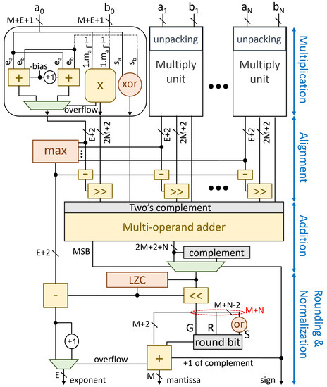
Figure 3.
The unrolled architecture of the fused many-term dot product unit modeled for HLS. The organization resembles other fixed-pipeline organizations, such as these architectures [13,14].
The N pairs of FP inputs are first unpacked, creating the fraction of each operand by inserting the hidden bit to the mantissa, before being forwarded to the multiplication units. Since we target deep-learning accelerators de-normals at the input are flushed to zero [7].
2.2.1. Multiplication of Fractions
Each multiplication unit computes the product of the two fractions 1 and 1 and adds their exponents. The product of the two fractions is computed using an integer unsigned multiplier. The product is positive when the two inputs have equal signs, and negative otherwise.
The sum of the two exponents is computed in parallel to the multiplication. Since the exponent of each operand also contains its bias, the sum of two exponents would result in adding the bias twice, i.e., . For the result to follow the correct representation, one constant bias should be removed. Thus, the exponent of the product is calculated as .
This result is correct unless the multiplication operation overflows. Each FP number represents a value in the range [1,2). This means that by multiplying two numbers, the range of the product will be [1,4). As a normalized value is always in the range [1,2), a result that is greater than, or equal to, 2 is denoted as an overflow and needs to be re-normalized. For example, when multiplying the result of the multiplication is , which is greater than 2. To normalize the product, the fraction should be shifted to the right by one position, while the exponent should be increased by 1. Since we do not want this correction of the exponents to be performed after the multiplication, we pre-compute speculatively the overflowed value for the exponents in parallel to the multiplication. Based on the outcome of the multiplication (i.e., if the product is larger than 2), the normal of the overflowed exponent value is selected.
Figure 4 depicts a snippet of the C++ model that describes the functionality of the multiplication unit. The hls_unroll pragma guides the HLS tool to generate N parallel instances, equal to the amount of individual multiplications that are defined by the template parameter N. The two versions of the exponent and the multiplication of the two fractions are computed in parallel, as all three operations are independent to each other. The correct exponent is selected depending on the value of the product, when this becomes available.

Figure 4.
A snippet of the C++ description that implements the N parallel multiplication units.
2.2.2. Alignment of Products
Each multiplication unit produces the product of the corresponding fractions and the sum of their exponents. To add these intermediate results, we first need to align them, since each one is associated with a different exponent.
To perform the necessary alignment, we need to find the maximum of the N exponents and then right-shift the fraction of each operand so that their exponents become equal to the maximum. Each right shift on the fraction equals to an increase by 1 in the exponent, meaning that each operand should be right-shifted as many times as the difference between the corresponding exponent and the maximum one. To compute the difference between the maximum exponent and the exponent of each part, the maximum exponent value is forwarded to all subtraction units, where the amount of shifting for each individual fraction is calculated.
To design a tree-based max function that finds the maximum exponent of the N intermediate exponents, a recursive template meta-programming [24] approach was adopted, as recommended in [25] and shown in Figure 5. In each iteration of the recursion, the function searches for the maximum value in each half of the input vector.
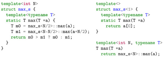
Figure 5.
A recursive template meta-programming approach for the design of a maximum-element identification hardware unit with logarithmic depth.
2.2.3. Addition
After alignment, we need to transform each pair of (sign, unsigned fraction) to its appropriate signed representation, in order to add them with the remaining fractions. After this transformation, the N product fractions are reduced to one using an N-to-1 addition tree, which is generated through the C++ code depicted in Figure 6.

Figure 6.
The C++ description that generates the addition tree by adding the positive or the negative value of the intermediate shifted product, depending on its sign.
State-of-the-art designs [12,13,14,23] utilize carry-save adders to implementing this multi-operand addition. Since we are working at the C++ level, this is not a preferred choice. In our case, multi-operand addition is abstractly represented as an unrolled reduction C++ loop. Even with this abstract form, this approach does not limit the efficiency of the final hardware, since carry-save arithmetic will be enabled after all post-HLS processes by the bit-level transformations of the RTL logic synthesis tool.
If the result of the multi-operand adder is negative, we need to compute its absolute value. To do so, we need to complement the output of the multi-operand adder and increment it by 1. To save delay, we postpone the +1 increment for the rounding step. Therefore, the value that is forwarded to the rounding and normalization stage is selected between the original and the inverted version of the output of the multi-operand addition, depending on the sign of this output.
2.2.4. Normalization and Rounding
At the end, the result of the dot product should be normalized and rounded. To complete normalization, we need to count the number of leading zeros of the fraction, and then shift the fraction to the left as many positions as the number of leading zeros. In parallel, the computed Leading Zero Count (LZC) should be subtracted from the exponent.
Leading-zero counting implements in C++ the fast design proposed in [26], using recursive templates, as depicted in Figure 7a. In this way, LZC is not treated as a monolithic block, but it can be scheduled in a fine-grained manner along with the exponent update and mantissa alignment.
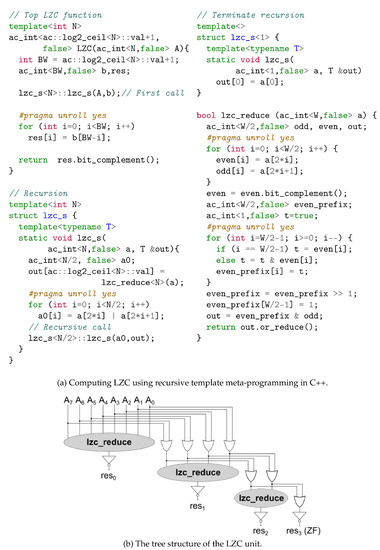
Figure 7.
The C++ model of the Leading Zero Count unit (a) and its structure (b).
The operation initiates through the top LZC function, which receives the input A and starts the recursion by calling the lzc_s function. In each recursive step of lcz_s, lzc_reduce decides if the number of leading zeros is an odd, or even number. Initially, lzc_reduce is applied to the whole input and, in each one of the following steps, the input is reduced to half by computing the logic OR of neighbor bits. When only one bit remains, the recursion stops. If the input is the all-zero vector from the beginning, flag ZF is asserted. In this case, this implementation [26] treats the remaining bits of the leading-zero count as “don’t care”. Otherwise, the complementary value of the inverted sequence of the intermediate results, which gets returned by the top function LZC at the end of the operation, indicates the number of leading zeros in A.
The recursive template, combined with the unrolled loops in the C++ code, lead to the tree structure of the LZC unit, which is illustrated in Figure 7b. The input is fed at the top level of the structure, where the first output is generated form the lzc_reduction unit, and, as it moves to the next level, its size is reduced to half, until a single bit remains. At each level, the produced output is inverted before its value is used.
The least significant bits of the normalized fraction are used to compute the round bit that will be added to the LSB of the most significant bits. If the result of the addition was negative and the output was inverted, then the increment by 1 that was postponed from the addition step is also performed. As a single-bit value, this addition does not require an extra addition unit, but, instead, the value is pushed to the carry-in bit of the already existing adder. In the case that rounding overflows, the exponent is increased by 1 and the fraction is shifted right by one position.
At the end, the E less significant bits of the exponent, the M less significant bits of the fraction and the sign bit that was produced by the MSB of the multi-operand addition are packed and pushed to the output.
3. Evaluation
The C++ model of the proposed FP many-term dot product unit was thoroughly tested through C++ simulation to ensure its correct functionality. Subsequently, the verified designs were synthesized with Catapult HLS after setting the appropriate architectural constraints. Our goal was to achieve a fully unrolled (parallel) architecture with the minimal latency, which operates with initiation interval of one at a specified clock frequency target. Catapult HLS utilized the available resources, produced an optimally pipelined architecture for the design and generated the corresponding Verilog RTL. To verify its correct functionality, we tested the generated RTL through the SCVerify flow using the Questa Advanced Simulator [27].
Since there is no HLS model that implements a fused many-term FP dot product, we include two different set of comparisons: On the one hand, we compare the proposed fused many-term FP dot product unit synthesized with Catapult HLS with state-of-the-art architectures of non-fused FP vector dot products designed directly in RTL. Specifically, we compare against designs generated by the FloPoCo RTL generator [22], which is publicly available and considered a reference point in FP hardware designs. The RTL implementations of all designs under evaluation were mapped to the 45 nm Nangate standard-cell library and placed-and-routed using the Cadence digital implementation flow that is shown in Figure 8. Genus [28] was used for logic synthesis, while place-and-route was completed in Innovus [29].
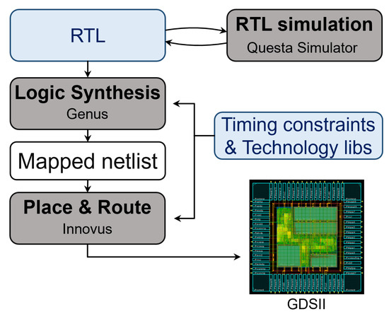
Figure 8.
The digital implementation flow from RTL to GDSII.
On the other hand, for completeness, we summarize in a common table at the end of the Evaluation section the characteristics of state-of-the-art fused architectures, with respect to the proposed designs, using as is the data presented in the corresponding papers.
It should be noted that FPGA-based experimental evaluation is deemed beyond the scope of this paper, since the proposed approach targets ASIC implementations exclusively. In order to yield meaningful insights, experiments on an FPGA would require our C++ code to target FPGA-specific optimizations amenable to the underlying FPGA fabric, i.e., DSP blocks. Such transformations are left as future work.
3.1. Identifying State-of-the-Art Non-Fused FP Vector Dot Product Configurations
FloPoCo does not support fused vector dot product units. So, our goal is to use FloPoCo and identify an optimal non-fused architecture by combining the available FP multipliers and adders and the many possible pipeline configurations that FloPoCo allows for each operator without support for de-normals. To better elucidate how we explored the available design space, we will use as an example the design of a 4-term dot product unit. This unit requires four multipliers to compute the four products in parallel, and three adders to construct the 4-to-1 reduction tree that will compute the final result of the dot product.
With the goal being to minimize the latency in cycles, the dot product unit can be designed using combinational multipliers and adders that are connected with intermediate pipeline stages. The performance of this approach, shown in Figure 9a, is bounded by the delay of the FP multipliers and adders. Alternatively, we could allow the multipliers and adders to be internally pipelined. Two alternatives emerge when using this approach. The one shown in Figure 9b pipelines the multiplier and the adders without using any extra pipeline registers between them. On the contrary, the second approach, shown in Figure 9c, allows for both internal and external pipelining, i.e., across the FP units. FloPoCo employs efficient architectures for the design of each FP multiplier [30] and FP adder [31]. The high-level organization of each unit is depicted at the bottom of Figure 9.
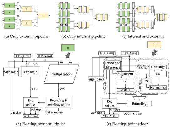
Figure 9.
Various pipelined organizations enabled by the FloPoco RTL generator for a 4-term dot product unit built from efficient FP multipliers and adders.
We examined 196 designs that cover 4 and 8-term dot products for the standard float and bloat16 formats targeting various clock frequencies. The results derived for the bloat16 format are summarized in Figure 10. The pareto curve inside each figure outlines the architectures with the least area at each delay target.
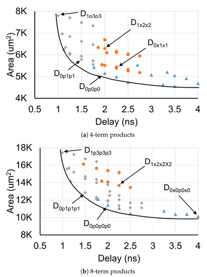
Figure 10.
The design-space exploration of 4- and 8-term dot products for the bfloat16 FP format generated with FloPoCo [22].
To uniquely identify each design choice in Figure 10, we follow a simple notation that describes the pipeline structure followed by each architecture. For instance, the design D0p0p0 that appears to be the best at 500 MHz in Figure 10a corresponds to the organization of Figure 9a for a 4-term product. The three zeros denote that each level of the dot product has zero inner pipeline stages and the letters ‘p’ between the zeros state that external pipelining is used across stages. On the other hand, D1p3p3 – the best choice when targeting a clock frequency of 1 GHz in Figure 10a—corresponds to a design of the category shown in Figure 9c. More specifically, it is 4-term design with multipliers having 1 inner pipeline stage, the adders of both levels have 3 inner pipeline stages, and extra pipeline registers are placed between the multipliers and adders. When an external pipeline stage is missing, letter ‘p’ is replaced with an ‘x’. The same structure is followed for the 8-term designs shown in Figure 10b, including more symbols per design due to the increased number of addition stages required.
3.2. Comparisons with the Proposed Fused Vector FP Dot Product Architecture
Having identified the best configurations of many design choices for 4- and 8-term dot products, we compare them with the equivalent proposed designs synthesized in RTL from Catapult HLS. The results obtained are summarized in Table 1. All designs are compared with respect to their area, power, and latency, under the same clock frequency constraint. The reported power was measured by running examples that cause, on average, a 25% toggle rate.

Table 1.
Comparison of the proposed 4- and 8-term fused FP dot product units relative to state-of-the-art non-fused designs.
For single-precision floats (FP32) and 4-term products, the proposed design achieves significantly lower latency and requires slightly less area than the corresponding state-of-the-art, at both clock frequency targets. For 8-term products, the proposed design achieves even higher reductions in latency. In general, the penalty for the comprehensive performance improvement achieved by the proposed design in FP32 is increased power consumption.
Instead, for bfloat16 (BF16), the proposed architecture excels in all three salient metrics. The improvement is greater at 1 GHz, where the latency is reduced by 40% and the area by around 14% for an 4-term unit, and by 57% and 18%, respectively, for an 8-term unit. Most importantly, these latency and area improvements at 1 GHz are achieved with similar power consumption. For instance, the layout of the two units under comparison for the case of a 4-term dot product of bfloats16 optimized for 1 GHz is shown in Figure 11.
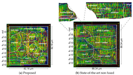
Figure 11.
The final layout for (a) the proposed and (b) the state-of-the-art non-fused 4-term dot product architectures, assuming a bfloat16 representation.
At 500 MHz, the power consumption of the proposed design is lower by 26% and 29% for 4-term and 8-term products, respectively, as compared to the state-of-the-art. This reduction in power consumption at 500 MHz is achieved with slightly less area and with similar (or slightly lower) latency.
Part of the efficiency of fused dot-product architectures stems from the fact that alignment, normalization, and rounding are performed only once and are not repeated in each individual multiply and add operation. This characteristic also favorably affects the numerical accuracy of the computation.
To evaluate the accuracy of the proposed fused vector dot-product unit, compared to a non-fused architecture, we computed 1 million dot products for different implementations and FP formats. For each test, the inputs were generated randomly, following a Gaussian distribution. In each case, the computation error is compared relative to the “golden values” computed using the double precision floating point datatype.
Figure 12 illustrates how the relative error scales with the increasing number of the dot product terms for (a) IEEE-754 single precision data in, and (b) for bfloat16 data. When looking at the error of the non-fused architecture, we can see that it scales with the number of terms in the dot product calculation. This is due to the increasing amount of intermediate rounding that is performed at the end of each individual adder or multiplier that comprise the design. On the other hand, the relative error of the proposed units remains constant and close to the minimum step between two consecutive floating point numbers. This behavior is due to the increased internal data width datapath used in all cases. which increases linearly with the number of terms of the dot product. A similar technique was used in Intel’s Nervana NPP-T [14] fused architecture, where the width of the final accumulator was selected so that it could compute every dot product in its supported applications, without a loss in accuracy.
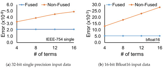
Figure 12.
The error introduced by the fused and non-fused architectures for two different FP formats when computing dot products with increasing number of terms, relative to the same computation implemented with double-precision (64-bit) FP arithmetic.
3.3. Performance Summary of Fused Dot Product Architectures
Even though fused vector dot product designs are not available as open-source, we summarize—for completeness—in Table 2 the characteristics of efficient fused vector dot product architectures and of the proposed design. The data for the competing approaches is taken verbatim from the corresponding papers. Obviously, one of the key strengths of the proposed approach is its templatized nature (unique in Table 2) that provides designers with unprecedented flexibility. This flexibility, in conjunction with HLS, fine-tune the resulting implementation for the specified design constraints and FP format. Consequently, as evidenced in Table 2, the proposed approach leads to balanced design configurations where the pipeline latency, clock frequency, and area are cohesively optimized.

Table 2.
Comparison between the different fused floating-point vector dot product architectures.
4. Conclusions
Implementing the many-term FP dot product units required in the majority of deep learning applications with a fused architecture leads to highly efficient solutions, in terms of latency, area, and power. To enhance the scope of fused architectures on high-level synthesis design flows that support custom-precision FP arithmetic, we designed them as templatized soft FP cores that allow the designers to use them with arbitrary FP types in their C++ HLS models. The design is available under a permissive open-source license as part of the header-only FastFloat4HLS library [21]. The experimental results that compare the proposed approach to state-of-the-art non-fused many-term dot product architectures show that it can achieve lower latency and area at the same clock frequency, while its power consumption depends on the chosen FP format.
Author Contributions
All authors have contributed equally and substantially to all parts of this manuscript. D.F., C.N. and G.D.; methodology, D.F., C.N. and G.D.; writing, D.F., C.N. and G.D. All authors have read and agreed to the published version of the manuscript.
Funding
This work was supported by a research grant from Siemens EDA to Democritus University of Thrace for “High Level Synthesis Research for Systems-on-Chip”.
Institutional Review Board Statement
Not applicable.
Informed Consent Statement
Not applicable.
Data Availability Statement
Not applicable.
Conflicts of Interest
The authors declare no conflict of interest.
References
- Liu, Z.; Mao, H.; Wu, C.Y.; Feichtenhofer, C.; Darrell, T.; Xie, S. A convnet for the 2020s. In Proceedings of the IEEE/CVF Conference on Computer Vision and Pattern Recognition, New Orleans, LA, USA, 18–24 June 2022; pp. 11966–11976. [Google Scholar]
- Jouppi, N.P.; Hyun Yoon, D.; Ashcraft, M.; Gottscho, M.; Jablin, T.B.; Kurian, G.; Laudon, J.; Li, S.; Ma, P.; Ma, X.; et al. Ten lessons from three generations shaped Google’s TPUv4i: Industrial product. In Proceedings of the ACM/IEEE International Symposium on Computer Architecture (ISCA), Valencia, Spain, 14–18 June 2021; pp. 1–14. [Google Scholar]
- Sze, V.; Chen, Y.H.; Yang, T.J.; Emer, J.S. Efficient processing of deep neural networks: A tutorial and survey. Proc. IEEE 2017, 105, 2295–2329. [Google Scholar] [CrossRef]
- Gholami, A.; Kim, S.; Dong, Z.; Yao, Z.; Mahoney, M.W.; Keutzer, K. A survey of quantization methods for efficient neural network inference. arXiv 2021, arXiv:2103.13630. [Google Scholar]
- Wang, S.; Kanwar, P. BFloat16: The secret to high performance on Cloud TPUs. Google Cloud Blog 2019. Available online: https://cloud.google.com/blog/products/ai-machine-learning/bfloat16-the-secret-to-high-performance-on-cloud-tpus (accessed on 10 September 2022).
- Andersch, M.; Palmer, G.; Krashinsky, R.; Stam, N.; Mehta, V.; Brito, G.; Ramaswamy, S. NVIDIA Hopper Architecture. Available online: https://developer.nvidia.com/blog/nvidia-hopper-architecture-in-depth (accessed on 11 September 2022).
- Agrawal, A.; Mueller, S.M.; Fleischer, B.M.; Sun, X.; Wang, N.; Choi, J.; Gopalakrishnan, K. DLFloat: A 16-b Floating Point format designed for Deep Learning Training and Inference. In Proceedings of the International Symposium on Computer Arithmetic (ARITH), Kyoto, Japan, 10–12 June 2019. [Google Scholar]
- Micikevicius, P.; Stosic, D.; Burgess, N.; Cornea, M.; Dubey, P.; Grisenthwaite, R.; Ha, S.; Heinecke, A.; Judd, P.; Kamalu, J.; et al. FP8 Formats for Deep Learning. arXiv 2022, arXiv:2209.05433. [Google Scholar]
- Tambe, T.; Yang, E.Y.; Wan, Z.; Deng, Y.; Janapa Reddi, V.; Rush, A.; Brooks, D.; Wei, G.Y. Algorithm-Hardware Co-Design of Adaptive Floating-Point Encodings for Resilient Deep Learning Inference. In Proceedings of the Design Automation Conference (DAC), San Francisco, CA, USA, 20–24 July 2020; pp. 1–6. [Google Scholar]
- Kim, D.; Kim, L.S. A floating-point unit for 4D vector inner product with reduced latency. IEEE Trans. Comp. 2008, 58, 890–901. [Google Scholar] [CrossRef]
- Saleh, H.H.; Swartzlander, E.E. A floating-point fused dot-product unit. In Proceedings of the 2008 IEEE International Conference on Computer Design, Lake Tahoe, CA, USA, 12–15 October 2008; pp. 427–431. [Google Scholar]
- Sohn, J.; Swartzlander, E.E. Improved architectures for a floating-point fused dot product unit. In Proceedings of the IEEE Symposium on Computer Arithmetic (ARITH), Austin, TX, USA, 7–10 April 2013; pp. 41–48. [Google Scholar]
- Kaul, H.; Anders, M.; Mathew, S.; Kim, S.; Krishnamurthy, R. Optimized fused floating-point many-term dot-product hardware for machine learning accelerators. In Proceedings of the IEEE Symposium on Computer Arithmetic (ARITH), Kyoto, Japan, 10–12 June 2019; pp. 84–87. [Google Scholar]
- Hickmann, B.; Chen, J.; Rotzin, M.; Yang, A.; Urbanski, M.; Avancha, S. Intel Nervana Neural Network Processor-T (NPP-T) Fused Floating Point Many-Term Dot Product. In Proceedings of the IEEE Symposium on Computer Arithmetic (ARITH), Portland, OR, USA, 7–10 June 2020; pp. 133–136. [Google Scholar]
- Micikevicius, P.; Narang, S.; Alben, J.; Diamos, G.; Elsen, E.; Garcia, D.; Ginsburg, B.; Houston, M.; Kuchaiev, O.; Venkatesh, G.; et al. Mixed precision training. arXiv 2017, arXiv:1710.03740. [Google Scholar]
- Burgess, N.; Milanovic, J.; Stephens, N.; Monachopoulos, K.; Mansell, D. Bfloat16 processing for neural networks. In Proceedings of the 2019 IEEE 26th Symposium on Computer Arithmetic (ARITH), Kyoto, Japan, 10–12 June 2019; pp. 88–91. [Google Scholar]
- Siemens EDA. Algorithmic C (AC) Datatypes Reference Manual. Available online: https://github.com/hlslibs/ac_types (accessed on 11 September 2022).
- Thomas, D.B. Templatised soft floating-point for high-level synthesis. In Proceedings of the IEEE International Symposium on Field-Programmable Custom Computing Machines (FCCM), San Diego, CA, USA, 28 April–1 May 2019; pp. 227–235. [Google Scholar]
- Xilinx. Vitis HLS Hardware Design Methodology—Arbitrary Precision Datatypes—Floats and Doubles. Available online: https://docs.xilinx.com/r/en-US/ug1399-vitis-hls/Floats-and-Doubles (accessed on 11 September 2022).
- Uguen, Y.; Dinechin, F.D.; Lezaud, V.; Derrien, S. Application-specific arithmetic in high-level synthesis tools. ACM Trans. Archit. Code Optim. (TACO) 2020, 17, 1–23. [Google Scholar] [CrossRef]
- IC-Lab-DUTH Repository. FastFloat4HLS C++ Library. Available online: https://github.com/ic-lab-duth/Fast-Float4HLS (accessed on 11 September 2022).
- De Dinechin, F.; Pasca, B.; Normale, E. Custom arithmetic datapath design for FPGAs using the FloPoCo core generator. IEEE Design Test Comp. 2011, 28, 18–27. [Google Scholar] [CrossRef]
- Hickmann, B.; Bradford, D. Experimental Analysis of Matrix Multiplication Functional Units. In Proceedings of the IEEE Symposium on Computer Arithmetic (ARITH), Kyoto, Japan, 10–12 June 2019; pp. 116–119. [Google Scholar]
- Käsgen, P.; Weinhardt, M. Using Template Metaprogramming for Hardware Description; Universität Tübingen: Tübingen, Germany, 2018. [Google Scholar]
- Fingeroff, M. High-Level Synthesis: Blue Book; Xlibris Corporation: Bloomington, IN, USA, 2010. [Google Scholar]
- Dimitrakopoulos, G.; Galanopoulos, K.; Mavrokefalidis, C.; Nikolos, D. Low-Power Leading-Zero Counting and Anticipation Logic for High-Speed Floating Point Units. IEEE Trans. Very Large Scale Integr. (VLSI) 2008, 16, 837–850. [Google Scholar] [CrossRef]
- Siemens EDA. Questa Advanced Simulator. Available online: https://eda.sw.siemens.com/en-US/ic/questa/simulation/advanced-simulator/ (accessed on 11 September 2022).
- Cadence. Genus Synthesis Solution. Available online: https://www.cadence.com/en_US/home/tools/digital-design-and-signoff/synthesis/genus-synthesis-solution.html (accessed on 11 September 2022).
- Cadence. Innovus Implementation System. Available online: https://www.cadence.com/en_US/home/tools/digital-design-and-signoff/soc-implementation-and-floorplanning/innovus-implementation-system.html (accessed on 11 September 2022).
- Galal, S.; Horowitz, M. Latency Sensitive FMA Design. In Proceedings of the IEEE Symposium on Computer Arithmetic (ARITH), Tübingen, Germany, 25–27 July 2011; pp. 129–138. [Google Scholar]
- Seidel, P.M.; Even, G. On the design of fast IEEE floating-point adders. In Proceedings of the IEEE Symposium on Computer Arithmetic (ARITH), Vail, CO, USA, 11–13 June 2001; pp. 184–194. [Google Scholar]
Publisher’s Note: MDPI stays neutral with regard to jurisdictional claims in published maps and institutional affiliations. |
© 2022 by the authors. Licensee MDPI, Basel, Switzerland. This article is an open access article distributed under the terms and conditions of the Creative Commons Attribution (CC BY) license (https://creativecommons.org/licenses/by/4.0/).