Abstract
The fractional-order lung impedance model of the human respiratory tree is implemented in this paper, using Operational Transconductance Amplifiers. The employment of such active element offers electronic adjustment of the impedance characteristics in terms of both elements values and orders. As the MOS transistors in OTAs are biased in the weak inversion region, the power dissipation and the dc bias voltage of operation are also minimized. In addition, the partial fraction expansion tool has been utilized, in order to achieve reduction of the spread of the required time-constants and scaling factors. The performance of the proposed scheme has been evaluated, at post-layout level, using MOS transistors models provided by the 0.35 m Austria Mikro Systeme technology CMOS process, and the Cadence IC design suite.
1. Introduction
Fractional calculus is a branch of mathematical analysis which forms a more general description of the conventional integer-order calculus. As it is well known, integer-order calculus deals with differentiation that, given a function , is described by the expression , where is an integer number . In fractional calculus, the same expression describes the differentiation, yet the order is now a real number, leading to a wider range of values. The idea of fractional derivative dates back to the end of the 17-th century; it is not until the past few decades, however, when fractional calculus started being used for a variety of scientific problems and applications. The cause of its increasing application is that, as mentioned above, it forms a generalization of the traditional calculus, and thus describes more real problems with higher accuracy [1,2,3,4]. One of the most popular methods, that makes the analysis of a real system easier, is the Laplace transform. This is an efficient way to describe and solve equations in frequency domain with simple calculations and without transformations to time domain during the process. The Laplace transform of the derivative of a function, , in the fractional domain is: for zero initial conditions [1]. Employing this definition, the impedance in the fractional-domain has the general form:
where the variable a represents the order of the element. For the element is called fractional-order capacitor, or sometimes Constant Phase Element (CPE), with being the pseudo-capacitance in Farad/sec
1−. In the case that the expression in (1) represents a fractional-order inductor with being the pseudo-inductance in Henry/sec
1−. When , the element is a resistor, capacitor, and inductor, respectively.
Fractional-order modeling considers the effects of the long-term memory, and due to the offered extra degrees of freedom, it is suitable for modeling, analyzing, and synthesizing electrical, chemical, and biological systems [5,6,7,8,9,10,11,12]. In particular, circuit emulators of individual parts of the human body and even the complete human body play an important role for fast and accurate diagnosis of different diseases and morphological changes arising from environmental impacts such as long time exposure to pollution and contamination. For example, the complete human body impedance model studied in [13,14] offers circuits more accurate than the international IEC 60990 safety standard. It is impossible to test the safety of any designed instrument on real humans and therefore, tests are conducted on circuit models. In a similar manner, circuit models for specific human organs have been widely proposed and used to characterize changes that occur in these organs as a result of diseases, pollution or other types of damages. In this regards, the clear relationship between fractional-order models and fractal geometry has already been highlighted in different articles (see for example [15]). Fractal geometry is especially visible in the tissue structure of the lungs [16]. However, the large variations in the circuit model parameters from one human to the other require developing electronically-adjustable circuits that can be re-configured easily to reflect these changes and allow future integration in smart point of care bio-medical devices (see [17]).
Lungs are located in the chest on either side of the heart in the rib cage. Their purpose is to provide oxygen to the blood [18]. Their shape is conical with a narrow rounded apex at the top, and a broad concave base that rests on the convex surface of the diaphragm. Due to the presence of the heart, the left lung is slightly smaller than the right. Lungs are part of the lower respiratory track beginning from trachea and followed by bronchi and bronchioles. The bronchial tree is a series of passages that supplies air to the alveoli of the lungs. It begins with the trachea, which divides into a left and right bronchus. Broncholies are divided into alveolar ducts that create the alveolar sacs, which contains the alveoli, where gas exchanging happens [19]. Oxygen breathed in and carbon dioxide breathed out. Due to its airway’s branches self similarities (fractal geometry), lungs are a great candidate for the application of fractional-order calculus theory [20,21,22,23,24,25,26]. At a low frequency range inheritance is insignificant, so each airway can be modeled by a gamma cell resistance and capacitance. In biology, when a circuit shares the same impedance with a tissue in a specific frequency range, then it is called equivalent circuit. Although the model that is used to characterize viscoelastic behavior is composed of two resistors and one capacitor, in the case of lungs the electrical equivalent impedance of each airway is considered to be consisted of one resistor and one capacitor [27]. Theoretically, the air flow will be the electric current and the air pressure will be the voltage, respectively.
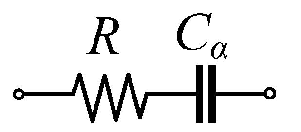
Regarding to the above description the electrical equivalent, shown in Figure 1, consists of a series connection of a passive resistor and a fractional-order capacitor. The equivalent impedance is given by (2)
with R being an ohmic resistance, being the pseudo-capacitance and being the order of the element [16].
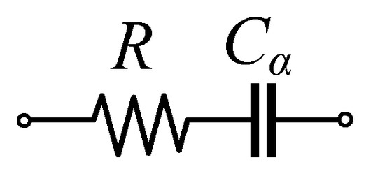
Figure 1.
Fractional-order electrical equivalent of the impedance of the lung in the human respiratory tree [16].
The (scaled) values of the resistances and pseudo-capacitances, as well as of the order of the fractional-order capacitors, taken from seven subjects in the range [0.9 Hz, 6 Hz] are summarized in Table 1.

Table 1.
Values of the elements of the fractional-order electrical equivalent of the impedance of the lung in the human respiratory tree [16].
Table 1 of the manuscript shows that the measured circuit parameters for 7 individuals have a variation in pseudo-capacitance of more than 14 times (from 17.5 nFarad/s0.05 to 238 nFarad/s0.42). Also, the variation in the dispersion coefficient from 0.6 to nearly double the value at 1.1 indicates the importance of re-configurability of any proposed circuit model in order to reflect the measured values of any particular individual, which is the focus of this work.
Owing to the fact that fractional-order capacitors are not available in the market [28], their behavior is approximated through the employment of RC networks [29], or the employment of the gyration techniques implemented using active elements [10]. The first solution is easily realizable, but it does not offer the capability of programming because the values of all passive elements must be changed, in order to change the characteristics of the element. On the other hand, the second method offers electronic adjustment of the characteristics of the element, but this is achieved at the expense of circuit complexity and active component count. The contribution, made in this work, is that a novel solution for implementing emulators of fractional-order capacitors with order in the range (0, 2), which offers significant reduction of the spread of time-constants and scaling factors with regards to the straightforward implementation [30], is presented. This also leads to a significant reduction of the total capacitance area and the total power dissipation. All the above have been achieved keeping: (a) the fully electronic adjustment of the characteristics of the capacitor, including its value as well as its order, and (b) the capability of emulating fractional-order capacitors with order greater than one by the same core.
The paper is organized as follows: the procedure for emulating the behavior of the fractional-order capacitors is presented in Section 2, while the circuit implementation of the proposed scheme is given in Section 3. The performance of the intermediate stages and of the whole system are evaluated at post-layout level in Section 4, using the Cadence IC design suite and MOS transistor models provided by the Austria Mikro Systeme (AMS) 0.35 m CMOS process.
2. Emulation of Fractional-Order Capacitors
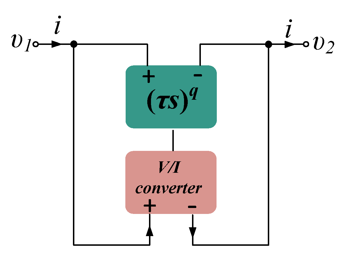
According to [30], the emulation of a fractional-order capacitor is preformed through the utilization of the Functional Block Diagram (FBD) depicted in Figure 2. The equivalent impedance is given by the expression in (3)
with being the transconductance parameter of the voltage-to-current () converter, being a time-constant associated to the unity-gain frequency () of the differentiator according to the formula: , and being the order of the differentiator. The value of the emulated pseudo-capacitance has the form of (4)
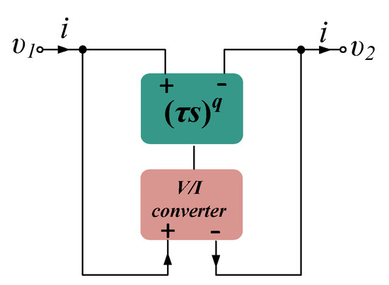
Figure 2.
Functional block diagram for emulating a fractional-order capacitor of order [30].
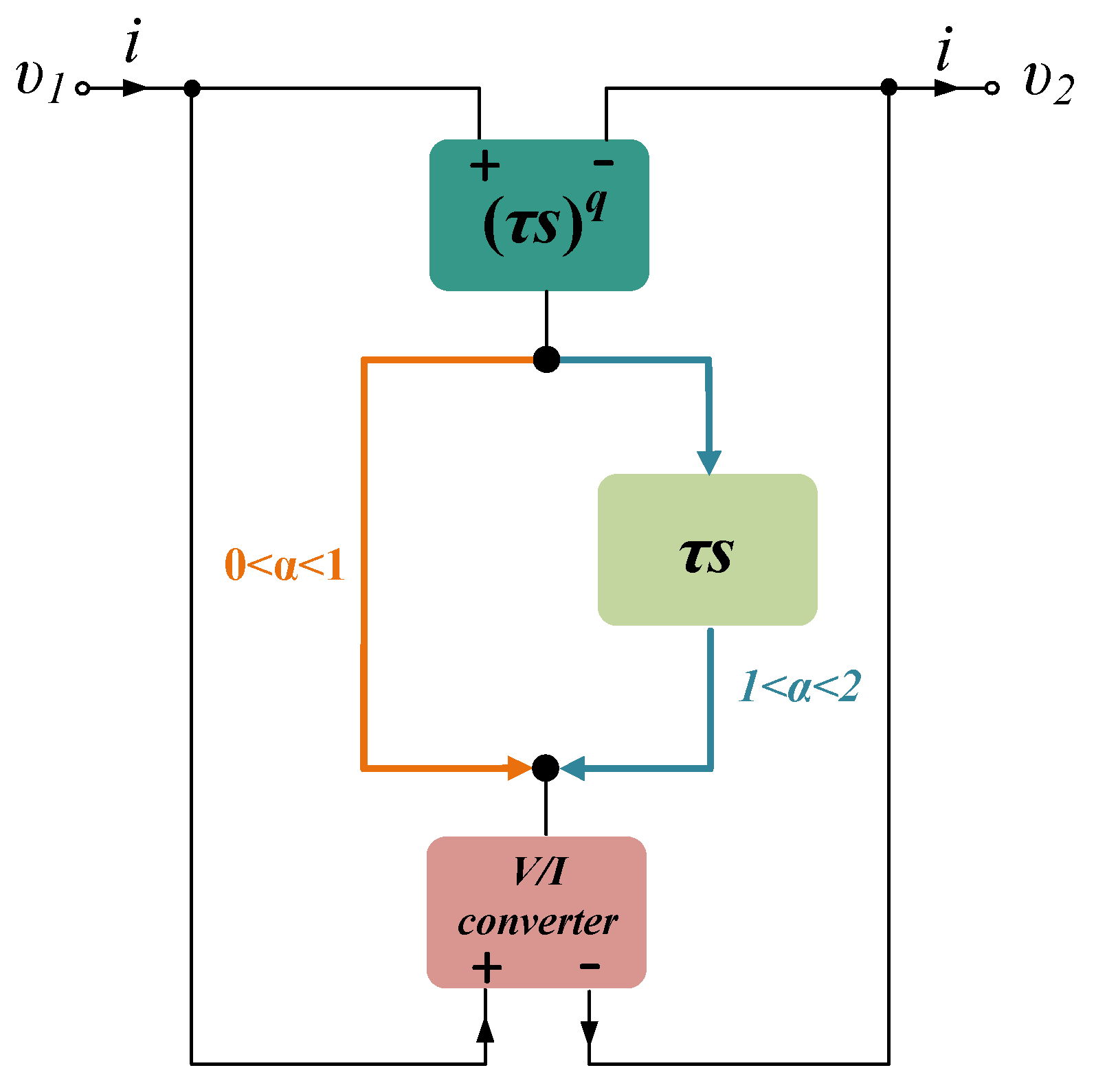
Due to the restriction on the values range of the variable q, only the cases #1 to #6 (i.e., ) are implementable. The last case in Table 1, where the order of the fractional-order capacitor is greater than one (i.e., ), cannot be emulated by the present form of the FBD in Figure 2. In order to overcome this obstacle, the modified FBD in Figure 3 will be utilized, using an extra integer-order differentiator stage between the fractional-order differentiator and the converter and, thus, [31].
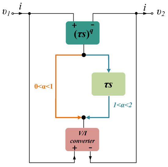
Figure 3.
Functional block diagram for emulating a fractional-order capacitor of order [31].
As the equivalent in Figure 1 is valid over the frequency range f = [0.9 Hz, 6 Hz], an appropriate selection of unity-gain frequency of the differentiator () could be 2.5 Hz. The values of the pseudo-capacitance and the order of the fractional-order elements, along with the values of the order q of the fractional-order differentiator and the transconductance of the FBD in Figure 3, for the seven cases of emulation are summarized in Table 2.

Table 2.
Values of the elements of the fractional-order emulator in Figure 3.
Taking also into account the results provided in [32], the 2nd-order Continued Fraction Expansion (CFE) approximation will be utilized for approximating the behavior of the fractional-order differentiator with an error less than 5% in the frequency range of interest. The resulted rational transfer function has the form
where in (5) the coefficients and are positive real numbers provided in [33].
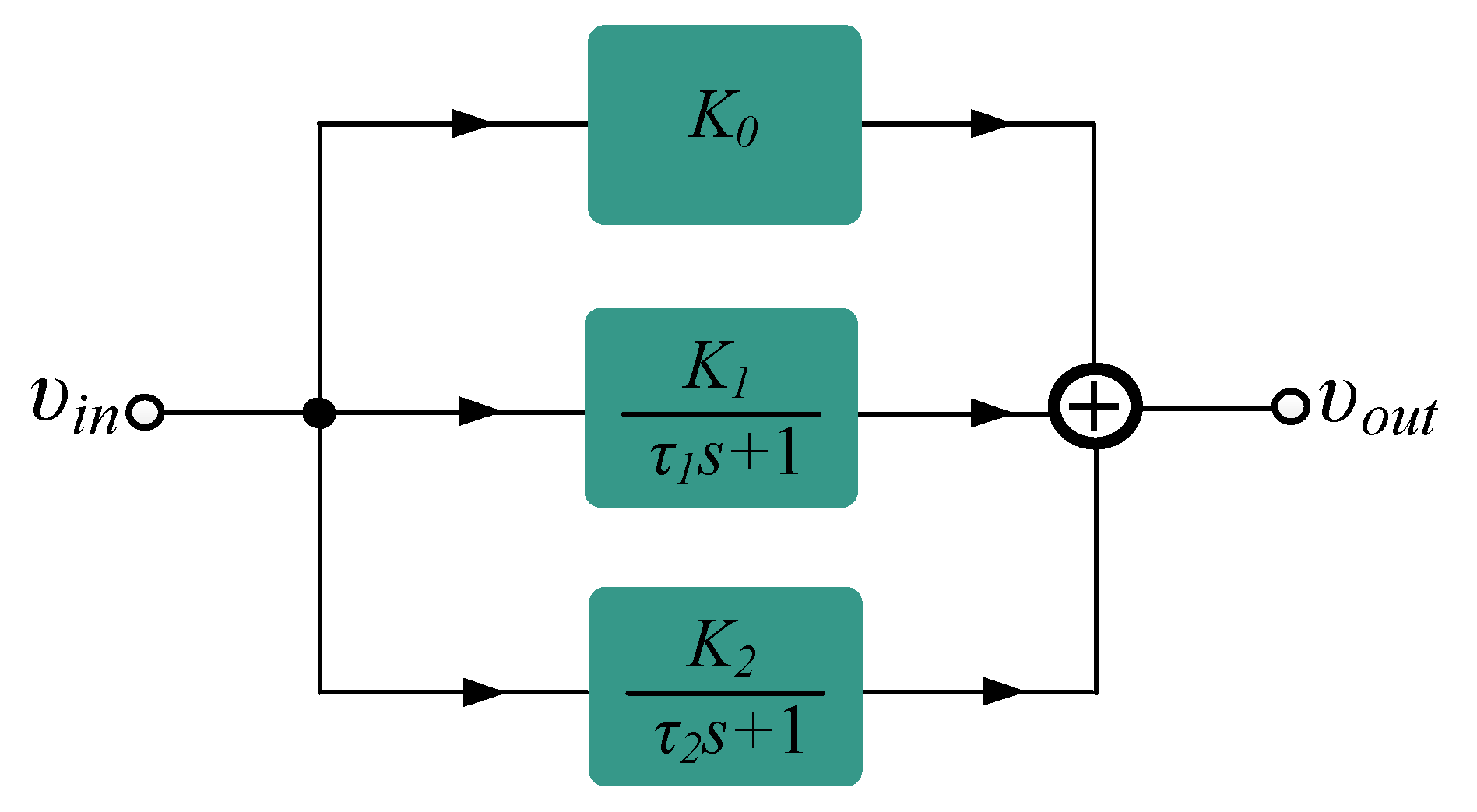
The implementation of (5) can be performed using the multi-feedback Inverse-Follow-the-Leader- Feedback (IFLF) structure demonstrated in Figure 4, where the realized transfer function is

Figure 4.
FBD of an Inverse-Follow-the-Leader-Feedback topology for approximating a fractional-order differentiator using the Continued Fraction Expansion tool [30].
The values of scaling factors and time-constants are calculated by equating the coefficients of the numerator and denominator of (5) and (6) [10]. The resulted values are summarized in Table 3. Considering the spread (i.e., the ratio of the maximum and minimum value) of both scaling factors and time-constants, it is derived that the spread of scaling factors for all possible cases is equal to 12, 174, while for the time-constants the corresponding value is 388. Taking into account that in the case of employing OTAs these scaling factors will be controlled by dc currents, it is readily obtained that an extremely wide range of bias currents is required towards this goal.

Another possible solution for overcoming this practical problem is the utilization of the Partial Fraction Expansion (PFE) method introduced in [34]. According to this, the transfer function in (5) can be decomposed in the form of (7)
where are the residues of (5), are the poles of (5) and .
The expression in (7) can be alternatively written as
where and . The implementation of (8) can be performed by the functional block diagram given in Figure 5. Using (5), (7) and (8), the resulted values of times constants are summarized in Table 4. The spread of scaling factors is now significantly reduced into the value 884 and the spread of time-constants is now equal to 362, more or less the same as in the previous case. Therefore, the PFE approximation tool is preferable than the CFE tool with regards to reduction of the spread of scaling factors.
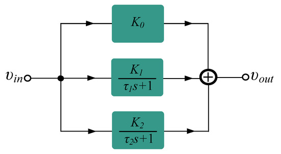
Figure 5.
FBD for approximating a fractional-order differentiator using the Partial Fraction Expansion tool [34].
3. Circuit Implementation
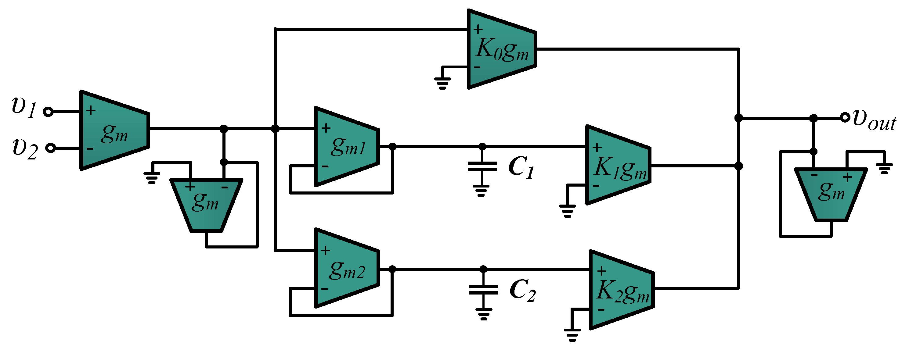
In order to approximate the fractional-order differentiator stage, which is required in the functional block diagram in Figure 3, the OTA-C topology depicted in Figure 6 will be utilized. This topology implements the transfer function in (8); the values of scaling factors, provided in Table 4, are performed through an appropriate scaling of the corresponding transconductances and, also, their signs are implemented through an appropriate configuration of the input terminals of the corresponding OTAs. The realized time-constants are given by the general expression in (9)
with and being the transconductance of the OTAs and the capacitance associated to the jth- integration stage.
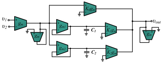
Figure 6.
Implementation of the fractional-order differentiation stage, required for the implementation of the functional block diagram in Figure 3.
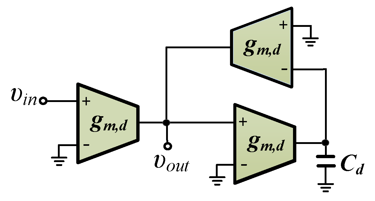
The integer-order differentiator is implemented by the topology demonstrated in Figure 7 [35], and the realized transfer function is given by (10)
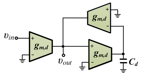
Figure 7.
Implementation of the integer-order differentiation stage, required for the implementation of the functional block diagram in Figure 3 [35].
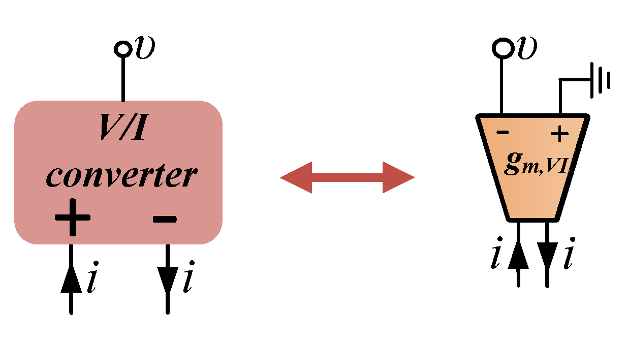
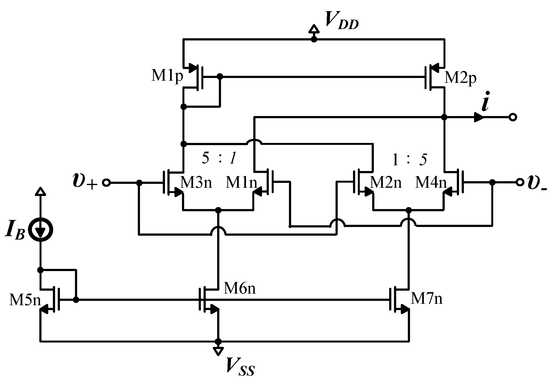
The conversion stage is implemented by the multiple-output OTA configuration depicted in Figure 8, with the conversion gain being equal to .
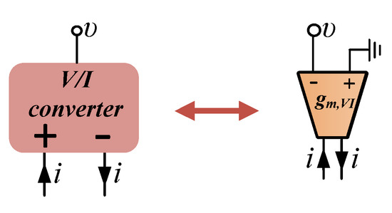
Figure 8.
Implementation of the converter stage using an appropriately configured multiple- output OTA.
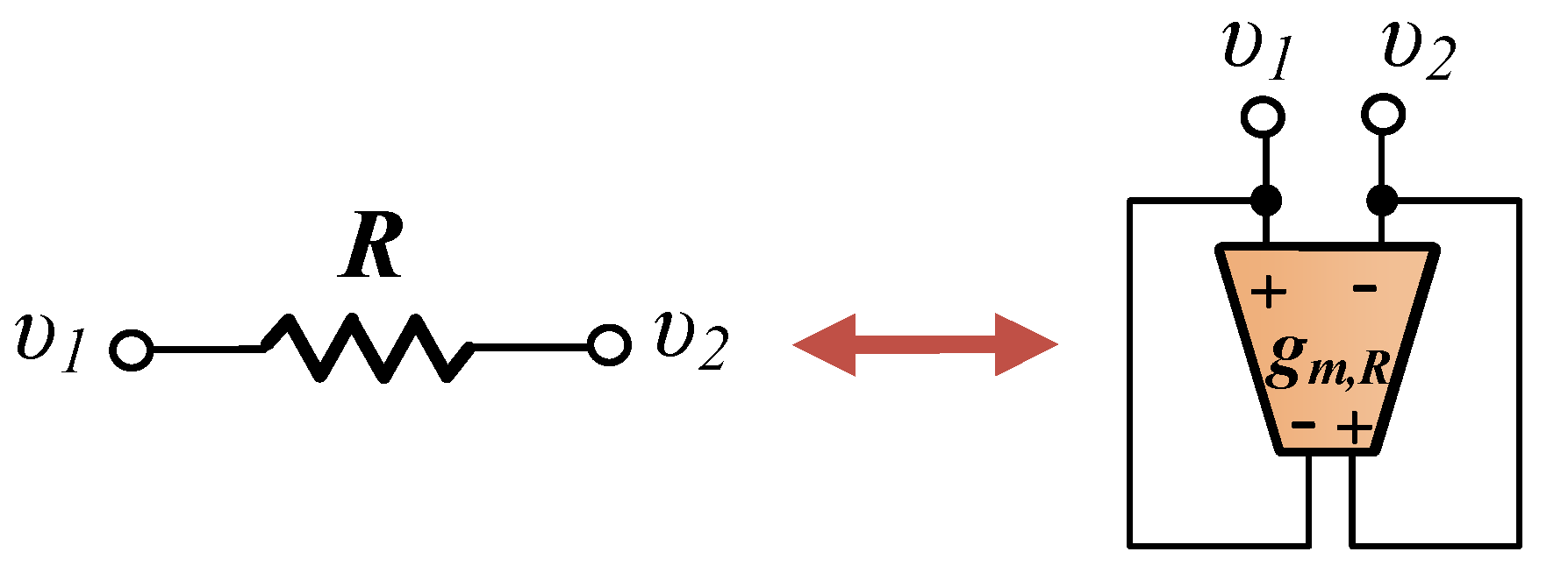
In order to implement the whole model, which is provided in Figure 1, a floating resistor emulator is also required. This is realized by the topology, given in Figure 9, where the realized resistance is .
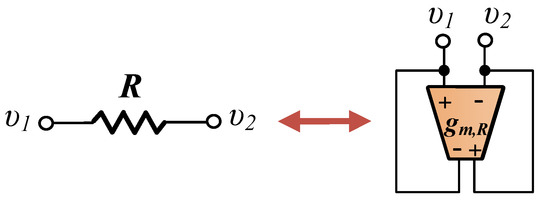
Figure 9.
Implementation of a floating resistor using an appropriately configured multiple-output OTA.
A possible OTA topology, in order to implement the topologies in Figure 6, Figure 7, Figure 8 and Figure 9, is that presented in Figure 10, which is capable of handling input voltages with maximum amplitude 50 mV, with a total harmonic distortion less than 1% [36]. Considering MOS transistors biased in the sub-threshold region, the realized transconductance is
with being the bias current, being the sub-threshold slope factor, and (≃26 mV at 27 C) being the thermal voltage. Using (9) and (11), the resulted expression of the realized time-constants is that given by (12)
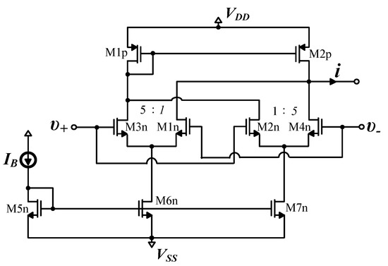
According to (11) and (12), the temperature variations affect both the implemented values of transconductance and time-constant due to the dependence of thermal voltage from the temperature. This can be compensated by employing proportional to the absolute temperature (PTAT) dc current sources [37].
4. Simulation Results
Using the expression in (12) and considering that = 5 pF, = 70 pF, then the calculated values of the dc bias currents, required for realizing the time-constants in Table 4, are provided in Table 5. The scaling factors {} were implemented by multiplying the dc bias current by these factors, as it is derived from (11). Using (10) and (12), and considering that = 25 pF, the dc bias current of the OTAs employed for implementing an integer-order differentiator with time-constant 63.69 ms (i.e., = 2.5 Hz) was equal to 22.1 pA. In addition, the values of the dc bias currents for implementing the converter stage and the floating resistors, calculated using (4), (11) and Table 1, are given in Table 5. The evaluation of the behavior of the proposed lung impedance model will be performed using the Cadence IC design suite and MOS transistor models provided by the Austria Mikro Systeme (AMS) 0.35 m CMOS process. Considering that = 0.75 V, the MOS transistors aspect ratios of the OTAs used in Figure 6, Figure 7 and Figure 8, selected in such way that all transistors will operate in the sub-threshold region, are provided in Table 6.


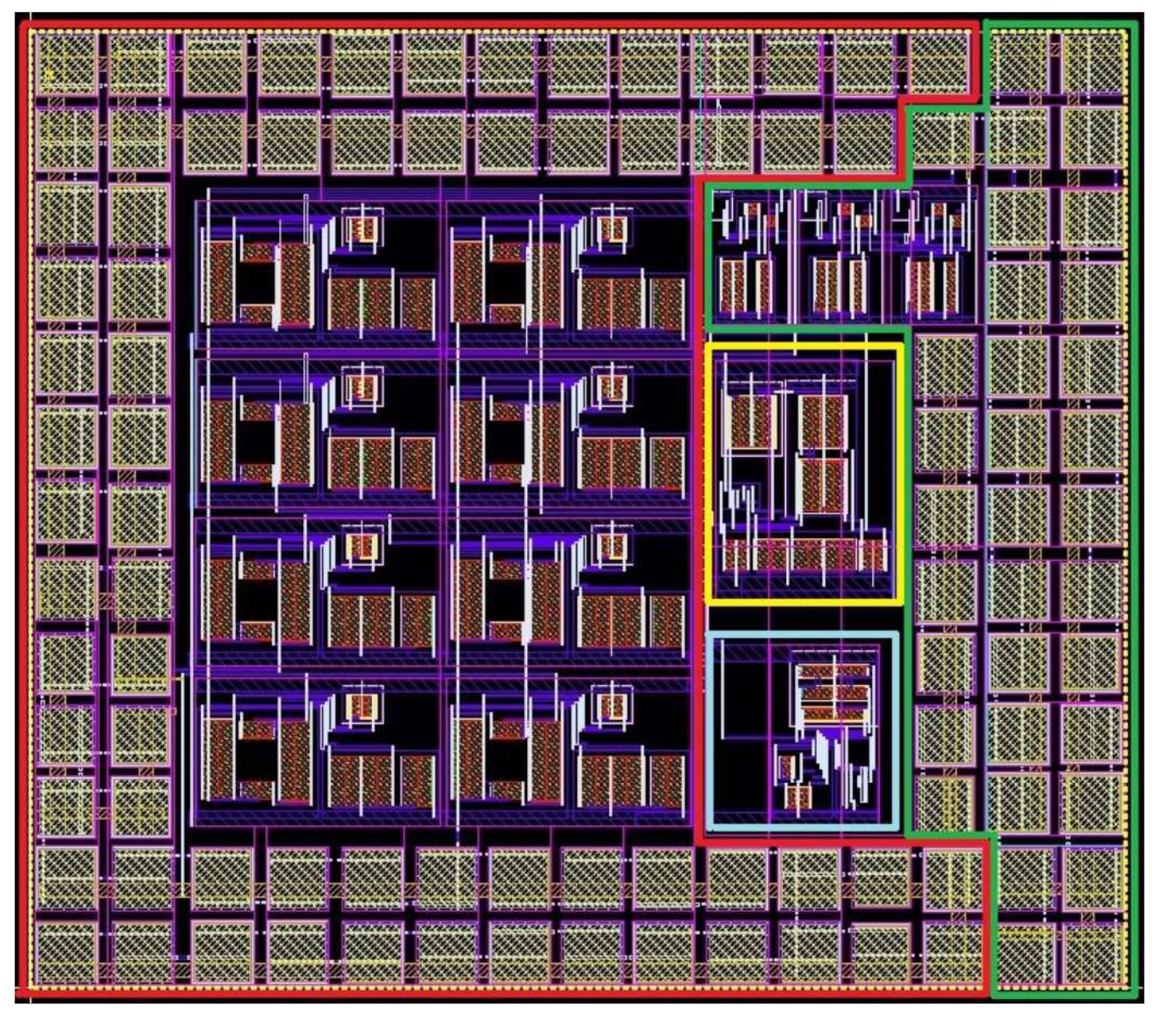
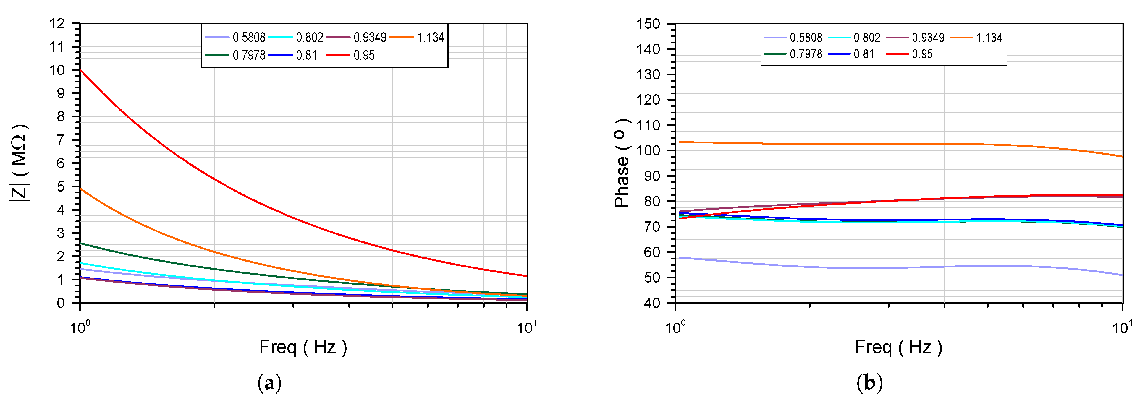
The layout design of the proposed lung impedance emulator is demonstrated in Figure 11, where the silicon area is 555.35 m × 485.75 m. As a first-step the correct operation of the building blocks of the model in Figure 1 was verified. The obtained impedance magnitude and phase responses of the CPE emulator are given in Figure 12. The characteristic values of the gain and phase of the fractional-order differentiator at the center frequency of the approximation (i.e., = 2.5 Hz) as well as the values of the implemented resistances of the employed converter stage in Figure 8 and resistor emulator in Figure 9 are summarized in Table 7, with the corresponding theoretically predicted values (i.e., derived using ideal circuit elements) given in parentheses. The gain and phase of the integer-order differentiator in Figure 7 at frequency = 2.5 Hz, which is used in the case #7 for implementing the order , were 1 and +88.3° with the theoretical values being 1 and +90°, respectively.
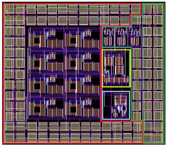
Figure 11.
Layout design of the proposed emulator of the lung impedance model of the human respiratory tree in Figure 1 (fractional-order differentiator in red polygon, integer-order differentiator in green polygon, converter in yellow polygon, and active resistor in blue polygon).
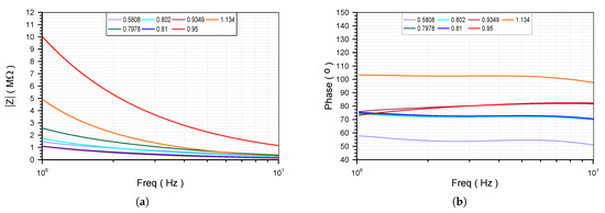

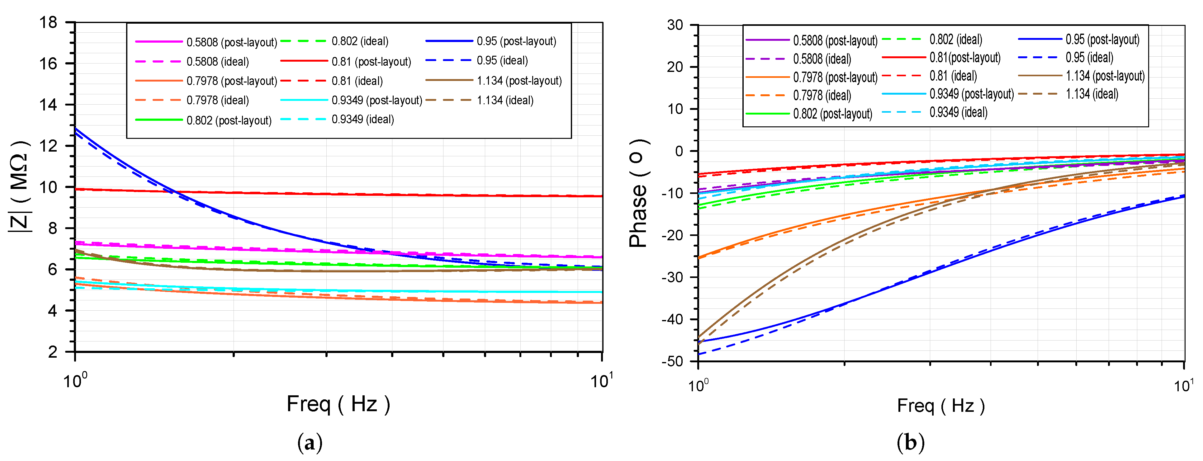
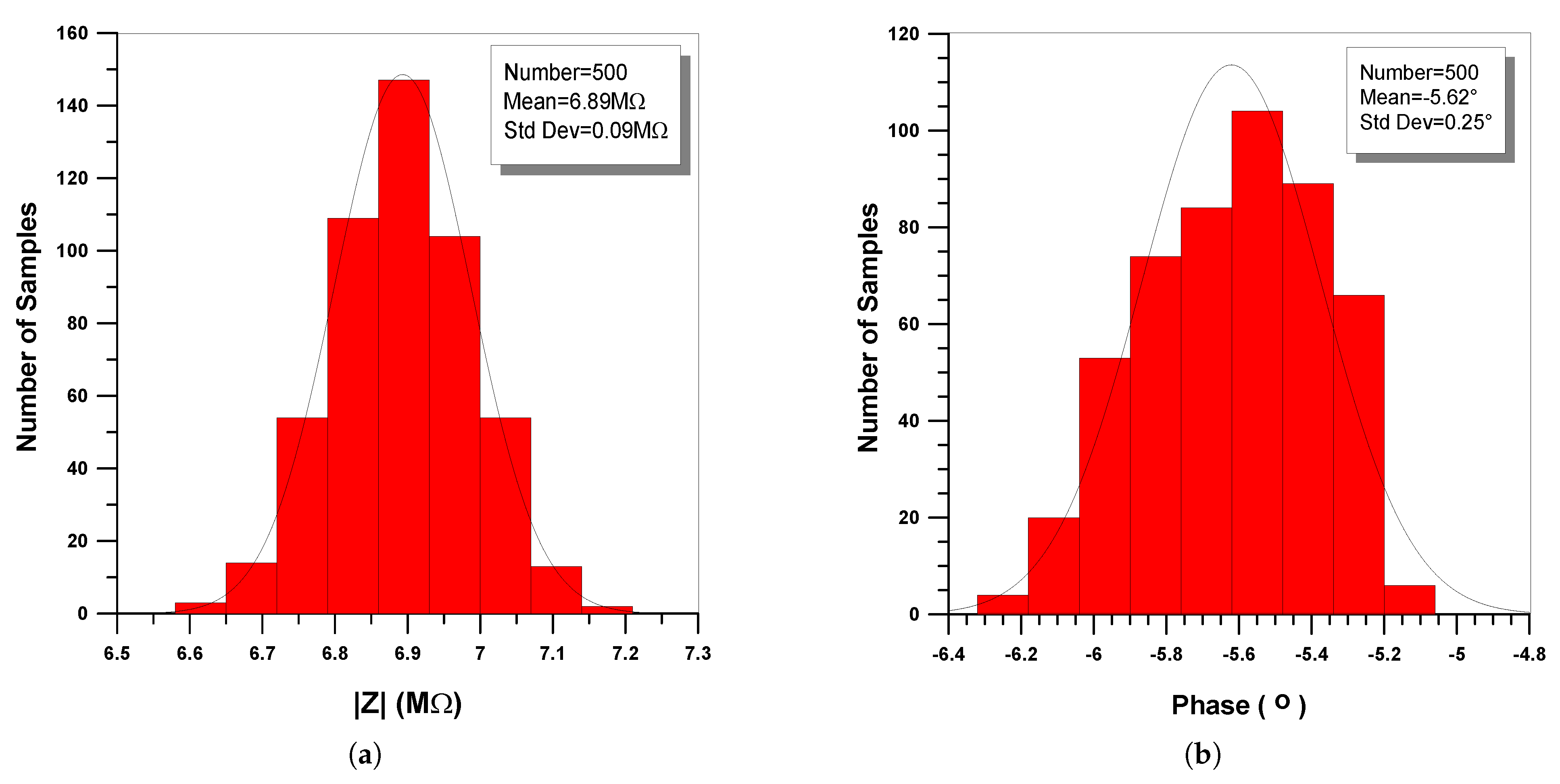
The second step is the consideration of the total circuit of the lung impedance emulator in Figure 11. The obtained impedance magnitude and phase responses are provided in Figure 13, where the corresponding theoretically predicted plots are given by dashes. The most important performance characteristics are given in Table 8, along with the theoretical values given between parentheses. Considering the case R = 6.44 M, = 238 nF/s and = 0.5808, the derived statistical plots about the magnitude and phase of the impedance at the center frequency of the approximation (i.e., = 2.5 Hz) are provided in Figure 14.
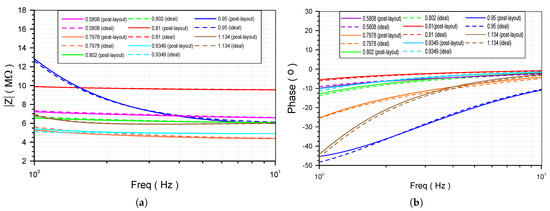
Figure 13.
Post-layout frequency responses of the lung impedance (a) magnitude, and (b) phase.

Table 8.
Simulated and theoretical (in parentheses) values of impedance magnitude and phase of the model in Figure 1, at the center frequency of the approximation ( = 2.5 Hz).
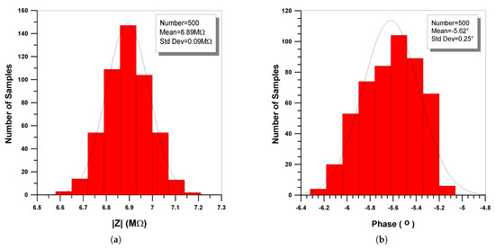
Figure 14.
Statistical histograms about the sensitivity of the (a) magnitude, and (b) phase of the lung impedance, at the center frequency of the approximation ( = 2.5 Hz).
These results are derived, by employing the Monte-Carlo analysis offered by the Analog Design Environment of the Cadence IC design suite, for a number of runs and considering variations of the channel width and length, gate oxide thickness, threshold voltage, carrier mobility, and substrate and channel doping concentration. The values of standard deviation were 0.09 M and , with the nominal values being 6.89 M and , confirming that the proposed structure has reasonable sensitivity characteristics.
It must be mentioned at this point that, in the simulations, the tuning operation is performed by altering the bias current of the transconductors. In the case of a practical implementation with large number of circuit elements, this can be performed by using an appropriate digital circuitry as in [38,39,40] or using an auxiliary analog system as that proposed in [41].
5. Conclusions
The proposed OTA-C emulator of the lung impedance in the human respiratory tree offers design flexibility and versatility, in the sense that the parameters are fully controllable by appropriate dc bias currents. Thus, the same topology is capable of implementing the results derived from subjects without any restriction about their condition, as well as about the experimental setup. The main contribution with regards to the literature is that the spread of dc bias currents is minimized, resulting in a significant reduction of the dc power consumption. Future research work includes the development of simpler structures where all the aforementioned benefits will be preserved, as well as the employment of the presented concept, which is general, in the implementation of various types of electrical equivalents in biomedical applications. It is important to note that developing sensors for different lung diseases has become an increasingly important topic due to its huge economic impact [42]. In this regards, bio-impedance-based sensors are a competitive solution and the proposed emulators could be an attractive candidate for the implementation of such systems.
Author Contributions
Conceptualization, C.P. and A.S.E.; methodology, C.P. and A.S.E.; validation, E.K.; formal analysis, E.K.; investigation, C.P. and E.K.; writing—original draft preparation, C.P. and S.K.; writing—review and editing, A.S.E.; supervision: C.P. All authors have read and agreed to the published version of the manuscript.
Funding
This research received no external funding.
Acknowledgments
This research is co-financed by Greece and the European Union (European Social Fund-ESF) through the Operational Programme “Human Resources Development, Education and Lifelong Learning” in the context of the project “Strengthening Human Resources Research Potential via Doctorate Research-2nd Cycle” (MIS-5000432), implemented by the State Scholarships Foundation (IKY). This article is based upon work from COST Action CA15225, a network supported by COST (European Cooperation in Science and Technology).
Conflicts of Interest
The authors declare no conflict of interest.
Abbreviations
The following abbreviations are used in this manuscript:
| AMS | Austria Mikro Systeme |
| CFE | Continued Fraction Expansion |
| CMOS | Complementary Metal-Oxide-Semiconductor |
| CPE | Constant Phase Element |
| FBD | Functional Block Diagram |
| IC | Integrated Circuits |
| MOS | Metal-Oxide-Semiconductor |
| OTA | Operational Transconductance Amplifier |
| PFE | Partial Fraction Expansion |
References
- Podlubny, I. Fractional Differential Equations: An Introduction to Fractional Derivatives, Fractional Differential Equations, to Methods of Their Solution and Some of Their Applications; Elsevier: Amsterdam, The Netherlands, 1998. [Google Scholar]
- Monje, C.A.; Chen, Y.; Vinagre, B.M.; Xue, D.; Feliu-Batlle, V. Fractional-Order Systems and Controls: Fundamentals and Applications; Springer Science & Business Media: Berlin, Germany, 2010. [Google Scholar]
- Elwakil, A.S. Fractional-order circuits and systems: An emerging interdisciplinary research area. IEEE Circuits Syst. Mag. 2010, 10, 40–50. [Google Scholar] [CrossRef]
- Das, S.; Pan, I. Fractional oRder Signal Processing: Introductory Concepts and Applications; Springer Science & Business Media: Berlin, Germany, 2011. [Google Scholar]
- Freeborn, T.J. A survey of fractional-order circuit models for biology and biomedicine. IEEE J. Emerg. Sel. Top. Crcuits Syst. 2013, 3, 416–424. [Google Scholar] [CrossRef]
- Gómez-Aguilar, J.; Yépez-Martínez, H.; Escobar-Jiménez, R.; Astorga-Zaragoza, C.; Reyes-Reyes, J. Analytical and numerical solutions of electrical circuits described by fractional derivatives. Appl. Math. Model. 2016, 40, 9079–9094. [Google Scholar] [CrossRef]
- Sun, H.; Zhang, Y.; Baleanu, D.; Chen, W.; Chen, Y. A new collection of real world applications of fractional calculus in science and engineering. Commun. Nonlinear Sci. Numer. Simul. 2018, 64, 213–231. [Google Scholar] [CrossRef]
- Psychalinos, C.; Elwakil, A.S.; Radwan, A.G.; Biswas, K. Guest editorial: Fractional-order circuits and systems: Theory, design, and applications. Circuits Syst. Signal Process. 2016, 35, 1807–1813. [Google Scholar] [CrossRef]
- Psychalinos, C.; Elwakil, A.S.; Allagui, A.; Tepljakov, A. Special Issue on recent advances in the design and applications of fractional-order circuits and systems. AEU Int. J. Electron. Commun. 2017, 100, 132–135. [Google Scholar] [CrossRef]
- Tsirimokou, G.; Psychalinos, C.; Elwakil, A. Design of CMOS Analog Integrated Fractional-Order Circuits: Applications in Medicine and Biology; Springer: Berlin, Germany, 2017. [Google Scholar] [CrossRef]
- Ionescu, C.; Lopes, A.; Copot, D.; Machado, J.T.; Bates, J. The role of fractional calculus in modeling biological phenomena: A review. Commun. Nonlinear Sci. Numer. Simul. 2017, 51, 141–159. [Google Scholar] [CrossRef]
- Psychalinos, C.; Elwakil, A.S.; Maundy, B.; Radwan, A.G. Editorial note: Special Issue on the Design and implementation of fractional-order circuits and systems in real-world applications. Microelectron. J. 2019, 90, 154–155. [Google Scholar] [CrossRef]
- De Santis, V.; Beeckman, P.A.; Lampasi, D.A.; Feliziani, M. Assessment of human body impedance for safety requirements against contact currents for frequencies up to 110 MHz. IEEE Trans. Biomed. Eng. 2010, 58, 390–396. [Google Scholar] [CrossRef]
- Freeborn, T.J.; Elwakil, A.S.; Maundy, B. Compact wide frequency range fractional-order models of human body impedance against contact currents. Math. Probl. Eng. 2016, 2016, 4967937. [Google Scholar] [CrossRef]
- Butera, S.; Di Paola, M. A physically based connection between fractional calculus and fractal geometry. Ann. Phys. 2014, 350, 146–158. [Google Scholar] [CrossRef]
- Ionescu, C.M.; Machado, J.T.; De Keyser, R. Modeling of the lung impedance using a fractional-order ladder network with constant phase elements. IEEE Trans. Biomed. Circuits Syst. 2010, 5, 83–89. [Google Scholar] [CrossRef] [PubMed]
- Bigelow, M.E.G.; Jamieson, B.G.; Chui, C.O.; Mao, Y.; Shin, K.S.; Huang, T.J.; Huang, P.H.; Ren, L.; Adhikari, B.; Chen, J.; et al. Point-of-care technologies for the advancement of precision medicine in heart, lung, blood, and sleep disorders. IEEE J. Transl. Eng. Health Med. 2016, 4, 1–10. [Google Scholar] [CrossRef] [PubMed]
- Moore, K.L.; Dalley, A.F.; Agur, A.M. Clinically Oriented Anatomy; Lippincott Williams & Wilkins: Philadelphia, PA, USA, 2013. [Google Scholar]
- Drake, R.; Vogl, A.W.; Mitchell, A.W. Gray’s Anatomy for Students E-Book; Elsevier Health Sciences: Amsterdam, The Netherlands, 2009. [Google Scholar]
- Ionescu, C.M.; Segers, P.; De Keyser, R. Mechanical properties of the respiratory system derived from morphologic insight. IEEE Trans. Biomed. Eng. 2008, 56, 949–959. [Google Scholar] [CrossRef]
- Ionescu, C.M.; Muntean, I.; Tenreiro-Machado, J.; De Keyser, R.; Abrudean, M. A theoretical study on modeling the respiratory tract with ladder networks by means of intrinsic fractal geometry. IEEE Trans. Biomed. Eng. 2009, 57, 246–253. [Google Scholar] [CrossRef]
- Ionescu, C.; Desager, K.; De Keyser, R. Fractional order model parameters for the respiratory input impedance in healthy and in asthmatic children. Comput. Methods Programs Biomed. 2011, 101, 315–323. [Google Scholar] [CrossRef]
- Ionescu, C.; Kelly, J.F. Fractional calculus for respiratory mechanics: Power law impedance, viscoelasticity, and tissue heterogeneity. Chaos Solitons Fractals 2017, 102, 433–440. [Google Scholar] [CrossRef]
- Assadi, I.; Charef, A.; Copot, D.; De Keyser, R.; Bensouici, T.; Ionescu, C. Evaluation of respiratory properties by means of fractional order models. Biomed. Signal Process. Control 2017, 34, 206–213. [Google Scholar] [CrossRef]
- Copot, D.; De Keyser, R.; Derom, E.; Ionescu, C. Structural changes in the COPD lung and related heterogeneity. PLoS ONE 2017, 12, e0177969. [Google Scholar] [CrossRef]
- Copot, D.; De Keyser, R.; Derom, E.; Ortigueira, M.; Ionescu, C.M. Reducing bias in fractional order impedance estimation for lung function evaluation. Biomed. Signal Process. Control 2018, 39, 74–80. [Google Scholar] [CrossRef]
- Jossinet, J. Elementary electrodynamics. Technol. Health Care 2008, 16, 465–474. [Google Scholar] [CrossRef] [PubMed]
- Caponetto, R.; Di Pasquale, G.; Graziani, S.; Murgano, E.; Pollicino, A. Realization of Green Fractional Order Devices by using Bacterial Cellulose. AEU Int. J. Electron. Commun. 2019, 112, 152927. [Google Scholar] [CrossRef]
- Valsa, J.; Vlach, J. RC models of a constant phase element. Int. J. Circuit Theory Appl. 2013, 41, 59–67. [Google Scholar] [CrossRef]
- Tsirimokou, G.; Psychalinos, C.; Elwakil, A.S.; Salama, K.N. Electronically tunable fully integrated fractional- order resonator. IEEE Trans. Circuits Syst. II Express Briefs 2017, 65, 166–170. [Google Scholar] [CrossRef]
- Kapoulea, S.; Tsirimokou, G.; Psychalinos, C.; Elwakil, A.S. Generalized Fully Adjustable Structure for Emulating Fractional-Order Capacitors and Inductors of Orders less than Two. Circuits Syst. Signal Process. 2020, 39, 1797–1814. [Google Scholar] [CrossRef]
- Tsirimokou, G.; Kartci, A.; Koton, J.; Herencsar, N.; Psychalinos, C. Comparative study of discrete component realizations of fractional-order capacitor and inductor active emulators. J. Circuits Syst. Comput. 2018, 27, 1850170. [Google Scholar] [CrossRef]
- Krishna, B. Studies on fractional order differentiators and integrators: A survey. Signal Process. 2011, 91, 386–426. [Google Scholar] [CrossRef]
- Bertsias, P.; Psychalinos, C.; Maundy, B.J.; Elwakil, A.S.; Radwan, A.G. Partial fraction expansion-based realizations of fractional-order differentiators and integrators using active filters. Int. J. Circuit Theory Appl. 2019, 47, 513–531. [Google Scholar] [CrossRef]
- Mohan, P.A. VLSI Analog Filters: Active RC, OTA-C, and SC; Springer Science & Business Media: Berlin, Germany, 2012. [Google Scholar]
- Corbishley, P.; Rodriguez-Villegas, E. A nanopower bandpass filter for detection of an acoustic signal in a wearable breathing detector. IEEE Trans. Biomed. Circuits Syst. 2007, 1, 163–171. [Google Scholar] [CrossRef]
- Gray, P.R.; Hurst, P.J.; Lewis, S.H.; Meyer, R.G. Analysis and Design of Analog Integrated Circuits; John Wiley & Sons: Hoboken, NJ, USA, 2009. [Google Scholar]
- Tsirimokou, G.; Psychalinos, C.; Elwakil, A.S. Digitally programmed fractional-order Chebyshev filters realizations using current-mirrors. In Proceedings of the IEEE International Symposium on Circuits and Systems (ISCAS), Lisbon, Portugal, 24–27 May 2015; pp. 2337–2340. [Google Scholar]
- Bertsias, P.; Khateb, F.; Kubanek, D.; Khanday, F.A.; Psychalinos, C. Capacitorless digitally programmable fractional-order filters. AEU Int. J. Electron. Commun. 2017, 78, 228–237. [Google Scholar] [CrossRef]
- Tsirimokou, G.; Sotner, R.; Jerabek, J.; Koton, J.; Psychalinos, C. Programmable analog array of fractional-order filters with CFOAs. In Proceedings of the 40th International Conference on Telecommunications and Signal Processing (TSP), Barcelona, Spain, 5–7 July 2017; pp. 706–709. [Google Scholar]
- Kapoulea, S.; Psychalinos, C.; Elwakil, A.S.; Radwan, A.G. One-terminal electronically controlled fractional- order capacitor and inductor emulator. AEU Int. J. Electron. Commun. 2019, 103, 32–45. [Google Scholar] [CrossRef]
- Gholizadeh, A.; Voiry, D.; Weisel, C.; Gow, A.; Laumbach, R.; Kipen, H.; Chhowalla, M.; Javanmard, M. Toward point-of-care management of chronic respiratory conditions: Electrochemical sensing of nitrite content in exhaled breath condensate using reduced graphene oxide. Microsyst. Nanoeng. 2017, 3, 1–8. [Google Scholar] [CrossRef] [PubMed]
© 2020 by the authors. Licensee MDPI, Basel, Switzerland. This article is an open access article distributed under the terms and conditions of the Creative Commons Attribution (CC BY) license (http://creativecommons.org/licenses/by/4.0/).

